Sign In
Upload
Manuals
Brands
Motorola Manuals
Radio
CM340
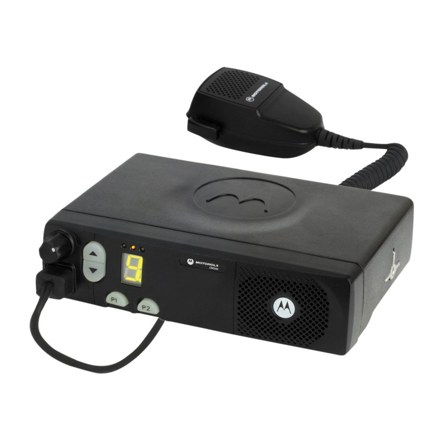
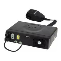
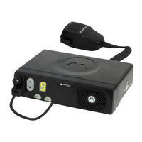
Motorola CM340 Manuals
Manuals and User Guides for Motorola CM340. We have
7
Motorola CM340 manuals available for free PDF download: Detailed Service Manual, Service Information, Basic Service Manual, User Manual
Motorola CM340 Detailed Service Manual (467 pages)
Brand:
Motorola
| Category:
Radio
| Size: 11 MB
Table of Contents
Computer Software Copyrights
6
Your Motorola Two-Way Radio Complies with the Following RF Energy Exposure Standards and Guidelines
8
Mobile Antenna Installation Guidelines
9
Approved Accessories
9
Additional Information
9
Electromagnetic Interference/Compatibility
10
Driver Safety
10
Vehicles with an Air Bag
11
Potentially Explosive Atmospheres
11
Blasting Caps and Areas
11
Table of Contents
13
Chapter 1 INTRODUCTION
15
Scope of Manual
15
Warranty and Service Support
15
Warranty Period and Return Instructions
15
After Warranty Period
15
European Radio Support Centre (ERSC)
16
Piece Parts
16
EMEA Test Equipment Support
16
Technical Support
17
Related Documents
17
Radio Model Information
18
Chapter 2 MAINTENANCE
19
Introduction
19
Preventive Maintenance
19
Inspection
19
Cleaning
19
Safe Handling of CMOS and LDMOS
20
General Repair Procedures and Techniques
20
Notes for All Schematics and Circuit Boards
23
Chapter 3 SERVICE AIDS
27
Recommended Test Tools
27
Test Equipment
29
Computer Software Copyrights
32
Cm140/Cm340Models
35
Cm160/Cm360Models
35
Chapter 2 THEORY of OPERATION
37
Introduction
37
Controlhead Model for CM140 and CM340
37
Power Supplies
37
SPI Interface
37
Keypad Keys
38
Status Leds and Backlight Circuit
38
Microphone Connector Signals
38
Speaker
39
Electrostatic Transient Protection
39
Controlhead Model for CM160 and CM360
40
Power Supplies
40
SPI Interface
40
Keypad Keys
41
LCD Driver
41
Status Leds and Backlight Circuit
41
Microphone Connector Signals
41
Speaker
42
Electrostatic Transient Protection
42
Troubleshooting Charts
43
Controlhead Failure
43
Button/Tones Select Error
44
Button/Tones Select Error
47
Controlhead Pcb / Schematics / Parts Lists
49
Allocation of Schematics and Circuit Boards
49
Computer Software Copyrights
58
Chapter 1 MODEL CHART and TECHNICAL SPECIFICATIONS
61
CM340/CM360 Model Chart
61
Technical Specifications
62
Chapter 2 THEORY of OPERATION
65
Introduction
65
Midband (66-88Mhz) Receiver
65
Receiver Front-End
65
Receiver Back-End
66
Midband (66-88Mhz) Transmitter Power Amplifier
66
First Power Controller Stage
66
Power Controlled Driver Stage
67
Final Stage
67
Bi-Directional Coupler
67
Antenna Switch
67
Harmonic Filter
68
Power Control
68
Midband (66-88Mhz) Frequency Synthesis
68
Reference Oscillator
68
Fractional-N Synthesizer
69
Voltage Controlled Oscillator (VCO)
70
Synthesizer Operation
71
Controller Theory of Operation
72
Radio Power Distribution
72
Protection Devices
74
Automatic On/Off
74
Microprocessor Clock Synthesiser
75
Serial Peripheral Interface (SPI)
76
SBEP Serial Interface
76
General Purpose Input/Output
76
Normal Microprocessor Operation
77
Static Random Access Memory
78
Control Board Audio and Signalling Circuits
78
Audio Signalling Filter IC and Compander (ASFIC CMP)
78
Transmit Audio Circuits
79
Microphone Input Path
79
PTT Sensing and TX Audio Processing
80
Transmit Signalling Circuits
81
Sub-Audio Data (PL/DPL)
81
High Speed Data
82
Dual Tone Multiple Frequency (DTMF) Data
82
Receive Audio Circuits
83
Squelch Detect
83
Audio Processing and Digital Volume Control
84
Audio Amplification Speaker (+) Speaker
84
Handset Audio
85
Filtered Audio and Flat Audio
85
Receive Signalling Circuits
85
Sub-Audio Data (PL/DPL) and High Speed Data Decoder
85
Alert Tone Circuits
86
Chapter 3 TROUBLESHOOTING CHARTS
87
Troubleshooting Flow Chart for Out-Of-Lock Receiver (Sheet 1 of 2)
88
Troubleshooting Flow Chart for Out-Of-Lock Receiver (Sheet 2 of 2)
89
Troubleshooting Flow Chart for 25W Transmitter (Sheet 1 of 4)
90
Troubleshooting Flow Chart for 25W Transmitter (Sheet 2 of 4)
91
Troubleshooting Flow Chart for 25W Transmitter (Sheet 3 of 4)
91
Troubleshooting Flow Chart for 25W Transmitter
92
Troubleshooting Flow Chart for Synthesizer (Reference Oscillator)
94
Troubleshooting Flow Chart for VCO
95
Troubleshooting Flow Chart for Receiver (Sheet 1 of 2)
96
Troubleshooting Flow Chart for Receiver (Sheet 2 of 2)
97
Troubleshooting Flow Chart for DC Supply (Sheet 1 of 2)
98
Troubleshooting Flow Chart for DC Supply (Sheet 2 of 2)
98
Troubleshooting Flow Chart for DC Supply (2 of 2)
99
Allocation of Schematics and Circuit Boards
101
Midband and Controller Circuits
101
Midband 1-25W PCB 8489012U01 (Rev. C) / Schematics
103
Computer Software Copyrights
122
Chapter 1 MODEL CHART and TECHNICAL SPECIFICATIONS
125
Technical Specifications
126
Chapter 2 THEORY of OPERATION
129
Introduction
129
VHF (136-162Mhz) Receiver
129
Receiver Front-End
129
Receiver Back End
130
VHF Transmitter Power Amplifier (136-162 Mhz)
130
First Power Controller Stage
130
Power Controlled Driver Stage
131
Final Stage
131
Bi-Directional Coupler
131
Antenna Switch
131
Harmonic Filter
132
Power Control
132
VHF (136-162Mhz) Frequency Synthesis
132
Reference Oscillator
132
Fractional-N Synthesizer
133
Voltage Controlled Oscillator (VCO)
134
Synthesizer Operation
135
Controller Theory of Operation
136
Radio Power Distribution
136
Protection Devices
138
Automatic On/Off
138
Microprocessor Clock Synthesiser
139
Serial Peripheral Interface (SPI)
140
SBEP Serial Interface
140
General Purpose Input/Output
140
Normal Microprocessor Operation
141
Static Random Access Memory (SRAM)
142
Control Board Audio and Signalling Circuits
142
Audio Signalling Filter IC and Compander (ASFIC CMP)
142
Transmit Audio Circuits
143
Microphone Input Path
143
PTT Sensing and TX Audio Processing
144
Transmit Signalling Circuits
145
Sub-Audio Data (PL/DPL)
145
High Speed Data
146
Dual Tone Multiple Frequency (DTMF) Data
146
Receive Audio Circuits
147
Squelch Detect
147
Audio Processing and Digital Volume Control
148
Audio Amplification Speaker (+) Speaker
148
Handset Audio
149
Filtered Audio and Flat Audio
149
Receive Signalling Circuits
149
Sub-Audio Data (PL/DPL) and High Speed Data Decoder
149
Alert Tone Circuits
150
Chapter 3 TROUBLESHOOTING CHARTS
151
Troubleshooting Flow Chart for Receiver RF (Sheet 1 of 2)
152
Troubleshooting Flow Chart for Receiver (Sheet 2 of 2)
153
Troubleshooting Flow Chart for 25W Transmitter (Sheet 1 of 3)
154
Troubleshooting Flow Chart for 25W Transmitter (Sheet 2 of 3)
155
Troubleshooting Flow Chart for 25W Transmitter
156
Supply Voltage
156
Troubleshooting Flow Chart for Synthesizer
157
Troubleshooting Flow Chart for VCO
158
Troubleshooting Flow Chart for DC Supply (1 of 2)
159
Troubleshooting Flow Chart for DC Supply (2 of 2)
160
Vhf1 Pcb/ Schematics/ Parts Lists
161
Allocation of Schematics and Circuit Boards
161
VHF1 and Controller Circuits
161
2.1 VHF1 PCB 8486672Z01 Parts List 1-25W
179
Computer Software Copyrights
190
Chapter 1 MODEL CHART and TECHNICAL SPECIFICATIONS
193
CM140/CM340/CM160/CM360 Model Chart
193
Technical Specifications
194
Chapter 2 THEORY of OPERATION
197
Introduction
197
VHF (146-174Mhz) Receiver
197
Receiver Front-End
197
Receiver Back-End
198
First Power Controller Stage
198
Power Controlled Driver Stage
199
Final Stage
199
Directional Coupler
199
Antenna Switch
199
Harmonic Filter
200
Power Control
200
VHF (146-174Mhz) Frequency Synthesis
200
Reference Oscillator
200
Fractional-N Synthesizer
201
Voltage Controlled Oscillator (VCO)
202
Synthesizer Operation
203
Controller Theory of Operation
204
Radio Power Distribution
204
Protection Devices
206
Automatic On/Off
206
Microprocessor Clock Synthesiser
207
Serial Peripheral Interface (SPI)
208
SBEP Serial Interface
208
General Purpose Input/Output
208
Normal Microprocessor Operation
209
Static Random Access Memory
210
Control Board Audio and Signalling Circuits
210
Audio Signalling Filter IC and Compander (ASFIC CMP)
210
Transmit Audio Circuits
211
Microphone Input Path
211
PTT Sensing and TX Audio Processing
212
Transmit Signalling Circuits
213
Sub-Audio Data (PL/DPL)
213
High Speed Data
214
Dual Tone Multiple Frequency (DTMF) Data
214
Receive Audio Circuits
215
Squelch Detect
215
Audio Processing and Digital Volume Control
216
Audio Amplification Speaker (+) Speaker
216
Handset Audio
217
Filtered Audio and Flat Audio
217
Receive Signalling Circuits
217
Sub-Audio Data (PL/DPL) and High Speed Data Decoder
217
Alert Tone Circuits
218
Chapter 3 TROUBLESHOOTING CHARTS
219
Troubleshooting Flow Chart for Receiver RF (Sheet 1 of 2)
220
Troubleshooting Flow Chart for Receiver (Sheet 2 of 2)
221
Troubleshooting Flow Chart for 25W Transmitter (Sheet 1 of 3)
222
Troubleshooting Flow Chart for 25W Transmitter (Sheet 2 of 3)
223
Troubleshooting Flow Chart for 25W Transmitter (Sheet 3 of 3)
224
Troubleshooting Flow Chart for Synthesizer
225
Troubleshooting Flow Chart for VCO
226
Troubleshooting Flow Chart for DC Supply (1 of 2)
227
Troubleshooting Flow Chart for DC Supply (2 of 2)
228
Allocation of Schematics and Circuit Boards
229
VHF2 and Controller Circuits
229
VHF2 1-25W PCB 8488977U01 (Rev. C) / Schematics
231
Computer Software Copyrights
308
Chapter 1 MODEL CHART and TECHNICAL SPECIFICATIONS
311
Technical Specifications
312
Chapter 2 THEORY of OPERATION
315
Introduction
315
VHF (136-162 Mhz) Receiver
315
Receiver Front-End
315
Receiver Back End
316
VHF Transmitter Power Amplifier (136-162 Mhz)
316
First Power Controller Stage
316
Power Controlled Driver Stage
317
Final Stage
317
Bi-Directional Coupler
317
Antenna Switch
317
Harmonic Filter
318
Power Control
318
VHF (136-162 Mhz) Frequency Synthesis
318
Reference Oscillator
318
Fractional-N Synthesizer
319
Voltage Controlled Oscillator (VCO)
320
Synthesizer Operation
321
Controller Theory of Operation
322
Radio Power Distribution
322
Protection Devices
324
Automatic On/Off
324
Microprocessor Clock Synthesiser
325
Serial Peripheral Interface (SPI)
326
SBEP Serial Interface
326
General Purpose Input/Output
326
Normal Microprocessor Operation
327
Static Random Access Memory (SRAM)
328
Control Board Audio and Signalling Circuits
328
Audio Signalling Filter IC and Compander (ASFIC CMP)
328
Transmit Audio Circuits
329
Microphone Input Path
329
PTT Sensing and TX Audio Processing
330
Transmit Signalling Circuits
331
Sub-Audio Data (PL/DPL)
331
High Speed Data
332
Dual Tone Multiple Frequency (DTMF) Data
332
Receive Audio Circuits
333
Squelch Detect
333
Audio Processing and Digital Volume Control
334
Audio Amplification Speaker (+) Speaker
334
Handset Audio
335
Filtered Audio and Flat Audio
335
Receive Signalling Circuits
335
Sub-Audio Data (PL/DPL) and High Speed Data Decoder
335
Alert Tone Circuits
336
Chapter 3 TROUBLESHOOTING CHARTS
337
Troubleshooting Flow Chart for Receiver RF (Sheet 1 of 2)
338
Troubleshooting Flow Chart for Receiver (Sheet 2 of 2)
339
Troubleshooting Flow Chart for 45W Transmitter (Sheet 1 of 3)
340
Troubleshooting Flow Chart for 45W Transmitter (Sheet 2 of 3)
341
Troubleshooting Flow Chart for 45W Transmitter (Sheet 3 of 3)
342
Troubleshooting Flow Chart for Synthesizer
343
Troubleshooting Flow Chart for VCO
344
Troubleshooting Flow Chart for DC Supply (1 of 2)
345
Troubleshooting Flow Chart for DC Supply (2 of 2)
346
Chapter 4 VHF1 PCB / SCHEMATICS / PARTS LISTS
347
Allocation of Schematics and Circuit Boards
347
VHF1 and Controller Circuits
347
Model Chart and Technical Specifications
379
Chapter 1 MODEL CHART and TECHNICAL SPECIFICATIONS
382
Chapter 2 THEORY of OPERATION
383
Introduction
383
VHF (146-174Mhz) Receiver
383
Receiver Front-End
383
Receiver Back-End
384
First Power Controller Stage
384
Power Controlled Driver Stage
385
Final Stage
385
Directional Coupler
385
Antenna Switch
385
Harmonic Filter
386
Power Control
386
VHF (146-174Mhz) Frequency Synthesis
386
Reference Oscillator
386
Fractional-N Synthesizer
387
Voltage Controlled Oscillator (VCO)
388
Synthesizer Operation
389
Controller Theory of Operation
390
Radio Power Distribution
390
Protection Devices
392
Automatic On/Off
392
Microprocessor Clock Synthesiser
393
Serial Peripheral Interface (SPI)
394
SBEP Serial Interface
394
Normal Microprocessor Operation
395
Static Random Access Memory
396
Control Board Audio and Signalling Circuits
396
Audio Signalling Filter IC and Compander (ASFIC CMP)
396
Transmit Audio Circuits
397
Microphone Input Path
397
PTT Sensing and TX Audio Processing
398
Transmit Signalling Circuits
399
Sub-Audio Data (PL/DPL)
399
High Speed Data
400
Dual Tone Multiple Frequency (DTMF) Data
400
Receive Audio Circuits
401
Squelch Detect
401
Audio Processing and Digital Volume Control
402
Audio Amplification Speaker (+) Speaker
402
Handset Audio
403
Filtered Audio and Flat Audio
403
Sub-Audio Data (PL/DPL) and High Speed Data Decoder
403
Alert Tone Circuits
404
Chapter 3 TROUBLESHOOTING CHARTS
405
Troubleshooting Flow Chart for Receiver RF (Sheet 1 of 2)
406
Troubleshooting Flow Chart for Receiver (Sheet 2 of 2)
407
Troubleshooting Flow Chart for 45W Transmitter (Sheet 1 of 3)
408
Troubleshooting Flow Chart for 45W Transmitter (Sheet 2 of 3)
409
Troubleshooting Flow Chart for 45W Transmitter (Sheet 3 of 3)
410
Troubleshooting Flow Chart for Synthesizer
411
Troubleshooting Flow Chart for VCO
412
Troubleshooting Flow Chart for DC Supply (Sheet 1 of 2)
413
Troubleshooting Flow Chart for DC Supply (Sheet 2 of 2)
413
Allocation of Schematics and Circuit Boards
415
VHF2 and Controller Circuits
415
VHF2 25-45W PCB 8486487Z03-B / Schematics
417
VHF2 25-45W PCB 8486487Z04 / Schematics
443
Motorola CM340 Service Information (90 pages)
Brand:
Motorola
| Category:
Radio
| Size: 2 MB
Table of Contents
Computer Software Copyrights
2
Table of Contents
3
Chapter 1 MODEL CHART and TECHNICAL SPECIFICATIONS
5
CM140/CM340/CM160/CM360 Model Chart
5
Technical Specifications
6
Chapter 2 THEORY of OPERATION
9
Introduction
9
UHF (403-440Mhz) Receiver
9
Receiver Front-End
9
Receiver Back End
10
UHF Transmitter Power Amplifier (403-440 Mhz)
10
First Power Controller Stage
10
Power Controlled Driver Stage
11
Final Stage
11
Directional Coupler
11
Antenna Switch
11
Harmonic Filter
12
Power Control
12
UHF (403-440Mhz) Frequency Synthesis
12
Reference Oscillator
12
Fractional-N Synthesizer
13
Voltage Controlled Oscillator (VCO)
14
Synthesizer Operation
15
Controller Theory of Operation
16
Radio Power Distribution
16
Protection Devices
18
Automatic On/Off
18
Microprocessor Clock Synthesiser
19
Serial Peripheral Interface (SPI)
20
SBEP Serial Interface
20
General Purpose Input/Output
20
Normal Microprocessor Operation
21
Static Random Access Memory (SRAM)
22
Control Board Audio and Signalling Circuits
22
Audio Signalling Filter IC and Compander (ASFIC CMP)
22
Transmit Audio Circuits
23
Microphone Input Path
23
PTT Sensing and TX Audio Processing
24
Transmit Signalling Circuits
25
Sub-Audio Data (PL/DPL)
25
High Speed Data
26
Dual Tone Multiple Frequency (DTMF) Data
26
Receive Audio Circuits
27
Squelch Detect
27
Audio Processing and Digital Volume Control
28
Audio Amplification Speaker (+) Speaker
28
Handset Audio
29
Filtered Audio and Flat Audio
29
Receive Signalling Circuits
29
Sub-Audio Data (PL/DPL) and High Speed Data Decoder
29
Alert Tone Circuits
30
Chapter 3 TROUBLESHOOTING CHARTS
31
Troubleshooting Flow Chart for Receiver RF (Sheet 1 of 2)
32
Troubleshooting Flow Chart for Receiver (Sheet 2 of 2)
33
Troubleshooting Flow Chart for 25W Transmitter (Sheet 1 of 3)
34
Troubleshooting Flow Chart for 25W Transmitter (Sheet 2 of 3)
35
Troubleshooting Flow Chart for 25W Transmitter (Sheet 3 of 3)
36
Troubleshooting Flow Chart for Synthesizer
37
Troubleshooting Flow Chart for VCO
38
Troubleshooting Flow Chart for DC Supply (1 of 2)
39
Troubleshooting Flow Chart for DC Supply (2 of 2)
40
Chapter 4 UHF1 PCB/ SCHEMATICS/ PARTS LISTS
41
Allocation of Schematics and Circuit Boards
41
UHF 1-25W PCB 8486684Z01 (Rev.o) / Schematics
43
UHF 1-25W PCB 8486684Z03 (Rev. B) / Schematics
67
Motorola CM340 Basic Service Manual (74 pages)
Brand:
Motorola
| Category:
Radio
| Size: 3 MB
Table of Contents
Table of Contents
9
Chapter 1 INTRODUCTION
11
Scope of Manual
11
Warranty and Service Support
11
Warranty Period and Return Instructions
11
After Warranty Period
11
European Radio Support Centre (ERSC)
12
Piece Parts
12
Technical Support
13
Radio Model Information
14
Chapter 2 MAINTENANCE
15
Introduction
15
Preventive Maintenance
15
Inspection
15
Cleaning Procedures
15
Safe Handling of CMOS and LDMOS Devices
16
Repair Procedures and Techniques - General
17
Disassembling and Reassembling the Radio - General
17
Radio Disassembly - Detailed
18
Control Head Removal
18
Top Cover Removal
20
Main Shield Removal
21
PA Shield and DC Cable Removal
21
Main PCB Removal
22
Disassembly of Control Head - CM140/CM340
24
Disassembly of Control Head - CM160/CM360
24
Radio Assembly
26
Chassis Assembly
26
Control Heads Assembly
27
Control Head Fitting
27
Option Board Installation
28
Radio Exploded Mechanical Views and Parts Lists
29
Radio Assembly - 25W Models
29
Radio Assembly - 40W Models
30
Control Head - CM140/CM340
31
Control Head - CM160/CM360
32
Service Aids
33
Test Equipment
35
11.0 Programming/Test Cable - RKN4083
36
Adapter Cable - FKN8113
37
Transceiver Performance Testing
39
General
39
Setup
39
RF Test Mode (5-Tone Radios)
40
RF Test Mode (MDC Radios)
43
Radio Tuning and Programming
47
Introduction
47
CPS Programming/Flashing Setup with RIB
47
CPS Programming/Flashing Setup Ribless
48
CPS Programming Setup with RIB (Telco Connector)
48
CPS Programming Setup with RIB (Accessory Connector)
49
CPS Programming Setup with RIB
49
Radio Tuning Setup
50
Initial Test Equipment Control Settings
50
Power up Self-Test
51
Error Codes (5-Tone Radios)
51
Error Codes (MDC Radios)
52
Accessories & Connector Pin Functions
53
Accessories
53
Accessory Connector Pin Functions
56
Microphone Connector Pin Functions
57
Model Chart and Test Specification
59
Model Chart (Midband 66-88 Mhz)
59
Model Chart (VHF1 136-162 Mhz)
60
Model Chart (VHF2 146-174 Mhz)
61
Model Chart (UHF1 403-440 Mhz)
62
Model Chart (UHF2 438-470 Mhz)
63
Model Chart (VHF1 136-162 Mhz - High Power)
64
Model Chart (VHF2 146-174 Mhz - High Power)
65
Model Chart (UHF1 403-440 Mhz - High Power)
66
Model Chart (UHF2 438-470 Mhz - High Power)
67
Specifications
68
Glossary
71
Motorola CM340 User Manual (24 pages)
Commercial Series
Brand:
Motorola
| Category:
Radio
| Size: 0 MB
Table of Contents
Table of Contents
3
Radio Overview
5
Radio Controls
5
Microphone Controls
5
Programmable Buttons
6
LCD Display
8
Scroll Keys
8
Audio Signal Tones
9
LED Indicators
10
Getting Started
11
Turning the Radio On-Off
11
Adjusting the Radio's Volume
11
Radio on Indication
11
Selecting a Radio Channel
12
Memory Channel
13
Sending a Call
13
Receiving a Call
14
Cancelling a Call
14
Ending a Call
14
Radio Calls
15
Selective Calls
15
Making a Selective Call
15
Receiving a Selective Call
15
Emergency Calls
16
Features
17
Public Address Mode
17
Car Radio Mute
18
Utilities
19
Scan
19
Call Forward
20
Talkaround
21
External Alarm
21
Lone Worker
22
Power Level
22
Companding
23
Local/Distance
23
Voice Operated Transmit (VOX)
24
Stun/Unstun
24
Motorola CM340 Service Information (26 pages)
Commercial Series Controlhead
Brand:
Motorola
| Category:
Radio
| Size: 1 MB
Table of Contents
Table of Contents
3
Chapter 1 MODEL OVERVIEW
5
Cm140/Cm340Models
5
Cm160/Cm360Models
5
Chapter 2 THEORY of OPERATION
7
Introduction
7
Controlhead Model for CM140 and CM340
7
Power Supplies
7
SPI Interface
7
Keypad Keys
8
Status Leds and Backlight Circuit
8
Microphone Connector Signals
8
Speaker
9
Electrostatic Transient Protection
9
Controlhead Model for CM160 and CM360
10
Power Supplies
10
SPI Interface
10
Keypad Keys
11
LCD Driver
11
Status Leds and Backlight Circuit
11
Microphone Connector Signals
11
Speaker
12
Electrostatic Transient Protection
12
Chapter 3 TROUBLESHOOTING CHARTS
13
Controlhead Failure
13
Button/Tones Select Error (1 of 2)
14
Button/Tones Select Error
14
Motorola CM340 User Manual (12 pages)
Brand:
Motorola
| Category:
Radio
| Size: 1 MB
Table of Contents
Table of Contents
3
Radio Overview
4
Radio Controls
4
Microphone Controls
4
Audio Signal Tones
5
Programmable Buttons
7
Menu Keys (CM360)
7
Menu Navigation Chart (CM360)
8
LCD Display and Icons (CM360)
9
Getting Started
10
Turning the Radio On-Off
10
Adjusting the Volume
10
Radio on Message (CM360)
10
Radio on Indicator (CM340)
10
Selecting a Radio Channel
11
Sending a Call
11
Making a Selective Call
11
Receiving a Call
12
Answering a Call
12
Cancelling a Call
12
Ending a Call
12
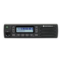
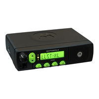
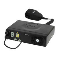
Motorola CM340 User Manual (5 pages)
Brand:
Motorola
| Category:
Two-Way Radio
| Size: 0 MB
Table of Contents
Quality and Reliability
2
Continuous Communication
2
Budget-Conscious
2
Targeted Communication
3
Installation Versatility
3
Intelligent and Customisable
3
A Mobile Radio that Fits Your Business
3
Accessories
4
Technical Specifications
4
Model Numbers
4
Environmental Specifications & Standards
4
Related Products
Motorola CM360
Motorola CM30
Motorola Commercial CM Series
Motorola Commercial CM306
Motorola CP185 Series
Motorola Spectra SmartNet C2
Motorola Spectra SmartNet C4
Motorola Spectra SmartNet C5
Motorola Spectra SmartNet C7
Motorola STORNO CP1000
Motorola Categories
Cell Phone
Two-Way Radio
Baby Monitor
Cordless Telephone
Radio
More Motorola Manuals
Login
Sign In
OR
Sign in with Facebook
Sign in with Google
Upload manual
Upload from disk
Upload from URL