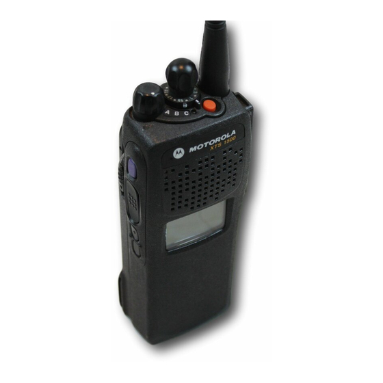
Sign In
Upload
Manuals
Brands
Motorola Manuals
Portable Radio
ASTRO XTS 1500
Motorola ASTRO XTS 1500 Manuals
Manuals and User Guides for Motorola ASTRO XTS 1500. We have
8
Motorola ASTRO XTS 1500 manuals available for free PDF download: Service Manual, Basic Service Manual, User Manual, Manual
Motorola ASTRO XTS 1500 Service Manual (914 pages)
Brand:
Motorola
| Category:
Two-Way Radio
| Size: 51.78 MB
Table of Contents
Foreword
2
Safety Information
2
Manual Revisions
2
Computer Software Copyrights
2
Documentation Copyrights
2
Disclaimer
2
Trademarks
2
Document History
3
Table of Contents
5
Chapter 1 Introduction
27
General
27
Notations Used in this Manual
27
Chapter 2.1 VHF Overall Characteristics
29
Introduction
29
Analog Mode of Operation-Receiving
29
Analog Mode of Operation-Transmitting
30
ASTRO Mode (Digital Mode) of Operation
30
Main Board Overview
30
Vocoder Circuitry Overview
31
Chapter 2.2 UHF1 Overall Characteristics
33
Introduction
33
Analog Mode of Operation-Receiving
33
Analog Mode of Operation-Transmitting
34
ASTRO Mode (Digital Mode) of Operation
34
Main RF Board Overview
34
Vocoder Circuitry Overview
35
Chapter 2.3 UHF2 Overall Characteristics
37
Introduction
37
Analog Mode of Operation-Receiving
37
Analog Mode of Operation-Transmitting
38
ASTRO Mode (Digital Mode) of Operation
38
Main RF Board Overview
38
Vocoder Circuitry Overview
39
Chapter 2.4 700/800 Mhz Overall Characteristics
41
Introduction
41
Analog Mode of Operation-Receiving
41
Analog Mode of Operation-Transmitting
42
ASTRO Mode (Digital Mode) of Operation
42
Main Board Overview
42
Vocoder Circuitry Overview
43
Chapter 2.5 900Mhz Overall Characteristics
45
Introduction
45
Analog Mode of Operation-Receiving
45
Analog Mode of Operation-Transmitting
46
ASTRO Mode (Digital Mode) of Operation
46
Main Board Overview
46
Vocoder Circuitry Overview
47
Chapter 3.1 VHF Radio Power
49
Introduction
49
Radio Power up or down
49
General
49
B+ Routing for VHF Band Main Board
50
Figure 3.1-1. B+ Routing for VHF Main Board
50
B+ and +5V Routing for VOCON
51
Table 3.1-1. Power Supply Configuration for VOCON Section
52
Chapter 3.2 UHF1 Radio Power
53
Introduction
53
Radio Power up or down
53
General
53
B+ Main Board Routing
54
Figure 3.2-1. B+ Routing for Main Board
54
B+ and +5V Routing for VOCON
55
Table 3.2-1. Power Supply Configuration for VOCON Section
56
Chapter 3.3 UHF2 Radio Power
57
Introduction
57
Radio Power up or down
57
General
57
B+ Routing for UHF2 Band Main Board
58
Figure 3.3-1. B+ Routing for Main Board
58
B+ and +5V Routing for VOCON
59
Table 3.3-1. Power Supply Configuration for VOCON Section
60
Chapter 3.4 700/800 Mhz Radio Power
61
Introduction
61
Radio Power up or down
61
General
61
B+ Routing for 700/800 Mhz Band Main Board
62
Figure 3.4-1. B+ Routing for 700/800 Mhz Main Board
62
B+ and +5V Routing for VOCON
63
Table 3.4-1. Power Supply Configuration for VOCON Section
64
Chapter 3.5 900 Mhz Radio Power
65
Introduction
65
Radio Power up or down
65
General
65
B+ Routing for 900 Mhz Band Main Board
66
Figure 3.5-1. B+ Routing for 900Mhz Main Board
66
B+ and +5V Routing for VOCON
67
Figure 3.5-2. XTS 2500/XTS 2500I DC Distribution (for All Other Kits)
67
Table 3.5-1. Power Supply Configuration for VOCON Section
68
Chapter 4.1 VHF Detailed Theories of Operation
69
Introduction
69
Frequency Synthesis
69
Antenna Switch
70
Receiver
70
Front End
71
Back End
71
Transmitter
72
VOCON Functional Blocks
73
Controller and Memory Section
73
Patriot IC (U800)
73
Flash Memory (U803)
76
Sram (U804)
76
Figure 4.1-1. Controller Memory Interface
77
Audio and Power Section
78
Mako IC (U701)
78
Audio Power Amplifier
79
Audio Pre-Amplifier
79
Regulator
79
Interface Support Section
80
Mako IC U701
80
ESD Protection Circuitry
81
Universal Connector (Side Connector) Interface Circuitry
81
Figure 4.1-2. Universal (Side) Connector
82
Figure 4.1-3. VOCON Connector J650
82
Table 4.1-1. Option Select Functions
82
The Option Board
83
Encryption Module
84
Table 4.1-2. Encryption Module Software Kits and Algorithms
84
System Clocks
85
Transmit Audio Path
85
Figure 4.1-4. VOCON Transmit Audio Path
85
Receive Audio Path
86
Figure 4.1-5. VOCON Receive Audio Path
86
Chapter 4.2 UHF1 Detailed Theories of Operation
87
Introduction
87
Frequency Synthesis
87
Antenna Switch
88
Receiver
89
Front End
89
Back End
90
Transmitter
90
VOCON Functional Blocks
91
Controller and Memory Section
91
Patriot IC (U800)
91
Sram (U804)
94
Figure 4.2-1. Controller Memory Interface
95
Flash Memory (U803)
95
Audio and Power Section
96
Mako IC (U701)
96
Audio Power Amplifier
97
Audio Pre-Amplifier
97
Regulator
97
Interface Support Section
98
Mako IC U701
98
ESD Protection Circuitry
99
Universal Connector (Side Connector) Interface Circuitry
99
Figure 4.2-2. Universal (Side) Connector
100
Figure 4.2-3. VOCON Connector J650
100
Table 4.2-1. Option Select Functions
100
The Option Board
101
Encryption Module
102
Table 4.2-2. Encryption Module Software Kits and Algorithms
102
Figure 4.2-4. VOCON Transmit Audio Path
103
System Clocks
103
Transmit Audio Path
103
Figure 4.2-5. VOCON Receive Audio Path
104
Receive Audio Path
104
Chapter 4.3 UHF2 Detailed Theories of Operation
105
Introduction
105
Frequency Synthesis
105
Antenna Switch
106
Receiver
107
Front End
107
Back End
108
Transmitter
108
VOCON Functional Blocks
109
Controller and Memory Section
109
Patriot IC (U800)
109
Flash Memory (U803)
112
Sram (U804)
112
Figure 4.3-1. Controller Memory Interface
113
Audio and Power Section
114
Mako IC (U701)
114
Audio Power Amplifier
115
Audio Pre-Amplifier
115
Regulator
115
Interface Support Section
116
Mako IC U701
116
ESD Protection Circuitry
117
Universal Connector (Side Connector) Interface Circuitry
117
Figure 4.3-2. Universal (Side) Connector
118
Figure 4.3-3. VOCON Connector J650
118
Table 4.3-1. Option Select Functions
118
The Option Board
119
Encryption Module
120
Table 4.3-2. Encryption Module Software Kits and Algorithms
120
Figure 4.3-4. VOCON Transmit Audio Path
121
System Clocks
121
Transmit Audio Path
121
Figure 4.3-5. VOCON Receive Audio Path
122
Receive Audio Path
122
Chapter 4.4 700/800 Mhz Detailed Theories of Operation
123
Introduction
123
Frequency Synthesis
123
Antenna Switch
124
Receiver
125
Front End
125
Back End
126
Transmitter
126
VOCON Functional Blocks
127
Controller and Memory Section
127
Patriot IC (U800)
127
Flash Memory (U803)
130
Sram (U804)
130
Figure 4.4-1. Controller Memory Interface
131
Audio and Power Section
132
Mako IC (U701)
132
Audio Power Amplifier
133
Audio Pre-Amplifier
133
Regulator
133
Interface Support Section
134
Mako IC U701
134
ESD Protection Circuitry
135
Universal Connector (Side Connector) Interface Circuitry
135
Figure 4.4-2. Universal (Side) Connector
136
Figure 4.4-3. VOCON Connector J650
136
Table 4.4-1. Option Select Functions
136
The Option Board
137
Encryption Module
138
Table 4.4-2. Encryption Module Software Kits and Algorithms
138
System Clocks
139
Transmit Audio Path
139
Figure 4.4-4. VOCON Transmit Audio Path
140
Receive Audio Path
140
Figure 4.4-5. VOCON Receive Audio Path
141
Chapter 4.5 900 Mhz Detailed Theories of Operation
143
Introduction
143
Frequency Synthesis
143
Antenna Switch
144
Receiver
145
Front End
145
Back End
146
Transmitter
146
VOCON Functional Blocks
147
Controller and Memory Section
147
Patriot IC (U800)
147
Flash Memory (U803)
150
Sram (U804)
150
Figure 4.5-1. Controller Memory Interface
151
Audio and Power Section
152
Mako IC (U701)
152
Audio Power Amplifier
153
Audio Pre-Amplifier
153
Interface Support Section
153
Regulator
153
Mako IC U701
154
ESD Protection Circuitry
155
Universal Connector (Side Connector) Interface Circuitry
155
Figure 4.5-2. Universal (Side) Connector
156
Figure 4.5-3. VOCON Connector J650
156
Table 4.5-1. Option Select Functions
156
The Option Board
156
Encryption Module
158
Table 4.5-2. Encryption Module Software Kits and Algorithms
158
Figure 4.5-4. VOCON Transmit Audio Path
159
System Clocks
159
Transmit Audio Path
159
Figure 4.5-5. VOCON Receive Audio Path
160
Receive Audio Path
160
Chapter 5 Troubleshooting Procedures
161
Introduction
161
Handling Precautions
161
Voltage Measurement and Signal Tracing
161
Standard Bias Table
162
Table 5-1. Standard Operating Bias
162
Power-Up Self-Check Errors
163
Table 5-2. Power-Up Self-Check Error Codes
163
Operational Error Codes
164
Power-Up, Self-Check Diagnostics, and Repair (Not for Field Use)
164
Table 5-3. Operational Error Code Displays
164
Table 5-4. Additional Error Code Action Items
164
Chapter 6.1 VHF Troubleshooting Charts
167
Introduction
167
List of Troubleshooting Flowcharts
167
VHF Radio Main Troubleshooting Chart
168
Radio Power-Up Fail Troubleshooting Chart (1 of 3)
169
Radio Power-Up Fail Troubleshooting Chart (2 of 3)
170
Radio Power-Up Fail Troubleshooting Chart (3 of 3)
171
DC Supply Fail Troubleshooting Chart (1 of 3)
172
DC Supply Fail Troubleshooting Chart (2 of 3)
173
Volume Set Error Troubleshooting Chart
176
Top/Side Button Error Troubleshooting Chart
178
No Display Troubleshooting Chart (1 of 3)
179
VOCON Transmit Audio Troubleshooting Chart (1 of 2)
185
VOCON Transmit Audio Troubleshooting Chart (2 of 2)
186
No Transmit Deviation Troubleshooting Chart
187
Secure Hardware Failure
189
Chapter 6.2 UHF1 Troubleshooting Charts
191
Introduction
191
List of Troubleshooting Flowcharts
191
UHF Range 1 Radio Main Troubleshooting Chart
192
Radio Power-Up Fail Troubleshooting Chart (1 of 3)
193
Radio Power-Up Fail Troubleshooting Chart (2 of 3)
194
Radio Power-Up Fail Troubleshooting Chart (3 of 3)
195
DC Supply Fail Troubleshooting Chart (1 of 3)
196
DC Supply Fail Troubleshooting Chart (2 of 3)
197
Volume Set Error Troubleshooting Chart
200
Top/Side Button Error Troubleshooting Chart
202
No Display Troubleshooting Chart (1 of 3)
203
No Display Troubleshooting Chart (2 of 3)
204
No Display Troubleshooting Chart (3 of 3)
205
UHF Range 1 Receive RF Troubleshooting Chart
206
VOCON Transmit Audio Troubleshooting Chart (1 of 2)
209
VOCON Transmit Audio Troubleshooting Chart (2 of 2)
210
No Transmit Deviation Troubleshooting Chart
211
Secure Hardware Failure
213
Chapter 6.3 UHF2 Troubleshooting Charts
215
Introduction
215
List of Troubleshooting Flowcharts
215
UHF Range 2 Radio Main Troubleshooting Chart
216
Radio Power-Up Fail Troubleshooting Chart (1 of 3)
217
Radio Power-Up Fail Troubleshooting Chart (2 of 3)
218
Radio Power-Up Fail Troubleshooting Chart (3 of 3)
219
DC Supply Fail Troubleshooting Chart (1 of 3)
220
DC Supply Fail Troubleshooting Chart (2 of 3)
221
DC Supply Fail Troubleshooting Chart (3 of 3)
222
Volume Set Error Troubleshooting Chart
224
Zone/Channel Select Error Troubleshooting Chart
225
Top/Side Button Error Troubleshooting Chart
226
No Display Troubleshooting Chart (1 of 3)
227
No Display Troubleshooting Chart (2 of 3)
228
VOCON Transmit Audio Troubleshooting Chart (1 of 2)
233
VOCON Transmit Audio Troubleshooting Chart (2 of 2)
234
No Transmit Deviation Troubleshooting Chart
235
Secure Hardware Failure
237
Chapter 6.4 700/800 Mhz Troubleshooting Charts
239
Introduction
239
List of Troubleshooting Flowcharts
239
700/800 Mhz Radio Main Troubleshooting Chart
240
Radio Power-Up Fail Troubleshooting Chart (1 of 3)
241
Radio Power-Up Fail Troubleshooting Chart (2 of 3)
242
Radio Power-Up Fail Troubleshooting Chart (3 of 3)
243
DC Supply Fail Troubleshooting Chart (1 of 3)
244
DC Supply Fail Troubleshooting Chart (2 of 3)
245
DC Supply Fail Troubleshooting Chart (3 of 3)
246
Button Test Troubleshooting Chart
263
Volume Set Error Troubleshooting Chart
263
Top/Side Button Error Troubleshooting Chart
263
VOCON Receive Audio Troubleshooting Chart
263
No Transmit Deviation Troubleshooting Chart
263
Secure Hardware Failure
263
Chapter 6.5 900 Mhz Troubleshooting Charts
263
Introduction
263
List of Troubleshooting Flowcharts
263
900 Mhz Radio Main Troubleshooting Chart
264
Radio Power-Up Fail Troubleshooting Chart (1 of 3)
265
Radio Power-Up Fail Troubleshooting Chart (2 of 3)
266
Radio Power-Up Fail Troubleshooting Chart (3 of 3)
267
DC Supply Fail Troubleshooting Chart (1 of 3)
268
DC Supply Fail Troubleshooting Chart (2 of 3)
269
DC Supply Fail Troubleshooting Chart (3 of 3)
270
Volume Set Error Troubleshooting Chart
272
Top/Side Button Error Troubleshooting Chart
274
No Display Troubleshooting Chart (1 of 3)
275
No Display Troubleshooting Chart (2 of 3)
276
No Display Troubleshooting Chart (3 of 3)
277
900 Mhz Receive RF Troubleshooting Chart
278
VOCON Receive Audio Troubleshooting Chart
279
VOCON Transmit Audio Troubleshooting Chart (1 of 2)
281
VOCON Transmit Audio Troubleshooting Chart (2 of 2)
282
No Transmit Deviation Troubleshooting Chart
283
Secure Hardware Failure
285
Advertisement
Motorola ASTRO XTS 1500 Service Manual (817 pages)
Brand:
Motorola
| Category:
Portable Radio
| Size: 44.21 MB
Table of Contents
Foreword
2
Safety Information
2
Manual Revisions
2
Computer Software Copyrights
2
Documentation Copyrights
2
Disclaimer
2
Trademarks
2
Document History
3
Table of Contents
5
Chapter 1 Introduction
25
General
25
Notations Used in this Manual
25
Chapter 2.1 VHF Overall Characteristics
27
Introduction
27
Analog Mode of Operation-Receiving
27
Analog Mode of Operation-Transmitting
28
ASTRO Mode (Digital Mode) of Operation
28
Main Board Overview
28
Vocoder Circuitry Overview
29
Chapter 2.2 UHF1 Overall Characteristics
31
Introduction
31
Analog Mode of Operation-Receiving
31
Analog Mode of Operation-Transmitting
32
ASTRO Mode (Digital Mode) of Operation
32
Main RF Board Overview
32
Vocoder Circuitry Overview
33
Chapter 2.3 UHF2 Overall Characteristics
35
Introduction
35
Analog Mode of Operation-Receiving
35
Analog Mode of Operation-Transmitting
36
ASTRO Mode (Digital Mode) of Operation
36
Main RF Board Overview
36
Vocoder Circuitry Overview
37
Chapter 2.4 700/800 Mhz Overall Characteristics
39
Introduction
39
Analog Mode of Operation-Receiving
39
Analog Mode of Operation-Transmitting
40
ASTRO Mode (Digital Mode) of Operation
40
Main Board Overview
40
Vocoder Circuitry Overview
41
Chapter 2.5 900Mhz Overall Characteristics
43
Introduction
43
Analog Mode of Operation-Receiving
43
Analog Mode of Operation-Transmitting
44
ASTRO Mode (Digital Mode) of Operation
44
Main Board Overview
44
Vocoder Circuitry Overview
45
Chapter 3.1 VHF Radio Power
47
Introduction
47
Radio Power up or down
47
General
47
B+ Routing for VHF Band Main Board
48
Figure 3.1-1.B+ Routing for VHF Main Board
48
B+ and +5V Routing for VOCON
49
Figure 3.1-2.XTS 2500/XTS 2500I DC Distribution (for All Other Kits)
49
Table 3.1-1. Power Supply Configuration for VOCON Section
50
Chapter 3.2 UHF1 Radio Power
51
Introduction
51
Radio Power up or down
51
General
51
B+ Main Board Routing
52
Figure 3.2-1.B+ Routing for Main Board
52
B+ and +5V Routing for VOCON
53
Figure 3.2-2.XTS 2500/XTS 2500I DC Distribution (for All Other Kits)
53
Table 3.2-1. Power Supply Configuration for VOCON Section
54
Chapter 3.3 UHF2 Radio Power
55
Introduction
55
Radio Power up or down
55
General
55
B+ Routing for UHF2 Band Main Board
56
Figure 3.3-1.B+ Routing for Main Board
56
B+ and +5V Routing for VOCON
57
Figure 3.3-2.XTS 2500/XTS 2500I DC Distribution (for All Other Kits)
57
Table 3.3-1. Power Supply Configuration for VOCON Section
58
Chapter 3.4 700/800 Mhz Radio Power
59
Introduction
59
Radio Power up or down
59
General
59
B+ Routing for 700/800 Mhz Band Main Board
60
Figure 3.4-1.B+ Routing for 700/800 Mhz Main Board
60
B+ and +5V Routing for VOCON
61
Figure 3.4-2.XTS 2500/XTS 2500I DC Distribution (for All Other Kits)
61
Table 3.4-1. Power Supply Configuration for VOCON Section
62
Chapter 3.5 900 Mhz Radio Power
63
Introduction
63
Radio Power up or down
63
General
63
B+ Routing for 900 Mhz Band Main Board
64
Figure 3.5-1.B+ Routing for 900Mhz Main Board
64
B+ and +5V Routing for VOCON
65
Figure 3.5-2.XTS 2500/XTS 2500I DC Distribution (for All Other Kits)
65
Table 3.5-1. Power Supply Configuration for VOCON Section
66
Chapter 4.1 VHF Detailed Theories of Operation
67
Introduction
67
Frequency Synthesis
67
Antenna Switch
68
Receiver
68
Front End
69
Back End
69
Transmitter
70
VOCON Functional Blocks
71
Controller and Memory Section
71
Patriot IC (U800)
71
Flash Memory (U803)
74
Sram (U804)
74
Figure 4.1-1.Controller Memory Interface
75
Audio and Power Section
76
Mako IC (U701)
76
Audio Power Amplifier
77
Audio Pre-Amplifier
77
Regulator
77
Interface Support Section
78
Mako IC U701
78
ESD Protection Circuitry
79
Universal Connector (Side Connector) Interface Circuitry
79
Figure 4.1-2.Universal (Side) Connector
80
Figure 4.1-3.VOCON Connector J650
80
Table 4.1-1. Option Select Functions
80
The Option Board
81
Encryption Module
82
Table 4.1-2. Encryption Module Software Kits and Algorithms
82
System Clocks
83
Transmit Audio Path
83
Figure 4.1-4.VOCON Transmit Audio Path
83
Receive Audio Path
84
Figure 4.1-5.VOCON Receive Audio Path
84
Chapter 4.2 UHF1 Detailed Theories of Operation
85
Introduction
85
Frequency Synthesis
85
Antenna Switch
86
Receiver
87
Front End
87
Back End
88
Transmitter
88
VOCON Functional Blocks
89
Controller and Memory Section
89
Patriot IC (U800)
89
Sram (U804)
92
Figure 4.2-1.Controller Memory Interface
93
Flash Memory (U803)
93
Audio and Power Section
94
Mako IC (U701)
94
Audio Power Amplifier
95
Audio Pre-Amplifier
95
Regulator
95
Interface Support Section
96
Mako IC U701
96
ESD Protection Circuitry
97
Universal Connector (Side Connector) Interface Circuitry
97
Figure 4.2-2.Universal (Side) Connector
98
Figure 4.2-3.VOCON Connector J650
98
Table 4.2-1. Option Select Functions
98
The Option Board
99
Encryption Module
100
Table 4.2-2. Encryption Module Software Kits and Algorithms
100
Figure 4.2-4.VOCON Transmit Audio Path
101
System Clocks
101
Transmit Audio Path
101
Figure 4.2-5.VOCON Receive Audio Path
102
Receive Audio Path
102
Chapter 4.3 UHF2 Detailed Theories of Operation
103
Introduction
103
Frequency Synthesis
103
Antenna Switch
104
Receiver
105
Front End
105
Back End
106
Transmitter
106
VOCON Functional Blocks
107
Controller and Memory Section
107
Patriot IC (U800)
107
Flash Memory (U803)
110
Sram (U804)
110
Figure 4.3-1.Controller Memory Interface
111
Audio and Power Section
112
Mako IC (U701)
112
Audio Power Amplifier
113
Audio Pre-Amplifier
113
Regulator
113
Interface Support Section
114
Mako IC U701
114
ESD Protection Circuitry
115
Universal Connector (Side Connector) Interface Circuitry
115
Figure 4.3-2.Universal (Side) Connector
116
Figure 4.3-3.VOCON Connector J650
116
Table 4.3-1. Option Select Functions
116
The Option Board
117
Encryption Module
118
Table 4.3-2. Encryption Module Software Kits and Algorithms
118
Figure 4.3-4.VOCON Transmit Audio Path
119
System Clocks
119
Transmit Audio Path
119
Figure 4.3-5.VOCON Receive Audio Path
120
Receive Audio Path
120
Chapter 4.4 700/800 Mhz Detailed Theories of Operation
121
Introduction
121
Frequency Synthesis
121
Antenna Switch
122
Receiver
123
Front End
123
Back End
124
Transmitter
124
VOCON Functional Blocks
125
Controller and Memory Section
125
Patriot IC (U800)
125
Flash Memory (U803)
128
Sram (U804)
128
Figure 4.4-1.Controller Memory Interface
129
Audio and Power Section
130
Mako IC (U701)
130
Audio Power Amplifier
131
Audio Pre-Amplifier
131
Regulator
131
Interface Support Section
132
Mako IC U701
132
ESD Protection Circuitry
133
Universal Connector (Side Connector) Interface Circuitry
133
Figure 4.4-2.Universal (Side) Connector
134
Figure 4.4-3.VOCON Connector J650
134
Table 4.4-1. Option Select Functions
134
The Option Board
135
Encryption Module
136
Table 4.4-2. Encryption Module Software Kits and Algorithms
136
System Clocks
137
Transmit Audio Path
137
Figure 4.4-4.VOCON Transmit Audio Path
138
Receive Audio Path
138
Figure 4.4-5.VOCON Receive Audio Path
139
Chapter 4.5 900 Mhz Detailed Theories of Operation
141
Introduction
141
Frequency Synthesis
141
Antenna Switch
142
Receiver
143
Front End
143
Back End
144
Transmitter
144
VOCON Functional Blocks
145
Controller and Memory Section
145
Patriot IC (U800)
145
Flash Memory (U803)
148
Sram (U804)
148
Figure 4.5-1.Controller Memory Interface
149
Audio and Power Section
150
Mako IC (U701)
150
Audio Power Amplifier
151
Audio Pre-Amplifier
151
Interface Support Section
151
Regulator
151
Mako IC U701
152
ESD Protection Circuitry
153
Universal Connector (Side Connector) Interface Circuitry
153
Figure 4.5-2.Universal (Side) Connector
154
Figure 4.5-3.VOCON Connector J650
154
Table 4.5-1. Option Select Functions
154
The Option Board
154
Encryption Module
156
Table 4.5-2. Encryption Module Software Kits and Algorithms
156
Figure 4.5-4.VOCON Transmit Audio Path
157
System Clocks
157
Transmit Audio Path
157
Figure 4.5-5.VOCON Receive Audio Path
158
Receive Audio Path
158
Chapter 5 Troubleshooting Procedures
159
Introduction
159
Handling Precautions
159
Voltage Measurement and Signal Tracing
159
Standard Bias Table
160
Table 5-1. Standard Operating Bias
160
Power-Up Self-Check Errors
161
Table 5-2. Power-Up Self-Check Error Codes
161
Operational Error Codes
162
Power-Up, Self-Check Diagnostics, and Repair (Not for Field Use)
162
Table 5-3. Operational Error Code Displays
162
Table 5-4. Additional Error Code Action Items
162
Motorola ASTRO XTS 1500 Basic Service Manual (88 pages)
700 - 800 MHz Digital Portable Radios
Brand:
Motorola
| Category:
Portable Radio
| Size: 6.46 MB
Table of Contents
Computer Software Copyrights
2
Table of Contents
3
List of Figures
7
Commercial Warranty
11
Limited Warranty
11
Specifications
15
Portable Radio Model Numbering System
15
Specifications for 700 Mhz/800 Mhz Radios
16
ASTRO Digital XTS 2500 Model Chart
17
ASTRO XTS 1500/MT 1500 Model Chart
17
1 Introduction
19
General
19
Notations Used in this Manual
19
Radio Description
20
Flashport
20
Table 1.ASTRO XTS 2500 Basic Features
20
2 Basic Maintenance
21
Introduction to this Section
21
Preventive Maintenance
21
Inspection
21
Cleaning
21
Cleaning External Plastic Surfaces
21
Handling Precautions
22
3 Basic Theory of Operation
23
General Overview
23
Figure 1. XTS 2500 Overall Block Diagram
23
Analog Mode of Operation
24
Receiving
24
Transmitting
24
Figure 2. Receiver Block Diagram
24
ASTRO Mode of Operation
25
RF Basic Theory of Operation
25
Figure 3. RF Block Diagram (Power and Control Omitted)
25
Table 2.Local Oscillator and First if Frequencies
25
VOCON Basic Theory of Operation
26
4 Recommended Test Equipment and Service Aids
27
Recommended
27
Test Equipment
27
Table 3.Recommended Test Equipment
27
Service Aids
28
Field Programming Equipment
28
Table 4.Service Aids
28
5 Performance Checks
29
Introduction to this Section
29
Setup
29
Figure 4. Radio Alignment Test Setup
29
Display Radio Test Mode
30
Entering Display Radio Test Mode
30
Table 5.Initial Equipment Control Settings
30
Table 6.Front-Panel Access Test-Mode Displays
30
RF Test Mode (Display Radio)
31
Table 7.Test Frequencies
31
Control Top and Keypad Test Mode (Display Radio)
32
Table 8.Test Environments
32
Non-Display Radio Test Mode
33
Entering Non-Display Radio Test Mode
33
RF Test Mode (Non-Display Radio)
33
Control Top and Keypad Test Mode (Non-Display Radio)
34
Table 9.Receiver Performance Checks
35
Table 10.Transmitter Performance Checks
36
6 Radio Alignment Procedures
37
Introduction to this Section
37
General
37
Figure 5. Tuner Menu Layout
37
Figure 6. Typical Softpot Screen
38
Radio Information
39
Reference Oscillator Alignment
39
Figure 7. Radio Information Screen
39
Figure 8. Reference Oscillator Alignment Screen
40
Table 11.Reference Oscillator Alignment
40
Transmit Power Alignment
41
Table 12.Transmit Power Settings
41
Figure 9. Transmit Power Alignment Screen (Typical)
42
Transmit Deviation Balance Alignment
43
Figure 10. Transmit Deviation Balance Alignment Screen
44
Transmit Deviation Limit Alignment
45
Figure 11. Transmit Deviation Limit Alignment Screen
45
Front End Filter Alignment
46
Definition
46
Procedure for 700 Mhz Frequencies
46
Procedure for 800 Mhz Frequencies
46
Procedure for UHF/VHF
46
Bit Error Rate
47
Definition
47
Bit Error Rate Fields
47
Figure 12. Front End Filter Alignment Screen
47
Figure 13. Bit Error Rate Screen
48
Transmitter Test Pattern
49
Definition
49
Transmitter Test Fields
49
Figure 14. Transmitter Test Pattern Screen
49
7 XTS 2500/XTS 1500/MT 1500 Exploded View and Parts List
51
XTS 2500/XTS 1500/MT 1500 Model I Exploded View
51
Table 13.Model I Exploded View Parts List
51
XTS 2500 Model II Exploded View
52
Table 14.Model II Exploded View Parts List
52
XTS 2500 Model III Exploded View
53
Table 15.Model III Exploded View Parts List
53
Advertisement
Motorola ASTRO XTS 1500 User Manual (82 pages)
Brand:
Motorola
| Category:
Portable Radio
| Size: 1.62 MB
Table of Contents
Table of Contents
9
Declaration of Conformity
5
Computer Software Copyrights
6
Product Safety and RF Exposure Compliance
6
Documentation Copyrights
7
Table of Contents
9
General Radio Operation
13
Notations Used in this Manual
13
XTS 1500 Model 1.5 Radio
14
Physical Features of the XTS 1500 Model 1.5 Radio
15
Programmable Features
16
Backlight
17
Light
17
Display
17
Status Symbols
18
Alert Tones
19
Light Emitting Diode (LED) Indicators
19
Standard Accessories
22
Battery
22
Antenna
25
Belt Clip
26
Universal Connector Cover
27
Remove the Connector Cover
27
Attach the Connector Cover
27
Remote Speaker Microphone Adapter
28
Remove the Adapter
28
Attach the Adapter
28
Radio on and off
29
Turn the Radio on
29
Turn the Radio off
29
Zones and Channels
30
Select a Zone
30
Select a Channel
30
Channel Selection
30
Zone Selection
30
Mode Select Button
31
Receive / Transmit
32
Without Using the Volume Set and Monitor Buttons
32
Use the Preprogrammed Volume Set Button
33
Volume Set
33
Use the Preprogrammed Monitor Button
34
Monitor
34
Conventional Mode Operation
35
Common Radio Features
37
Conventional Squelch Options
37
Analog Squelch
37
PL Defeat
37
Time-Out Timer
38
Emergency
39
Send an Emergency Alarm
39
Send an Emergency Call
40
Scan
42
Turn Scan on and off
42
View a Scan List
42
Scan List Empty
42
Scan On/Off
42
Delete a Nuisance Channel
43
Nuisance Delete
43
Conventional Scan Only
44
Dynamic Priority
44
Telephone Calls (Trunking Only)
45
Answer a Phone Call
45
Phone
45
Private Calls (Trunking Only)
46
Answer a Private Call
46
Call Alert Paging
47
Answer a Call Alert Page
47
Call Response
47
Repeater or Direct Operation
48
Select Repeater or Direct Operation
48
Repeater/Direct
48
Special Radio Features
49
Ptt ID
49
Transmit
49
Trunking System Controls
49
Failsoft
49
Out-Of-Range
50
Site Lock
50
Site Lock/Unlock
50
Site View and Change
51
Site Search
51
Helpful Tips
53
Radio Care
53
Cleaning
53
Handling
53
Service
54
Battery
54
Battery Life
54
Charging the Battery
55
Battery Recycling and Disposal
56
Antenna
57
Accessories
58
Antennas
58
Batteries
58
Carry Accessories
59
Belt Clips
59
Body-Worn
59
Chargers
59
Enhanced and Multi-Unit Line Cords
60
Microphones, Remote Speaker
60
Surveillance Accessories
61
Adapters and Adapter Cable
61
Commport ® Integrated Microphone/Receivers
61
Earpieces
62
Headsets and Headset Accessories
63
Radio Interface Modules for Ear Microphones
63
Switches
63
Appendix: Maritime Radio Use in the VHF Frequency Range
65
Special Channel Assignments
65
Emergency Channel
65
Non-Commercial Call Channel
66
Operating Frequency Requirements
66
Glossary
69
Commercial Warranty
73
Limited Warranty
73
Index
78
Motorola ASTRO XTS 1500 User Manual (82 pages)
Brand:
Motorola
| Category:
Portable Radio
| Size: 9.12 MB
Table of Contents
Product Safety and RF Exposure Compliance
6
Computer Software Copyrights
6
Documentation Copyrights
7
Table of Contents
9
General Radio Operation
13
Notations Used in this Manual
13
XTS 1500 Model 1.5 Radio
14
Physical Features of the XTS 1500 Model 1.5 Radio
15
Programmable Features
16
Display
17
Backlight
17
Status Symbols
18
Light Emitting Diode (LED) Indicators
19
Alert Tones
19
Standard Accessories
22
Battery
22
Antenna
25
Belt Clip
26
Universal Connector Cover
27
Remove the Connector Cover
27
Attach the Connector Cover
27
Remote Speaker Microphone Adapter
28
Remove the Adapter
28
Attach the Adapter
28
Radio on and off
29
Turn the Radio on
29
Turn the Radio off
29
Zones and Channels
30
Select a Zone
30
Select a Channel
30
Mode Select Button
31
Receive / Transmit
32
Without Using the Volume Set and Monitor Buttons
32
Use the Preprogrammed Volume Set Button
33
Use the Preprogrammed Monitor Button
34
Conventional Mode Operation
35
Common Radio Features
37
Conventional Squelch Options
37
Analog Squelch
37
Defeat
37
Time-Out Timer
38
Emergency
39
Send an Emergency Alarm
39
Send an Emergency Call
40
Scan
42
Turn Scan on and off
42
View a Scan List
42
Scan List Empty
42
Delete a Nuisance Channel
43
Conventional Scan Only
44
Telephone Calls (Trunking Only)
45
Answer a Phone Call
45
Private Calls (Trunking Only)
46
Answer a Private Call
46
Call Alert Paging
47
Answer a Call Alert Page
47
Repeater or Direct Operation
48
Select Repeater or Direct Operation
48
Motorola ASTRO XTS 1500 User Manual (66 pages)
Digital Portable Radio Model I
Brand:
Motorola
| Category:
Portable Radio
| Size: 1.45 MB
Table of Contents
Computer Software Copyrights
2
Documentation Copyrights
2
Disclaimer
2
Special Radio Features
5
Trunking System Controls
5
Failsoft
5
Out-Of-Range
5
Site Lock
6
Site Change
6
Table of Contents
7
General Radio Operation
11
Notations Used in this Manual
11
XTS 1500 Model I Radio
12
Physical Features of the XTS 1500 Model I Radio
13
Programmable Features
14
LED Indicators
15
Alert Tones
15
Standard Accessories
18
Battery
18
Antenna
20
Belt Clip
21
Universal Connector Cover
22
Remove the Connector Cover
22
Attach the Connector Cover
22
Remote Speaker Microphone Adapter
23
Remove the Adapter
23
Attach the Adapter
23
Radio on and off
24
Turn the Radio on
24
Turn the Radio off
24
Zones and Channels
25
Select a Zone
25
Select a Channel
25
Receive / Transmit
26
Without Using the Volume Set and Monitor Buttons
26
Use the Preprogrammed Volume Set Button
27
Use the Preprogrammed Monitor Button
28
Conventional Mode Operation
29
Common Radio Features
31
Conventional Squelch Options
31
Analog Squelch
31
PL Defeat
31
Time-Out Timer
32
Emergency
33
Send an Emergency Alarm
34
Send an Emergency Call
35
Scan
37
Turn Scan on and off
37
Delete a Nuisance Channel
37
Conventional Scan Only
38
Telephone Calls (Trunking Only)
39
Answer a Phone Call
39
Private Calls (Trunking Only)
40
Answer a Private Call
40
Call Alert Paging
41
Answer a Call Alert Page
41
Repeater or Direct Operation
42
Select Repeater or Direct Operation
42
Mute
42
Motorola ASTRO XTS 1500 Basic Service Manual (98 pages)
Brand:
Motorola
| Category:
Portable Radio
| Size: 14.03 MB
Motorola ASTRO XTS 1500 Manual (2 pages)
WARN 01 thru WARN 12
Brand:
Motorola
| Category:
Portable Radio
| Size: 0.17 MB
Advertisement
Related Products
Motorola ASTRO XTS 1500 I
Motorola ASTRO XTSTM 1500
Motorola Astro XTSTM 5000
Motorola ASTRO XTS 500
Motorola ASTRO XTSTM4250
Motorola ASTRO XTSTM 4000
Motorola ASTRO XTSTM 2250
Motorola ASTRO XTS 3000 R
Motorola Astro XTS 4000
Motorola ASTRO XTSTM 2500 II
Motorola Categories
Cell Phone
Two-Way Radio
Baby Monitor
Cordless Telephone
Radio
More Motorola Manuals
Login
Sign In
OR
Sign in with Facebook
Sign in with Google
Upload manual
Upload from disk
Upload from URL