Sign In
Upload
Manuals
Brands
Motorola Manuals
Accessories
8900 - Blackberry Curve Cell Phone OEM Car Charger
Motorola 8900 - Blackberry Curve Cell Phone OEM Car Charger Manuals
Manuals and User Guides for Motorola 8900 - Blackberry Curve Cell Phone OEM Car Charger. We have
1
Motorola 8900 - Blackberry Curve Cell Phone OEM Car Charger manual available for free PDF download: Developer's Manual
Motorola 8900 - Blackberry Curve Cell Phone OEM Car Charger Developer's Manual (98 pages)
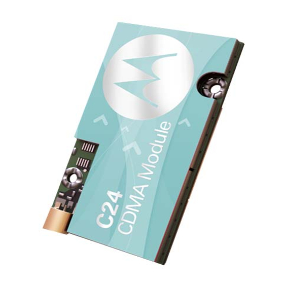
CDMA Module
Brand:
Motorola
| Category:
Accessories
| Size: 1.32 MB
Table of Contents
Technical Information
1
Table of Contents
5
Manual Scope
11
Target Audience
11
Manual Organization
11
Applicable Documents
12
Regulatory Requirements
12
Safety Statement and Requirements
12
Antenna and Transmission Safety Precautions
13
Standards
13
Contact Us
14
Text Conventions
14
Field Service
16
General Safety
16
Caring for the Environment
17
Limitation of Liability
19
Warranty Notification
20
How to Get Warranty Service
20
Claiming
21
Conditions
21
What Is Not Covered by the Warranty
22
Installed Data
22
Out of Warranty Repairs
22
Revision History
23
Chapter 1: Introduction
25
Product Specifications
26
Certifications Approvals
28
Regulatory Approvals
29
CFR 47 Part 15.19 Specifies Label Requirements
29
CFR 47 Part 15.21 Information to User
29
CFR 47 Part 15.105 Information to the User
29
Chapter 2: Hardware Interface Description
31
Architecture Overview
31
C24 Block Diagram
31
Analog Block
32
CDMA Transceiver Block
32
Digital Block
32
Operating Modes
33
C24 Operating Modes
33
Power Supply
34
Power Supply Design
34
Power Supply Signals
34
Recommended Power Supply Filtering
34
Power Consumption
35
C24 Current Ratings
35
Power On/Off Operation
36
Turning the C24 on
36
Turning the C24 on Using ON_N
36
ON_N Power on Timing
36
Turning the C24 on Using IGN
37
Turning the C24 off
37
Turning the C24 off Using ON_N
37
IGN Power on Timing
37
Turning the C24 off Using IGN
38
ON_N Power off Timing
38
IGN Power off Timing
38
Turning the C24 off Using AT+MRST
39
Power Loss Shut down
39
Low Power Mode
40
Activating Low Power Mode
40
ATS24 Operation
40
Serial Interface During Low Power Mode
41
Terminating Low Power Mode
41
CTS Signal During Sleep Mode
41
Temporary Termination of Low Power Mode
42
WKUPI_N Signal Operation
42
Permanent Termination of Low Power Mode
43
Serial Interface Data
43
Real Time Clock
44
Serial Interfaces
45
Primary UART (UART1)
45
Secondary UART (UART2)
45
UART1 Interface Signals
45
USB Interface
46
UART2 Interface Signals
46
USB Interface Signals
46
UIM Interface
47
UIM Connection
47
C24 UIM Interface
47
UIM Design Guidelines
48
UIM Interface Signals
48
Audio Interface
49
Handset Microphone Port
49
Audio Interface Topology
49
Headset Microphone Port
50
Handset Microphone Circuit
50
Handset Microphone Port Specifications
50
Speaker Port
51
Headset Microphone Circuit
51
Headset Microphone Port Specifications
51
Differential Speaker Circuit
52
Single-Ended Speaker Circuit
52
Headset Detection
53
Speaker Port Specifications
53
Alert Loudspeaker Port
54
Differential Loudspeaker Circuit
54
Single-Ended Loudspeaker Circuit
54
Digital Audio Interface
55
Alert Port Specifications
55
Operating Modes
56
Basic Mode
56
Advanced Mode
56
Voiceband Mode PCM Bus Coding Format
56
Basic Mode Audio Paths
56
Audio Programming Interface
57
Advanced Mode Commands
57
Audio Algorithms
58
Audio Programming Interface
58
Speech Processing Features
58
Gain Control
59
Gain Control Features
59
Speaker Port Gains for Speech
59
Audio Design
60
Microphone and Headset Microphone Port Gains
60
Analog Ground
61
A/D Interface
62
General Purpose A/D
62
Power Supply A/D
62
GPAD Specifications
62
Supply A/D Specifications
63
Controls and Indicators Interface
64
Reset
64
VREF Reference Regulator
64
Controls and Indicators
64
Wakeup out
65
VREF Power-Up Timing
65
VREF Specifications
65
Antenna Detection
67
CDMA Network Indicator
67
Transmission Indicator
67
General Purpose I/O
67
GPS Interface
68
GPS Receiver Specifications
68
Antenna Interface
69
Antenna Interface Specifications
69
Chapter 3: Electrical and Environmental Specifications
71
Absolute Maximum Ratings
71
Maximum Ratings
71
Environmental Specifications
72
Application Interface Specifications
72
Environmental Ratings
72
Interface Specifications
73
Chapter 4: Mechanical Specifications
79
Board Dimensions
79
C24 Mechanical Characteristics
79
Interface Connector Specifications
80
C24 Interface Connector
80
C24 Interface Connector Options
80
Mating Connector
81
Mating Connector Dimensions
81
RF Connector Specifications
82
Mating Connector
82
MMCX Connector Dimensions
82
Optional MMCX Cable Assembly
83
C24 Mounting
84
C24 Mounting Area
84
Chapter 5: Service and Testing
85
Service
85
Who to Contact
85
Required Query Information
85
Motorola Workflow
86
Service Centers
87
Testing a Standalone Unit
88
Test Setup
88
Test Setup
89
Test Procedure
90
Acronyms and Abbreviations
91
Index
95
Advertisement
Advertisement
Related Products
Motorola 89425P
Motorola 89131N - Smartphone-Based GPS Navigation System T815
Motorola 89323N
Motorola 89365N
Motorola 89333N
Motorola 89242N - EQ5 - Bluetooth hands-free Speakerphone
Motorola 89504N
Motorola 89503N
Motorola 89536N
Motorola 89409
Motorola Categories
Cell Phone
Two-Way Radio
Baby Monitor
Cordless Telephone
Radio
More Motorola Manuals
Login
Sign In
OR
Sign in with Facebook
Sign in with Google
Upload manual
Upload from disk
Upload from URL