Sign In
Upload
Manuals
Brands
MKS Manuals
Industrial Equipment
670B
User Manuals: MKS 670B Signal Conditioner
Manuals and User Guides for MKS 670B Signal Conditioner. We have
1
MKS 670B Signal Conditioner manual available for free PDF download: Instruction Manual
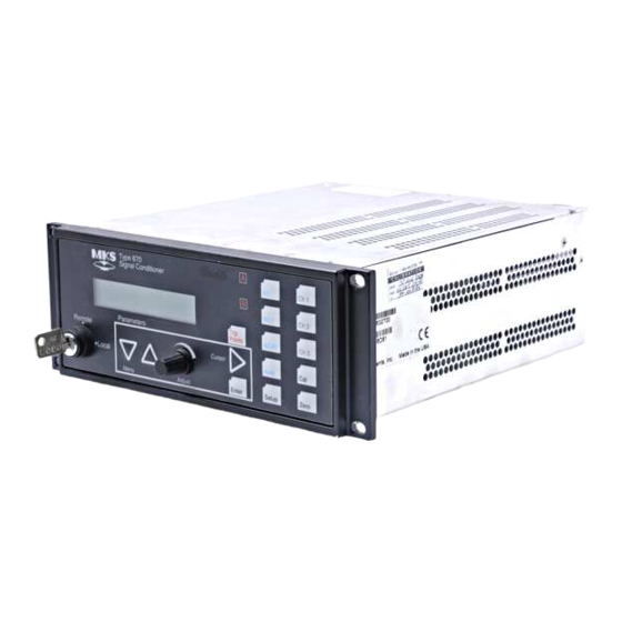
MKS 670B Instruction Manual (168 pages)
High Accuracy Signal Conditioner
Brand:
MKS
| Category:
Industrial Equipment
| Size: 3 MB
Table of Contents
Table of Contents
6
Safety Information
16
Symbols Used in this Instruction Manual
16
Symbols Found on the Unit
17
Table 1: Definition of Symbols Found on the Unit
17
Safety Procedures and Precautions
18
Sicherheitshinweise
20
In dieser Betriebsanleitung Vorkommende Symbole
20
Am Gerät Angebrachte Symbole
21
Tabelle 2: Definitionen der am Gerät Angebrachten Symbole
21
Sicherheitsvorschriften und Vorsichtsmaßnahmen
22
Informations Relatives À la Sécurité
24
Symboles Utilisés Dans Ce Manuel D'utilisation
24
Symboles Apparaissant Sur L'appareil
25
Mesures de Sécurité Et Mises en Garde
26
Información sobre Seguridad
28
Símbolos Usados en el Manual de Instrucciones
28
Símbolos que Aparecen en la Unidad
29
Procedimientos y Precauciones de Seguridad
30
Chapter One: General Information
32
Introduction
32
How this Manual Is Organized
33
Manual Conventions
34
Customer Support
35
Chapter Two: Installation
36
How to Unpack the Type 670 Unit
36
Unpacking Checklist
36
Interface Cables
38
System Interface Cables
38
Table 5: System Interface Cables
38
Remote Communications Interface Cables
39
Table 6: Interface Cables for Remote Communications
39
Generic Shielded Cable Description
40
Example 1: Preferred Method to Connect Cable
41
Example 2: Alternate Method to Connect Cable
41
Figure 1: Preferred Method
41
Figure 2: Alternate Method to Use When Cable Clamp Is Not Available
41
Product Location and Requirements
42
Operating Environmental Requirements
42
Safety Conditions
42
Electrical Requirements
42
Dimensions
43
Figure 3: Front View Dimensions
43
Figure 4: Side View Dimensions
43
Figure 5: Top View Dimensions
44
Chapter Three: Hardware Overview
46
Front Panel
46
Key Lock Switch
46
Figure 6: the Front Panel
46
Display Area
47
Trip Point Leds
47
Range Selector Keys
47
Channel Selector Lights
47
Cursor Key
47
Adjust Knob
47
Arrow Keys
47
Rear Panel
48
Figure 7: the Rear Panel with RS-232 Communications
48
Figure 8: the Rear Panel with IEEE-488 Communications
48
Serial Interface or IEEE-488 Connector
49
Table 7: Pinout of the Serial Interface Connector
49
Table 8: Pinout of the IEEE-488 Connector
50
I/O Connector
51
Pressure Output Signal
51
Table 9: Pinout of the I/O Connector
52
Signal Conditioner Board
53
Table 10: Pinout of the Head Connector on the Signal Conditioner Board
53
Table 11: Pinout of the Signal Connector on the Signal Conditioner Board
54
Power Entry Module
55
Labels
56
Serial Number Label
56
Figure 9: Labels on the Rear Panel
56
Figure 10: Serial Number Label
56
Chapter Four: Functional Overview
58
General Information
58
Color Coded Keys
58
Scrolling
58
Table 12: Color Coding of Front Panel Keys
58
How to Change Entries
59
Display Screen
59
How to Change Channels
60
The [SETUP] Key
60
Display Size
60
Response
61
Table 13: Instrument Response Settings
61
Heater
62
Pressure Units
63
Sensor Range
64
Temperature Compensation
65
Averaging
66
Figure 11: Averaging with 5 Data Points
66
Table 14: Optimal Averaging and Response Entries
67
Communication Parameters (Optional)
68
IEEE-488 Communication Parameters (Optional)
68
The [TRIP POINTS] Key
69
Trip Point Settings
69
Table 15: Action of the Trip Points
69
Hysteresis
71
Figure 12: Hysteresis Bands Applied to the Trip Point Values
71
Figure 13: Hysteresis Bands and Trip Point Values
71
Relay State
72
Channel Selection
73
Latching a Trip Point
73
The [CAL] Key
75
Null
75
Full Scale
75
System Check Calibration
76
The [ZERO] Key
77
Zero Enable
77
Zero Calibration
77
The [AUTO] and Range Keys
79
Figure 14: Autoranging on a 10 Volt Full Scale Signal
79
Chapter Five: Operation
82
How to Configure the 670 Instrument
82
Figure 15: Connecting to a Single Pressure Transducer
82
How to Interface to the Type 274 Multiplexer
84
Connecting the Cables
84
Figure 16: Connecting to a Type 274 Multiplexer
84
Configuring the 274 Multiplexer
85
Configuring the 670 Instrument
85
How to Set the Sensor Full Scale Entry
86
How to Calibrate the 670 Instrument
87
Table 16: Relationship between Averaging Entry and Calibration Times
88
Additional Calibration for the Type 274 Multiplexer
89
How to Configure the Trip Points
90
How to Disable a Trip Point
92
How to Clear a Latched Trip Point
92
Table 17: Connections to Clear a Latch on the Trip Points
92
How to Adjust Hysteresis
93
How to Select the Range Setting Remotely
94
Table 18: Pin State for Remote Range Selection
94
How to Use the Remote Zero Feature
95
How to Display the Software Version Number
96
How to Display the Heater Current with the Pressure Reading
96
How to Change the Line Voltage Selection
97
How to Use the SYSCHK Feature
98
Chapter Six: RS-232 Communications Option
100
General Information
100
Communication Parameters
100
Table 19: RS-232 Communication Parameters
100
RS-232 Protocol
101
Message Syntax
101
Commands
101
Requests
102
Responses
102
Table 20: Responses for Rejected Commands
103
RS-232 Messages
104
Global Messages
105
Table 21: RS-232 Global Messages
105
Channel-Specific Messages
107
Table 22: RS-232 Channel-Specific Messages
107
Trip Point Messages
111
Table 23: RS-232 Trip Point Messages
111
Diagnostic Messages
113
Table 24: RS-232 Diagnostic Messages
113
Table 25: I/O Connector Output Bit Assignment
114
Table 26: I/O Connector Input Bit Assignment
116
Chapter Seven: IEEE-488 Communications Option
118
General Information
118
Key Lock Switch
118
IEEE-488 Device Compliance
119
Buffer Length
119
Address
119
Table 27: IEEE-488 Device Compliance
119
Status Information
120
Figure 17: IEEE-488 Registers
120
Standard Event Status Register
121
Table 28: Standard Event Status Register
121
Status Byte Register
122
Table 29: Status Byte Register
122
Generating a Service Request
123
Table 30: Commands for the Enable Registers
123
IEEE-488 Messages
124
Clear Status Command (*CLS)
124
Operation Complete Messages
124
Wait-To-Continue Command (*WAI)
124
Identification Query (*IDN?)
125
Reset Command (*RST)
125
Self-Test Query (*TST?)
125
Table 31: Identification Query Response
125
MKS Device Dependent Messages
126
Command Syntax
126
Global Configuration Messages
127
Table 32: IEEE-488 Global Messages
127
Channel-Specific Messages
130
Table 33: IEEE-488 Channel-Specific Messages
130
Trip Point Messages
136
Table 34: IEEE-488 Trip Point Messages
136
Diagnostic Messages
139
Table 35: IEEE-488 Diagnostic Messages
139
Chapter Eight: Maintenance and Troubleshooting
142
General Information
142
How to Clean the Unit
142
How to Replace the Fuses
143
Table 36: Fuses for the Type 670 Instrument
143
Troubleshooting
145
Troubleshooting Chart
147
Figure 18: Troubleshooting Flow Chart
147
Test A: Localizing Malfunction to the Cable or the Electronics Unit
148
Figure 19: Two Resistors Added to the Transducer Cable
149
Table 37: Transducer Cable Voltage Check
149
Test B: Localizing Malfunctions to the Electronics Unit
151
Table 38: Electronics Unit Voltage Check
151
Appendix A: Product Specifications
152
Performance Specifications
152
Physical Specifications
154
Environmental Specifications
155
Electrical Specifications
155
Appendix B: Model Code Explanation
156
Model Code
156
Appendix C: Initial Settings
158
General Information
158
Table 39: Initial Settings
158
Table 40: Pinout of the Y-Cable 25-Pin Male Connector
161
Table 41: Pinout of the Y-Cable 25-Pin Female Connector
162
Advertisement
Advertisement
Related Products
MKS Baratron 626A
MKS Baratron 628A
MKS 651C
MKS 647B
MKS Baratron 623F13TBD
MKS Baratron 626D12TBE
MKS Baratron 626D01TDE
MKS Baratron 626D11TQE
MKS 653B
MKS 66087
MKS Categories
Controller
Measuring Instruments
Transducer
Control Unit
Industrial Equipment
More MKS Manuals
Login
Sign In
OR
Sign in with Facebook
Sign in with Google
Upload manual
Upload from disk
Upload from URL