Sign In
Upload
Manuals
Brands
Mitsubishi Manuals
Media Converter
GX Configurator-AD
Mitsubishi GX Configurator-AD Manuals
Manuals and User Guides for Mitsubishi GX Configurator-AD. We have
2
Mitsubishi GX Configurator-AD manuals available for free PDF download: User Manual
Mitsubishi GX Configurator-AD User Manual (208 pages)
MELSEC-Q Series, Programmable Logic Controller, Channel Isolated High Resolution Analog-Digital Converter Module With Signal Conditioning Function
Brand:
Mitsubishi
| Category:
Controller
| Size: 3.38 MB
Table of Contents
Safety Precautions
3
Revisions
6
Table of Contents
7
About Manuals
11
Conformation to the EMC Directive and Low Voltage Instruction
12
About the Generic Terms and Abbreviations
13
Product Structure
14
1 Overview
15
Features
15
2 System Configuration
18
Applicable Systems
18
How to Check the Function Version, Serial Number, Product Information and Software Version
20
Cautions for Power Supply from Q61P-A1/A2 to Q64AD-GH
22
3 Specifications
24
Performance Specifications
24
Performance Specifications List
24
I/O Conversion Characteristic
27
Accuracy
32
Function List
33
A/D Conversion Methods
34
Maximum and Minimum Values Hold Function
36
Input Signal Error Detection Function
36
Warning Output Function
37
A/D Conversion Starting Time Setting Function (Q62AD-DGH Only)
41
I/O Signals for the PLC CPU
42
List of I/O Signals
42
Details of I/O Signals
44
Buffer Memory
51
Buffer Memory Assignment
51
A/D Conversion Enable/Disable Setting (Buffer Memory Address 0: Un\G0)
59
CH Average Time/Average Number of Times/Move Average/Time Constant Settings
60
(Buffer Memory Addresses 1 to 4: Un\G1 to Un\G4)
60
CH A/D Conversion Starting Time Setting (Buffer Memory Addresses 5, 6: Un\G5, Un\G6) (Q62AD-DGH Only)
60
Averaging Process Specification (Buffer Memory Address 9: Un\G9)
61
A/D Conversion Completed Flag (Buffer Memory Address 10: Un\G10)
62
CH Digital Output Value (16Bit) (Buffer Memory Addresses 11 to 14: Un\G11 to Un\G14)
62
Write Data Error Codes (Buffer Memory Address 19: Un\G19)
63
Setting Range (Buffer Memory Address 20: Un\G20)
63
Offset/Gain Setting Mode (Buffer Memory Addresses 22, 23: Un\G22, Un\G23)
64
CH Maximum Value/Minimum Value Storage Area (16Bit)
64
Input Signal Error Detection/Warning Output Settings (Buffer Memory Address 47: Un\G47)
65
Warning Output Flag (Buffer Memory Address 48 :Un\G48)
65
Input Signal Error Detection Flag (Buffer Memory Address 49: Un\G49)
66
CH Maximum Value/Minimum Value Storage Area (32Bit)
67
CH Process Alarm Upper/Lower Limit Value
67
CH Rate Alarm Warning Detection Period (Buffer Memory Addresses 118 to 121: Un\G118 to Un\G121)
68
CH Rate Alarm Upper/Lower Limit Value
69
CH Input Signal Error Detection Setting Value (Buffer Memory Addresses 138 to 141: Un\G138 to Un\G141)
70
Mode Switching Setting (Buffer Memory Addresses 158, 159: Un\G158, Un\G159)
71
Pass Data Classification Setting (Buffer Memory Addresses 200: Un\G200) (Q64AD-GH Only)
71
Industrial Shipment Settings and User Range Settings Offset/Gain Value (Buffer Memory Addresses 202 to 233: Un\G202 to Un\G233)
72
4 Setup and Procedures before Operation
73
Handling Precautions
73
Part Identification Nomenclature
75
Wiring
77
Wiring Precautions
77
External Wiring
78
Switch Setting for Intelligent Function Module
80
Offset/Gain Settings
82
Offset/Gain Settings (Q64AD-GH)
82
Offset/Gain Settings (Q62AD-DGH)
86
A/D Conversion Value Storage During Offset/Gain Setting
89
5 UTILITY PACKAGE (GX Configurator-AD)
90
Utility Package Functions
90
Installing and Uninstalling the Utility Package
91
User Precautions
91
Operating Environment
93
Explanation of Utility Package Operation
94
How to Perform Common Utility Package Operations
94
Operation Overview
97
Starting the Intelligent Function Module Utility
99
Initial Setting
102
Automatic Refresh Setting
104
Monitor/Test
106
Monitor/Test Screen
106
Offset/Gain Setting Operation
109
Confirmation of Conversion Characteristic
110
Pass Data (Q64AD-GH)
112
Pass Data (Q62AD-DGH)
114
FB Conversion of Initial Setting/Auto Refresh Setting
115
Usage of FB
116
Outline
116
Paste an FB to a Sequence Program
118
Convert (Compile) a Sequence Program
119
6 Programming
121
Programming Procedure
121
For Use in Normal System Configuration (Q64AD-GH)
122
Programming Example Using the Utility Package
123
Programming Example Without Using the Utility Package
125
For Use in Remote I/O Network (Q64AD-GH)
127
Programming Example Using the Utility Package
132
Programming Example Without Using the Utility Package
132
For Use in Normal System Configuration (Q62AD-DGH)
135
Programming Example Using the Utility Package
136
Programming Example Without Using the Utility Package
138
For Use in Remote I/O Network (Q62AD-DGH)
139
Programming Example Using the Utility Package
140
Programming Example Without Using the Utility Package
140
7 Online Module Change
146
Online Module Change Conditions
147
Online Module Change Operations
148
Online Module Change Procedure
149
When Industrial Shipment Setting Is Used and Initial Setting was Made with GX Configurator-AD
149
When Industrial Shipment Setting Is Used and Initial Setting was Made with Sequence Program
154
When User Range Setting Is Used and Initial Setting was Made with GX Configurator-AD
159
(Other System Is Available)
159
When User Range Setting Is Used and Initial Setting was Made with GX Configurator-AD
164
(Other System Is Unavailable)
164
When User Range Setting Is Used and Initial Setting was Made with Sequence Program
170
(Other System Is Available)
170
(Other System Is Unavailable)
175
Range Reference Table
176
Precautions for Online Module Change
181
8 Troubleshooting
182
Error Code List
182
Troubleshooting
183
When the "RUN" LED Is Flashing or Turned off
184
When the "ERR." LED Is on or Flashing
184
When the "ALM" LED Is on or Flashing
184
When the Digital Output Values Cannot be Read
185
When A/D Conversion Completed Flag Does Not Turn on During Use in Normal Mode
186
Checking the A/D Converter Module Status Using GX Developer System Monitor
186
Appendix
188
Appendix 1 Dedicated Instruction List and Available Devices
188
Appendix 1.1 OFFGAN
189
Appendix 2 Performance Comparison between Q64AD-GH and Q64AD
200
Appendix 3 External Dimensions
201
Advertisement
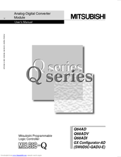
Mitsubishi GX Configurator-AD User Manual (140 pages)
Analog-Digital Converter Module
Brand:
Mitsubishi
| Category:
Media Converter
| Size: 1.24 MB
Table of Contents
Safety Precautions
2
Installation Precautions
3
Revisions
5
Table of Contents
7
Conformation to the EMC Directive and Low Voltage Instruction
10
About the Generic Terms and Abbreviations
10
Product Structure
11
1 Overview
12
Features
12
Functions Added to Function Version B and Later
13
2 System Configuration
14
Applicable Systems
14
How to Check the Function Version and Software Version
16
3 Specifications
18
Performance Specifications
18
Performance Specifications List
18
I/O Conversion Characteristic
19
Accuracy
26
Function List
27
A/D Conversion Methods
27
Maximum and Minimum Values Hold Function
29
I/O Signals for the PLC CPU
29
List of I/O Signals
29
Details of I/O Signals
30
Buffer Memory
34
Buffer Memory Assignment (Q64AD)
34
Buffer Memory Assignment (Q68ADV)
35
Buffer Memory Assignment (Q68ADI)
36
A/D Conversion Enable/Disable Setting (Buffer Memory Address 0: Un\G0)
37
CH Average Time/Average Number of Times
37
Averaging Processing Setting (Buffer Memory Address 9: Un\G9)
38
A/D Conversion Completed Flag (Buffer Memory Address 10: Un\G10)
39
Digital Output Values (Buffer Memory Addresses 11 to 18: Un\G11 to Un\G18)
39
Write Data Error Codes (Buffer Memory Address 19: Un\G19)
40
Setting Ranges (Buffer Memory Addresses 20, 21: Un\G20, Un\G21)
40
Offset/Gain Setting Mode (Buffer Memory Addresses 22, 23: Un\G22, Un\G23)
41
Maximum and Minimum Values Storage Area (Buffer Memory Addresses 30 to 45: Un\G30 to Un\G45)
41
Mode Switching Setting (Buffer Memory Addresses 158, 159: Un\G158, Un\G159)
42
Pass Data Classification Setting (Buffer Memory Addresses 200: Un\G200) (Q64AD Only)
42
Industrial Shipment Settings and User Range Settings Offset/Gain Values (Buffer Memory Addresses 202 to 233: Un\G202 to Un\G233)
43
4 Setup and Procedures before Operation
44
Handling Precautions
44
Part Identification Nomenclature
46
Wiring
48
Wiring Precautions
48
External Wiring
49
Switch Setting for Intelligent Function Module
51
Offset/Gain Settings
53
5 UTILITY PACKAGE (GX Configurator-AD)
57
Utility Package Functions
57
Installing and Uninstalling the Utility Package
58
User Precautions
58
Operating Environment
60
Explanation of Utility Package Operation
61
How to Perform Common Utility Package Operations
61
Operation Overview
64
Starting the Intelligent Function Module Utility
66
Initial Setting
68
Automatic Refresh Settings
69
Monitor/Test
71
Monitor/Test Screen
71
Offset/Gain Setting Operation (Function Version C or Later)
74
Offset/Gain Setting Operation (Function Version B or Earlier)
75
Pass Data (Q64AD)
76
Pass Data (Q68ADV/Q68ADI)
77
6 Programming
79
Programming Example Using the Utility Package
80
Operating the Utility Package
80
Programming Example
81
Programming Example Without Using the Utility Package
82
7 Online Module Change
84
Online Module Change Conditions
84
Online Module Change Operations
85
Online Module Change Procedure
86
When Industrial Shipment Setting Is Used and Initial Setting was Made with GX Configurator-AD
86
When Industrial Shipment Setting Is Used and Initial Setting was Made with Sequence Program
91
When User Range Setting Is Used and Initial Setting was Made with GX Configurator-AD
95
(Other System Is Available)
95
When User Range Setting Is Used and Initial Setting was Made with GX Configurator-AD
99
(Other System Is Unavailable)
99
When User Range Setting Is Used and Initial Setting was Made with Sequence Program
105
(Other System Is Available)
105
When User Range Setting Is Used and Initial Setting was Made with Sequence Program
109
(Other System Is Unavailable)
109
Range Reference Table
109
Precautions for Online Module Change
114
8 Troubleshooting
115
Error Code List
115
Troubleshooting
116
When the "RUN" LED Is Flashing or Turned off
116
When the "ERROR" LED Is on or Flashing
116
When the Digital Output Values Cannot be Read
117
Checking the A/D Converter Module Status Using GX Developer System Monitor
118
Appendix
120
Appendix 1 Function Upgrade for the A/D Converter Module
120
Appendix 1.1 a Comparison of Functions of the A/D Converter Module
120
Appendix 1.2 Combinations of A/D Converter Module Functions and GX Configurator-AD Software Versions
121
Appendix 1.3 Precautions for Replacing the Module of Function Version a with the One of Function Version B or Later
121
Appendix 2 Dedicated Instruction List
122
Appendix 2.1 OFFGAN
123
Appendix 2.2 OGLOAD
125
Appendix 2.3 OGSTOR
129
Appendix 3 External Dimension Diagram
134
Advertisement
Related Products
Mitsubishi GX Configurator-TI
Mitsubishi GX Configurator-DA
Mitsubishi GX Configurator-PT
Mitsubishi Mahindra GX3600
Mitsubishi GX36A
Mitsubishi GX50A
Mitsubishi GOT2000Series
Mitsubishi GB40G
Mitsubishi GB221
Mitsubishi GT2712-STBD
Mitsubishi Categories
Air Conditioner
Controller
Projector
Automobile
Engine
More Mitsubishi Manuals
Login
Sign In
OR
Sign in with Facebook
Sign in with Google
Upload manual
Upload from disk
Upload from URL