Sign In
Upload
Manuals
Brands
Mitsubishi Manuals
Control Unit
E80 Series
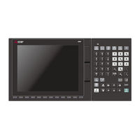
User Manuals: Mitsubishi E80 Series CNC Control Unit
Manuals and User Guides for Mitsubishi E80 Series CNC Control Unit. We have
1
Mitsubishi E80 Series CNC Control Unit manual available for free PDF download: Connection And Set Up Manual
Mitsubishi E80 Series Connection And Set Up Manual (648 pages)
Brand:
Mitsubishi
| Category:
Control Unit
| Size: 35 MB
Table of Contents
Table of Contents
30
System Basic Configuration
38
System Basic Configuration Drawing
39
General Connection Diagram
40
General Connection Diagram [M800S]
41
General Connection Diagram [M80]
43
General Connection Diagram [E80]
47
Connecting a Spindle Drive Unit
47
Connecting a Pulse-Controlled Inverter
49
List of Configuration
52
Control Unit [M800S]
53
Control Unit [M80]
53
Control Unit [E80]
53
Display Unit [M800S]
54
Display Unit [M80]
54
Display Unit [E80]
54
Keyboard Unit [M800S]
55
Keyboard Unit [M80]
55
Keyboard Unit [E80]
55
Operation Panel I/O Unit
56
Remote I/O Unit [M800S/M80]
57
Remote I/O Unit [E80]
58
Function Expansion Unit [M80]
58
Communication Expansion Unit
58
Manual Pulse Generator
59
Synchronous Feed Encoder
59
MITSUBISHI CNC Machine Operation Panel [M800S/M80]
59
MITSUBISHI CNC Machine Operation Panel [E80]
60
Handy Terminal
60
Cable Connector Sets
60
Thermistor Sets
61
Genuine Memory Card
61
Durable Parts
61
Replacements
61
List of Cables
62
System Type
63
General Specifications
64
Environment Conditions [M800S]
65
Installation Environment Conditions
65
24VDC Stabilized Power Supply Selecting Conditions
68
Environment Conditions [M80]
69
Installation Environment Conditions
69
24VDC Stabilized Power Supply Selecting Conditions
72
Environment Conditions [E80]
73
Installation Environment Conditions
73
24VDC Stabilized Power Supply Selecting Conditions
76
Control Unit [M800S]
77
Fcu8-Mu542 / Fcu8-Ma542 / Fcu8-Mu541 / Fcu8-Ma541
77
Control Unit [M80]
89
Fcu8-Mu511 / Fcu8-Mu512 / Fcu8-Mu501 / Fcu8-Mu502
89
Control Unit [E80]
92
Fcu8-Mu513 / Fcu8-Mu514
92
Display Unit [M800S]
96
Type (FCU8-DU141-31)
96
15-Type (FCU8-DU181-31)
98
Precautions
100
Display Unit [M80]
101
Type (FCU8-DU121-12)
101
Type (FCU8-DU141-32)
103
15-Type (FCU8-DU181-32)
105
Precautions
107
Display Unit [E80]
108
Type (FCU8-DU121-13)
108
Precautions
109
Keyboard Unit
110
Keyboard for 8.4-Type Display Unit (FCU8-KB026)
111
Keyboard for 8.4-Type Display Unit (FCU8-KB028)
112
Keyboard for 8.4-Type Display Unit (FCU8-KB029)
113
Keyboard for 10.4-Type Display Unit (FCU8-KB041)
114
Keyboard for 10.4-Type Display Unit (FCU8-KB046)
115
Keyboard for 10.4-Type Display Unit (FCU8-KB047)
116
Keyboard for 10.4-Type Display Unit (FCU8-KB048)
117
Keyboard for 15-Type Display Unit (FCU8-KB083)
118
Keyboard for 8.4-Type Display Unit (FCU8-KB024)
119
Keyboard for 8.4-Type Display Unit (FCU8-KB025)
120
Operation Panel I/O Unit
121
List of Units
121
Fcu8-Dx731 / Fcu8-Dx750 / Fcu8-Dx760 / Fcu8-Dx761 / Fcu8-Dx834
122
Remote I/O Unit
148
List of Units
148
Fcu8-Dx220 / Fcu8-Dx230 / Fcu8-Dx231 / Fcu8-Dx202 / Fcu8-Dx213 / Fcu8-Dx213-1 / Fcu8-Dx654 / Fcu8-Dx654-1 / Fcu8-Dx651/ Fcu8-Dx408 / Fcu8-Dx409
149
Function Expansion Unit
189
Functional Safety Expansion Unit (FCU8-EX133)
189
Communication Expansion Unit
190
CC-Link (FCU8-EX561)
190
Profibus-Dp (Fcu8-Ex563)
193
CC-Link IE Field (FCU8-EX564)
196
Ethernet/Ip (FCU8-EX565)
199
FL-Net (FCU8-EX568)
202
Option Relay Unit (FCU8-EX702)
205
Option Relay Unit (FCU8-EX703)
206
Manual Pulse Generator
207
Manual Pulse Generator (UFO-01-2Z9)
207
Manual Pulse Generator (HD60C)
208
Synchronous Feed Encoder
209
Synchronous Feed Encoder (OSE-1024-3-15-68)
209
MITSUBISHI CNC Machine Operation Panel
211
Main Panel a , B
211
(Fcu8-Kb921 / Fcu8-Kb922 / Fcu8-Kb925 , Fcu8-Kb923 / Fcu8-Kb924 / Fcu8-Kb926)
211
Sub Panel a (FCU8-KB931 / FCU8-KB941)
217
Handy Terminal
222
Thermistor
226
Thermistor(Pt3C-51F-M2)
226
Exclusive SD Cards for MITSUBISHI CNC
227
Specifications and Precautions of USB/SD/LAN Interface
228
USB Interface (Memory I/F Card)
228
SD Interface (Memory I/F Card)
229
LAN Interface (Control Unit)
229
Installation
230
Heat Radiation Countermeasures
231
Noise Countermeasures
234
Connection of Frame Ground (FG)
234
Shield Clamping of Cables
235
Connecting Spark Killers
236
Lightning Surge Protection Countermeasure
237
Unit Installation
238
Display Unit
238
Keyboard Unit
241
Operation Panel I/O Unit
247
Remote I/O Unit
248
Functional Safety Expansion Unit
250
Communication Expansion Unit
251
MITSUBISHI CNC Machine Operation Panel
253
Precautions for Connecting
256
Precautions for Wiring
257
Precautions When Connecting/Disconnecting Cables
257
Precautions for Using Optical Communication Cable
260
Precautions for Connecting 24V Power Supply
261
Turning the Power ON/OFF
262
Connection of Control Unit
264
Control Unit Connection System Drawing
265
Connecting with Power Supply
266
Connecting with Emergency Stop Signal
267
Connecting with Operation Panel I/O Unit
270
Connecting with Remote I/O Unit
271
Connecting with Drive Unit
272
Connecting with Drive Unit MDS-E/EH Series
273
Connection of Optical Communication Cables
273
Drive Unit Arrangement
276
Connecting with Drive Unit MDS-EM/EMH Series
277
Connecting with Drive Unit MDS-EJ/EJH Series
279
Connecting with Pulse-Controlled Inverter [E80]
280
Connecting with RS-232C Device
282
Connecting with Skip Signal (Sensor)
283
Connecting with Manual Pulse Generator
285
Handle Numbers
286
Connecting with Synchronous Feed Encoder
287
Connecting I/O Device Via Communication Expansion Unit
288
Connecting I/O Device Via CC-Link
289
Connecting I/O Device Via PROFIBUS-DP
292
Connecting I/O Device Via CC-Link IE Field
293
Connecting I/O Device Via Ethernet/Ip
294
Connecting I/O Device Via FL-Net
295
Connection of Keyboard Unit
296
Keyboard Unit Connection System Drawing
297
Connecting with Operation Panel I/O Unit
297
Connection of Operation Panel I/O Unit
298
Operation Panel I/O Unit Connection System Drawing
299
Connecting with Power Supply
300
Connecting with Frame Ground
301
Connecting with Control Unit
303
Connecting with Keyboard Unit
303
Connecting with Remote I/O Unit
304
Connecting with Manual Pulse Generator (MPG)
305
Handle Numbers
307
Connecting with Machine Operation Panel
308
Wiring for 24V Common Input
309
Wiring for 0V Common Input
311
Wiring for Source Type Output
313
Example of Wiring CJ42 (FCU8-DX760)
316
Connection with the Scan Input Signal (FCU8-DX834)
317
Connection with the Scan Output Signal (FCU8-DX834)
318
Connecting with Analog Output Signal (FCU8-DX731)
319
Connecting with Analog I/O Signal (FCU8-DX761)
320
Connection of Remote I/O Unit
322
Remote I/O Unit Connection System Drawing
323
Connecting with Power Supply
324
Connecting with Frame Ground
326
Connecting with Control Unit
327
Connecting with Operation Panel I/O Unit
328
Connecting with Machine Control Signal (FCU8-DX220 / FCU8-DX230 / FCU8-DX231 / FCU8-DX651)
329
Connecting with Machine Control Signal (FCU8-DX213 / FCU8-DX213-1 / FCU8-DX654 / FCU8-DX654-1)
334
Connecting with Safety Machine Control Signal (FCU8-DX651)
342
Connecting with Analog I/O Signal (FCU8-DX202)
344
Connecting with Thermistor (FCU8-DX408)
346
Connecting with Multi-Analog Input Signal (FCU8-DX409)
349
Connection of Manual Pulse Generator
358
Manual Pulse Generator Connection System Drawing
359
Connecting with Control Unit
360
Connecting with Operation Panel I/O Unit
360
Connection of Synchronous Feed Encoder
362
Synchronous Feed Encoder Connection System Drawing
363
Connecting with Control Unit
363
Connection of MITSUBISHI CNC Machine Operation Panel
364
Machine Operation Panel Connection System Drawing
365
Connecting with Power Supply
366
Connecting with Frame Ground
367
Connecting with Operation Panel I/O Unit
367
Connecting Emergency Stop Switch
368
Connecting with Sub Panel
368
Software Interface
371
Connection of Handy Terminal
376
Handy Terminal Connection System Drawing
377
Connecting with Control Unit
377
Cable
378
Symbols for Writing Cable Drawings
379
Cable Relating to NC
380
FCUA-R050/R054 Cable
380
G071 Cable
381
G123 Cable
381
G430 Cable
382
G460 Cable
383
J010 Cable
384
J012 Cable
384
J020/J021/J022 Cable
385
J023/J024/J025 Cable
386
J026/J027 Cable
387
J030/J031 Cable
388
J070/J071 Cable
389
J100 Cable
390
J120 Cable
391
J121 Cable
391
J210 Cable
392
J221 Cable
393
J224 Cable
394
J225 Cable
395
J303 Cable
395
J350 Cable
396
J351 Cable
396
J460 Cable
397
J461 Cable
397
R2-TM Terminator Connector
398
Cable Relating to Drive Unit
399
Cable Wire and Assembly
399
CNP2E-1 Cable
400
CNP3EZ-2P/CNP3EZ-3P Cable
401
CNV2E-8P/CNV2E-9P Cable
402
CNV2E-D Cable
403
CNV2E-HP Cable
403
DG30 Cable
404
G380 Cable
404
J395 Cable
405
J396 Cable
406
MR-BKS1CBL-A1-H / MR-BKS1CBL-A2-H Cable
407
MR-BT6V2CBL Cable
407
MR-D05UDL3M-B Cable
408
MR-PWS1CBL-A1-H / MR-PWS1CBL-A2-H Cable
408
SH21 Cable
409
List of Cable Connector Sets
410
Setup Outline
412
Hardware Configuration
413
Flow of Initial Setup
415
Setting the Hardware
418
Setting Drive Unit MDS-E/EH Series
419
Setting the Rotary Switch
419
Setting DIP Switch
420
Setting Drive Unit MDS-EM/EMH Series
421
Setting the Rotary Switch
421
Setting Drive Unit MDS-EJ/EJH Series
422
Setting the Rotary Switch
422
Setting the DIP Switch
423
Setting up Without Connecting to the Motor/Drive Units at the Startup of Drive Unit
424
Connecting the Batteries
425
Control Unit Battery
425
Servo Drive Unit Battery
427
Connecting and Setting the Remote I/O Unit
430
Outline of the Remote I/O Unit
430
Connection and Station No. Setting on Remote I/O Unit
432
Station No. Setting When Using Multiple Remote I/O Units
435
PLC Device Assignment of Digital Signal (DI/DO)
439
Fixed Device Assignment
440
Arbitrary Device Assignment
441
Thermistor Input Interface
445
Initializing the NC Internal Data (SRAM)
446
Setting up with M80/M800S SETUP INSTALLER
448
Activate M80/M800S SETUP INSTALLER
450
Install Custom Screen
452
Install Start-Up Screen
453
Install APLC C Language Module
454
Install User Cycle
455
Setting the Parameters and Date/Time
456
Selecting the NC System Type and Displayed Language
457
Setting the Parameters for the System Specifications
458
Setting the Parameters for the Machine Specifications
459
Setting Date and Time
461
Sequence Program Writing
462
Writing Sequence Program Using the SD Card
463
Setting the Ethernet Communication
463
Confirming the IP Address for CNC
463
Setting the IP Address for PC Side
463
Connecting the Control Unit and a Personal Computer
465
Setting the Communication with GX Developer
466
Setting the Parameters on GX Developer
468
Parameter Setting Screen
468
Setting the Number of Device Points
469
Setting the Number of Common Pointer Points
470
Setting the Program Execution Order
471
Writing a Sequence Program with GX Developer
472
Writing a Sequence Program to ROM with GX Developer
474
Setting the Communication with GX Works2
475
Setting the Parameters on GX Works2
476
Parameter Setting Screen
476
Setting Device Points
477
Setting Common Pointer no
478
Setting Program Executing Order
479
Writing a Sequence Program with GX Works2
480
Writing a Sequence Program to ROM with GX Works2
483
Setting the PLC Parameters
484
Confirming the Basic Operation
486
Checking Inputs/Outputs and Alarms
487
Confirming Manual Operation
488
Using the Manual Pulse Generator
488
Using JOG Feed
488
Servo Simplified Adjustment
489
First Measure against Vibration
489
NC Analyzer2
490
Setting the Position Detection System
492
Adjusting the Absolute Position Detection System
493
Basic Position Alignment Method I
494
Basic Position Alignment Method II
497
Machine End Stopper Method: Automatic Initialization
499
Machine End Stopper Method: Manual Initialization
503
Dog-Type
506
Setting the Grid Interval and the Reference Encoder for Grid Interval
507
Precautions Common for the Initilization Operation
507
Precautions Common for the Dogless-Type Absolute Position Encoder
508
Adjustment of Reference Position Return in Relative Position Detection System
509
Dog-Type Reference Position Return Operation
509
Dog-Type Reference Position Return Adjustment Procedures
510
Setting the Tool Entry Prohibited Range
516
Stroke End (H/W OT)
517
Stored Stroke Limit (S/W OT)
518
Outline
518
Stored Stroke Limit I
521
Stored Stroke Limit II
522
Stored Stroke Limit IB
524
Stored Stroke Limit IC
525
Movable Range During Inclined Axis Control
526
Stored Stroke Limit for Rotation Axis
527
Changing the Area for the Stored Stroke Limit I
527
Precautions
528
Setting the Machine Error Compensation
530
Memory-Type Pitch Error Compensation/Memory-Type Relative Position Error Compensation
531
Outline
531
Setting Compensation Data
533
Setting Method
535
Using a Linear Axis as Basic Axis
535
Using a Rotary Axis as Basic Axis
537
Bidirectional Pitch Error Compensation
538
Outline
538
Setting Method
539
When the Basic Axis Is a Linear Axis
539
When the Basic Axis Is a Rotary Axis
542
Setting the Position Switches
544
Outline
545
Setting and Operation Examples of Dog1 and Dog2
546
Canceling the Position Switch
547
Setting the Backlash Compensation
548
Backlash Compensation
549
Backlash Compensation II
550
Enabling Conditions for Backlash Compensation II
551
Procedure of Setting Backlash Compensation II
551
Setting the Backlash Compensation II Acceleration Rate
551
Setting Compensation Amount of Backlash Compensation II
552
Precautions for Setting Parameters
553
Confirming the Spindle Operation
556
In Manual Operation (with Manual Numerical Command)
557
In MDI Operation
558
Confirming the Rotation Speed
558
Setting the Handy Terminal
560
Inputting the Data from a Personal Computer
561
Inputting the Data from NC
564
Setting the Deceleration Check
566
Function
567
Deceleration Check Method
569
Deceleration Check for Opposite Direction Movement Reversal
571
Parameter
572
Relation with Other Functions
574
Precautions
575
Adjust S-Analog Screen
576
Adjustment Preparations
578
Performing Automatic Adjustments
578
Performing Manual Adjustments
579
Device Open Parameter Screen
582
SRAM Open Parameter Screen
588
Data Backup and Restoration
594
All Backup
596
All Restoration
598
Appx.1: Setting the System Lock
600
Setting the Encryption Key
601
Setting of Expiration Date
602
Display of Time Limit Warning and Alarm Notification
603
Caution
603
Appx.2: Protection Setting
604
Protect Setting Screen
605
Returning the Password to the Non-Input State (Operation Level 0 to 3)
608
Changing the Operation Level to One of 4 to 6
608
Changing the Password
609
Clearing the Password
610
Changing the Protection Level
611
Saving the Protection Level Setting
611
Appx.3: Displaying Original Logo on Standard Screen
612
Appx.4: EMC Installation Guidelines
614
Introduction
615
EMC Directives
615
EMC Measures
616
Panel Structure
616
Measures for Control Panel Body
616
Measures for Door
617
Measures for Power Supply
617
Measures for Wiring in Panel
618
Precautions for Wiring in Panel
618
Shield Treatment of Cables
619
EMC Countermeasure Parts
620
Shield Clamp Fitting
620
Ferrite Core
621
Surge Absorber
622
Selection of Stabilized Power Supply
624
Appx.5: Restrictions for Lithium Batteries
626
Restriction for Packing
627
Target Products
627
Handling by User
628
Reference
628
Products Information Data Sheet (er Battery)
629
Forbiddance of Transporting Lithium Battery by Passenger Aircraft Provided in the Code of Federal Regulation
631
California Code of Regulation "Best Management Practices for Perchlorate Materials
631
Restriction Related to EU Battery Directive
632
Important Notes
632
Information for End-User
632
Appx.6: Precautions for Compliance to Ul/C-UL Standards
634
Advertisement
Advertisement
Related Products
Mitsubishi E85LCD-BK
Mitsubishi EX200U
Mitsubishi DLP EW331U-ST
Mitsubishi E55LCD
Mitsubishi EHPX series
Mitsubishi EW-50A
Mitsubishi EHST20C-VM6EC
Mitsubishi EHPT20X-MHCW
Mitsubishi Eclipse 1994
Mitsubishi Eclipse 1996
Mitsubishi Categories
Air Conditioner
Controller
Projector
Automobile
Engine
More Mitsubishi Manuals
Login
Sign In
OR
Sign in with Facebook
Sign in with Google
Upload manual
Upload from disk
Upload from URL