Sign In
Upload
Manuals
Brands
MIMAKI Manuals
Plotter
CF3-1631
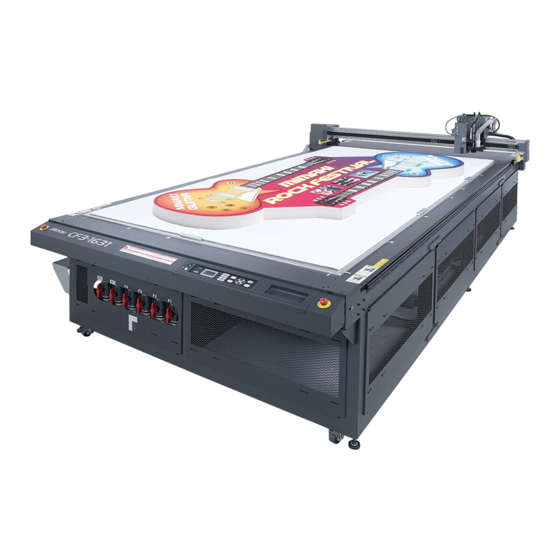
MIMAKI CF3-1631 Manuals
Manuals and User Guides for MIMAKI CF3-1631. We have
2
MIMAKI CF3-1631 manuals available for free PDF download: Operation Manual
MIMAKI CF3-1631 Operation Manual (166 pages)
flat bed cutting plotter
Brand:
MIMAKI
| Category:
Plotter
| Size: 7 MB
Table of Contents
Table of Contents
2
Caution
8
Disclaimer of Warranty
8
FCC Statement (USA) & EN55022 (Europe)
8
Interference to Televisions and Radios
8
Introduction
9
On this Operation Manual
9
Accessories
9
Safety Precautions
10
Symbols
10
How to Read this Manual
13
Warning Labels
14
Chapter 1 Setup
16
Installation
16
Installing the Optional Blower Unit
16
Names and Functions of Parts
17
Main Unit
17
Electrical Box
18
Head
19
Operation Panel
22
Cable Connections
24
Connecting the Power Cable
24
Connecting the Blower Signal Cable
24
Connecting the Interface Cable
24
Turning the Power ON/OFF
25
Turning the Power on
25
Turning the Power off
25
Emergency Stop
26
Applying an Emergency Stop
26
Resetting an Emergency Stop
26
Compressed Air Connection
27
Checking the Compressed Air Pressure
27
Dust Collector Connections
28
Precautions for Dust Collector Connections
28
Connecting the Dust Collector
29
Preparing the Cutting Panel
30
Attach the Felt Mat (Models R1, M)
30
Inserting the Work Guide Plates
30
Blades and Workpieces
31
Workpiece Types that Can be Cut by each Model (Guide)
31
Blade Types that Can be Used in each Model
31
Mounting Tools
32
Mounting the Pen or Swivel Blade
33
Mounting the Tangential Cutter
36
Mounting the Grid Roller
38
Mounting the Reciprocating Cutter
39
Mounting the Milling Tool
41
Local Status / Remote Status
46
Local Status and Displays
46
Remote Status and Displays
47
Matching the PC Specifications
48
Setting the Communication Conditions
48
Enabling PC Commands (CMD SW)
50
Setting the Effective Area Return Values (OH UNIT)
51
Setting the Command Origin
52
Resolution (GDP ) Setting
53
Matching the Plotter Specifications
54
Setting Automatic Head Retraction
55
Setting the Vacuum
56
Enabling / Disabling the Vacuum Automatic off Function
56
Basic Operation Workflow
58
Moving the Head
59
Moving the Head Using the Head Retraction [VIEW] Function
59
Moving the Head Using the Jog Keys
60
Fixing the Workpiece
61
Fixing the Workpiece with Adhesive Tape
61
Fixing the Workpiece by Vacuum Adhesion
62
Selecting Tools
64
Selecting Tools for Model R1 and Model TF2
64
Setting the Z-Axis Origin for Model M
65
Setting the Cutting Conditions
68
Set Items
70
Adjusting the Blade to Match the Workpiece
74
Adjusting the Tangential Cutter
74
Adjusting the Swivel Blade
76
Adjusting the Head Height
77
Making a Test Cut
78
Checking the Tool Status
79
Checking the Status between Tools
82
Setting the Cutting Area
85
Setting the Drawing Origin
87
Cutting (Drawing)
88
Effective Cutting Area
88
Interrupting Processing
89
Restarting Processing
89
Interrupting Processing (Data Clear)
90
Chapter 3 Making the most of the Unit
92
Assigning Pen Numbers
92
Assigning Pen Numbers
93
Cutting the same Data Again (Copy)
94
Setting Multi-Pass Cutting
95
Setting Multi-Pass Cutting (Models R1, TF2)
95
Setting Multi-Pass Cutting (Model M)
97
One Stroke Setting
98
Rotating Coordinate Axes (ROTATE)
99
Setting the Cutter Stroke
100
Setting the Displayed Units
101
Swivel Blade Dummy Cut
102
Setting Axis Alignment
103
Setting the Displayed Language (DISPLAY)
104
Setting NR Head Retraction
105
Setting the Close Time
106
Set Menu
106
Manual Cutting
107
Cleaning the Table
108
Chapter 4 Register Mark Reading Functions
112
Precautions When Creating Data with Register Marks
112
Size of Register Marks
112
Permitted Arrangements of Register Marks and the Design
113
Prohibited Drawing Areas Around Register Marks
114
Guide to Register Mark Separation and Register Mark Size
116
Register Mark Colors
117
Bleeding or Smudging of Register Marks
117
Setting Register Mark Detection
118
Precautions Related to Register Mark Detection
118
Setting Register Mark Detection
119
Detecting Register Marks
120
Using the Light Pointer to Check the Workpiece Tilt
120
Register Mark Detection Procedure
121
Continuous Cutting of Register Marks
122
Clearing the Register Mark Offsets
123
Chapter 5 Daily Maintenance
126
Cutting Panel Surface
126
Covers
126
Daily Maintenance
126
Unit B
127
Cleaning the Blower Filter
128
Cleaning the Dust Collector Brush
129
Maintaining the Dust Collector Hose (When Using M Head)
129
Cleaning the Milling Tool (End Mill)
129
Cleaning with Auxiliary Air
130
Cleaning the Photoelectric Sensors and Register Mark Sensor
130
Replacing the Head with an Optional Head
131
Replacing a Model R1 or TF2 Head with a Model M Head
132
Replacing a Model M Head with a Model R1 or TF2 Head
133
Chapter 6 Troubleshooting
136
Now What Do I Do
136
Adjusting the Tools
137
Adjusting the Cutter
137
Circle Θ Correction
144
Light Pointer Adjustment
147
Troubleshooting
148
Unit Does Not Operate When the Power Is Turned on
148
Unit Does Not Operate after the CAD Data Is Sent
148
An Error Occurs When the Data Is Sent
148
Tool Lifts up the Paper
149
Drawn Lines Are Broken or Smudged
149
No Reciprocating Movement
149
Spindle Motor Does Not Rotate
150
Runout of the End Mill
150
Abnormal Noise or Vibration During Rotation
150
Dust Collector Does Not Work
150
Problems Causing an Error Display
151
Non-Fatal Errors
151
Fatal Errors
153
Errors Displayed on the Spindle Controller
154
Self Test
155
Conducting a Self Test
156
Making an DATA DUMP
158
Making a PARAMETER DUMP
160
Replacing the Fuse
162
Specifications
163
Advertisement
MIMAKI CF3-1631 Operation Manual (166 pages)
FLAT BED CUTTING PLOTTER
Brand:
MIMAKI
| Category:
Plotter
| Size: 9 MB
Table of Contents
Indice
2
Table of Contents
2
Attenzione
8
Limitazione DI Garanzia
8
Dichiarazione FCC (USA) & EN55022 (Europa)
8
Interferenze con Radio E Televisioni
8
Premessa
9
Il Manuale
9
Accessori
9
Per Operazioni Sicure
10
Simboli
10
Come Leggere Questo Manuale
13
Etichette con Avvisi
14
Capitolo 1 Messa in Opera
16
Installazione
16
Installare L'unità Optional DI Ventilazione
16
Nome Delle Parti E Funzioni
17
Unità Principale
17
Morsettiera
18
Testa
19
Cablaggio
24
Collegare Il Cavol Elettrico
24
Collegare Il Cavo del Segnale Dell'unità DI Ventilazione
24
Collegare Il Cavo Dell'interfaccia
24
Accendere/Spegnere la Macchina
25
Accendere la Macchina
25
Spegnere la Macchina
25
Arresto D'emergenza
26
Eseguire un Arresto D'emergenza
26
Rassettare un Arresto D'emergenza
26
Collegamento Ad Aria Compressa
27
Controllo Della Pressione Dell'aria Compressa
27
Collegamento Per Il Raccoglitore DI Polvere
28
Precauzioni Per Il Collegamento del Raccoglitore DI Polvere
28
Collegare Il Raccoglitore DI Polvere
29
Preparare Il Pannello DI Taglio
30
Attaccare Il Tappetino DI Feltro (Modelli R1, M)
30
Inserire Le Piastre Per la Guida del Lavoro
30
Lame E Pezzi da Lavorare
31
Tipi DI Pezzi da Lavorare Che Possono Essere Tagliati da Ciascun Modello (Guida)
31
Tipi DI Lama Che Possono Essere Usati in Ciascun Modello
31
Strumenti da Montare
32
Montare la Penna E la Lama Rotante
33
Montare Il Cutter Tangenziale
36
Montare Il Rullo con la Griglia
38
Montare Il Cutter Alternato
39
Montare lo Strumento Per la Fresatura
41
Funzionamento Locale/Remoto
46
Lo Stato Locale E Il Display
46
Lo Stato Remoto E Il Display
47
Corrispondere alle Specifiche del PC
48
Impostare Le Condizioni DI Comunicazione
48
Attivare I Comandi del PC(CMD SW)
50
Impostare I Valori DI Ritorno Dell'area Effettiva (OH UNIT)
51
Impostare L'origine del Comando
52
Impostazione Della Risoluzione (GDP )
53
Corrispondere alle Specifiche del Plotter
54
Impostare Il Ritiro Automatico Della Testa
55
Impostare Il Vacuum
56
Attivare/Disattivare la Funzione DI Spegnimento Automatico
56
Capitolo 2 Operazioni DI Base
58
Flusso Delle Operazioni DI Base
58
Muovere la Testa
59
Muovere la Testa Usando Le Frecce Direzionali
60
Fissare Il Pezzo da Lavorare
61
Fissare Il Pezzo da Lavorare con Nastro Adesivo
61
Fissare Il Pezzo da Lavorare con L'adesione Vacuum
62
Selezionare Gli Strumenti
64
Impostare Le Condizioni DI Taglio
68
Parametri da Impostare
70
Regolare la Lama Perchè Corrisponda al Lavoro
75
Regolare la Lama Girevole
76
Regolare L'altezza Della Testa
77
Fare un Taglio DI Prova
78
Controllare lo Stato Tra Gli Strumenti
82
Impostare L'area DI Taglio
85
Impostare L'origine del Disegno
87
Tagliare (Disegnare)
88
Area Effettiva DI Taglio
88
Interrompere L'elaborazione
89
Ricominciare L'elaborazione
89
Interrompere L'elaborazione (Data Clear)
90
Capitolo 3 Aumentare Le Potenzialità Della Macchina
92
Assegnazione Dei Numeri DI Penna
92
Taglio con Gli Stessi Dati (Copia)
94
Taglio Multi-Passaggio
95
Come Impostare Il Taglio Multi-Passaggio (Modelli R1, TF2)
95
Come Impostare Il Taglio Multi-Passaggio (Modello M)
97
Impostazione Per Passaggio Unico
98
Rotazione Dell'asse DI Coordinate (ROTATE)
99
Come Impostare la Corsa del Cutter
100
Come Impostare L'unità DI Misura
101
Taglio a Vuoto Della Lama Orientabile
102
Allineamento Degli Assi
103
Lingua Dei Messaggi (DISPLAY)
104
Ritrazione Della Testa
105
Impostazione del Tempo DI Chiusura
106
Taglio Manuale
107
Pulizia Della Tavola
108
Capitolo 4 Funzioni
112
Precauzioni Durante la Creazione DI Dati con Contrassegni DI Registro
112
Dimensione Dei Contrassegni DI Registrazione
112
Configurazione Dei Contrassegni DI Registro E DI Design
113
Aree DI Esclusione Intorno Ai Contrassegni DI Registro
114
Guida Alla Separazione E Alla Dimensione del Contrassegno
116
Colore Dei Contrassegni
117
Rifilare O Sbavare un Contrassegno
117
Come Impostare Il Rilevamento del Contrassegno DI Registro
118
Precauzioni
118
Come Impostare Il Rilevamento del Contrassegno DI Registro
119
Rilevare Il Contrassegno DI Registro
120
Utilizzo del Puntatore Luminoso Per Controllare L'inclinazione del Pezzo
120
Procedura DI Rilevamento del Contrassegno DI Registro
121
Taglio Continuo Dei Contrassegni DI Registro
122
Azzeramento Degli Offset Dei Contrassegni DI Registro
123
Capitolo 5 Manutenzione Quotidiana
125
Manutenzione Quotidiana
125
Coperture
126
Unità B
127
Pulizia del Collare DI Raccolta
129
Manutenzione del Condotto DI Aspirazione Della Polvere
129
Pulizia Della Fresa (End Mill)
129
Pulizia con Aria Ausiliaria
130
Pulizia Dei Sensori Fotoelettrici E del Contrassegno DI Registro
130
Sostituzione Della Testa
131
Tf2
131
Capitolo 6 Eliminazione Dei Guasti
135
Cosa Faccio
136
Regolare Gli Strumenti
137
Regolare Il Cutter
137
Regolare L'angolo Θ
142
Regolare Gli Strumenti
143
Regolare L'angolo Θ
143
Regolazione del Puntatore Luminoso
147
Eliminazione Dei Guasti
148
L'unità Non Funziona Quando È Accesa
148
L'unità Non Funziona Dopo Che I Dati CAD Sono Stati Inviati
148
Si Verifica un Errore Quando I Dati Vengono Inviati
148
Gli Strumenti Sollevano la Carta
149
Le Linee Disegnate Sono Spezzate O Macchiate
149
Nessun Movimento Alternato
149
Runout Della Fresa
150
Il Raccoglitore DI Polvere Non Funziona
150
Il Motore Dell'alberino Non Gira
150
Problemi Che Causano un Messaggio D'errore
151
Problemi Che Causano un Messaggio D'errore
153
Errori Fatali
153
Errori Mostrati Sul Dispositivo DI Controllo
154
Auto-Test
155
Eseguire un Auto-Test
156
Eseguire uno SCARICO DI DATI
158
Eseguire uno SCARICO DI PARAMETRI
160
Sostituire Il Fusibile
162
Specifiche
163
Advertisement
Related Products
MIMAKI CF3-1610
MIMAKI CF-1215
MIMAKI CF-1218
MIMAKI CFL-605RT
MIMAKI CF2-1215
MIMAKI CF2-1218
MIMAKI CF2-0912T
MIMAKI CF2-0912TD
MIMAKI CF2-1215TD
MIMAKI CF2-0912TF
MIMAKI Categories
Printer
Plotter
Printer Accessories
Cutter
Industrial Equipment
More MIMAKI Manuals
Login
Sign In
OR
Sign in with Facebook
Sign in with Google
Upload manual
Upload from disk
Upload from URL