Sign In
Upload
Manuals
Brands
Milnor Manuals
Washer
42030V6Z
Milnor 42030V6Z Manuals
Manuals and User Guides for Milnor 42030V6Z. We have
9
Milnor 42030V6Z manuals available for free PDF download: Operator's Manual, Maintenance Manual, Service Manual, Mechanical Parts And Service, Service, Installation Manual
Milnor 42030V6Z Operator's Manual (346 pages)
Brand:
Milnor
| Category:
Controller
| Size: 7 MB
Table of Contents
Table of Contents
126
Vidange Trop Longue
162
Circuit À 3 Fils Désactivé
162
Trop de Temps Avant Vapeur
162
Refroidissement Trop Long
163
Contrôler la Sonde de Température
163
Niveau en Cours
163
Panne de Communication Série
163
Défaillance du Capteur de Vitesse
164
Inverseur Déclenché
164
Erreur de Défaut Externe
164
Défaut de Pression de Frein
164
Défaut de Pression de Palier
164
Messages Spécifiques Aux Modèles Miltouch-EX
164
Patins de Frein Usés
164
Commande Côté Propreté
164
Contrôler Le Système D'équilibrage/Commutateur D'excursion
165
Messages Spécifiques Aux Modèles Miltouch-EX Chargement/Déchargement Automatique Patins de Frein Usés
165
Chargement Abandonné
165
Déchargement Abandonné
165
4.2. Entrées Et Sorties Pour L'appareil de Contrôle Miltouch
165
Sorties
167
Miltouch 3 (WUMTGUIA 3.X)
167
Miltouch 2 (WUMTGUIA 2.X)
168
Détection des Balourds Et Équilibrage des Laveuses-Essoreuses (Document BICLUF02)
173
Modèles Miltouch
173
Modèles Miltouch-EX ® Différents du 72046M5K
174
Si L'opération Suivante Est un Essorage Intermédiaire
174
Si L'opération Suivante Est un Essorage Final
174
Si Le Commutateur D'excursion Est Déclenché
175
Si Le Commutateur D'excursion Ne Se Déclenche Pas
175
Modèle Miltouch-EX ® 72046M5K
175
Si L'opération Suivante Est un Essorage Intermédiaire
175
Si L'opération Suivante Est un Essorage Final
175
Si Le Commutateur D'excursion Ne Se Déclenche Pas
176
4.5. Système de Détection Déséquilibré
176
Exigences
176
Test
177
Advertisement
Milnor 42030V6Z Maintenance Manual (178 pages)
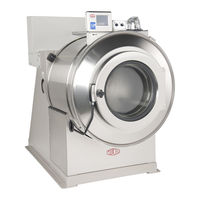
Console, OPL Washer-extractor - 600 to 700 RPM
Brand:
Milnor
| Category:
Washer
| Size: 8 MB
Table of Contents
English
9
Table of Contents
9
Sections
11
Chapter 1. Machine Description, Identification, and Certification
12
About this Milnor Machine-36- or 42- Series, Console, OPL Washer-Extractor - 600 to 700 RPM
12
Functional Description
12
Machine Identification
12
1.2. General Content of the EC-Declaration of Conformity
13
Chapter 2. Safety
15
Safety-Rigid Washer Extractors (Document BIUUUS27)
15
General Safety Requirements-Vital Information for Management Personnel
15
Hazard Information
16
Laundry Facility
16
Maintenance
16
Personnel
16
Safety Devices
16
Safety Alert Messages-Internal Electrical and Mechanical Hazards
17
Safety Alert Messages-Cylinder and Processing Hazards
17
Safety Alert Messages-Unsafe Conditions
18
Damage and Malfunction Hazards
18
Hazards Resulting from Damaged Mechanical Devices
18
Hazards Resulting from Inoperative Safety Devices
18
Careless Operation Hazards-Vital Information for Operator Personnel (See also Operator Hazards Throughout Manual)
19
Careless Servicing Hazards-Vital Information for Service Personnel (See also Service Hazards Throughout Manuals)
19
Careless Use Hazards
19
Prevent Damage from Chemical Supplies and Chemical Systems
20
How Chemical Supplies Can Cause Damage
20
Dangerous Chemical Supplies and Wash Formulas
20
Equipment and Procedures that Can Prevent Damage
22
Use the Chemical Manifold Supplied
22
Close the Line
23
Do Not Let a Vacuum Occur
23
Flush the Chemical Tube with Water
23
Prevent Leaks
23
Put the Chemical Tube Fully below the Machine Inlet
23
Chapter 3. Routine Maintenance
24
Routine Maintenance-36- or 42- Series, Console, OPL Washer-Extractor - 600 to 700 RPM (Document BIUUUM09)
24
How to Show the Maintenance on a Calendar
24
Maintenance Summary
25
How to Remove Contamination
28
Lubricant Identification and Procedures
28
Grease Gun Procedures
29
Procedures for Bearing Components Connected to a Grease Plate
29
Procedures for Motors
30
Français
43
About this Milnor ® Machine-36- ou 42- Séries, Console, OPL Laveur-Extracteur - 600 à 700 RPM
46
Description Fonctionnelle
46
Identification de la Machine
46
Chapitre 1. Description de la Machine
46
Identification, and Certification
46
1.2. Contenu Général du Déclaration CE de Conformité
47
Chapitre 2. Sûreté
49
Sûreté
49
Aménagement de la Blanchisserie
50
Personnel
50
Dispositifs de Sûreté
50
Maintenance
50
Messages D'alerte-Risques Électriques et Mécaniques Internes (Document BIUUUS11)
51
Messages D'alerte-Risques du Tambour et du Fonctionnement (Document BIUUUS13)
51
Messages D'alerte-Conditions Dangereuses
52
Risques des Dommages et des Mauvais Fonctionnements
52
Risques Provenant des Dispositifs de Sécurité Inopérants
52
Risques Résultant de Dispositifs Mécaniques Endommagés
52
Risques des Utilisations Sans Soin
53
Risques de Fonctionnement Sans Sécurité-Information Essentielle pour le Personnel Opérateur (Voir Aussi les Risques des Opérateurs Dans le Livre Technique)
53
Risques de Maintenance Sans Sécurité - Information Essentielle pour le Personnel de Maintenance (Voir Aussi les Risques de Maintenance Dans le Livre Technique)
53
Evitez les Dommages des Produits Chimiques et des Systèmes de Produits Chimiques
54
Comment les Produits Chimiques Peuvent Causer des Dommages
54
Configuration ou Branchement de L'équipement Incorrect
55
Équipement et Procédures Pouvant Éviter les Dommages
57
Utilisez la Tubulure de Produits Chimiques Fournie
57
Fermez la Conduite
58
Ne Laissez Pas un Vide Se Produire
58
Rincez le Tube de Produits Chimiques Avec de L'eau
58
Enfoncez Complètement le Tube de Produits Chimiques Sous L'entrée de la Machine
58
Prévention Contre les Fuites
58
Chapitre 3. Entretien de Routine
60
Entretien de Routine-36- ou 42- Séries, Console, OPL Laveur-Extracteur - 600 à 700 RPM (Document BIUUUM09)
60
Comment Afficher le Calendrier D'entretien
60
Résumé de L'entretien
61
Comment Supprimer la Contamination
65
Deutsch
79
Kapitel 1. Maschinenbeschreibung, Kennzeichnung und Zertifizierung
82
Über diese Milnor Maschine-OPL-Waschschleudermaschine in
82
1.2. Allgemeine Inhalt der EC Konformitaetserklaerung
83
2.1. Sicherheit-Starre Waschmaschinenabsauger
85
Allgemeine Sicherheitsanforderungen-Lebenswichtige Infos für das Leitende Personal (Dokument BIUUUS04)
85
Wäschereitechnische Anlage
86
Personal
86
Sicherheitseinrichtungen
86
Gefahreninformationen
86
Wartung
86
Sicherheitswarnmeldungen-Gefahren Innerhalb der Elektrik und Mechanik (Dokument BIUUUS11)
87
Sicherheitswarnmeldungen-Gefahren durch Trommel und Behandlungsvorgänge (Dokument BIUUUS13)
87
Sicherheitswarnmeldungen-Gefährliche Bedingungen
88
Gefahren durch Schäden und Fehlfunktionen
88
Gefahren durch Beschädigte Teile der Mechanik
88
Gefahren durch Betriebsunfähige Sicherheitseinrichtungen
88
Gefahren durch Unvorsichtige Anwendung
89
Gefahren durch Unvorsichtige Instandsetzung-Lebenswichtige Infos für das Instandsetzungspersonal
89
Gefahren durch Unvorsichtigen Betrieb-Lebenswichtige Infos für das Bedienpersonal (Beachten Sie Bitte Auch die IM Handbuch Erklärten Gefahren für den Bediener)
89
Kapitel 2. Sicherheit
85
Vermeiden von Schäden durch Chemische Betriebsmittel und Systeme
90
Wie Chemische Betriebsmittel Schaden Anrichten können
90
Gefährliche Chemische Betriebsmittel und Waschrezepturen
90
Ausrüstung und Verfahren, die Schaden Verhindern können
92
Die Benutzung des Chemikalien Sammelrohrs
92
Leitung Schließen
93
Lassen Sie kein Vakuum zu
93
Spülen Sie das Chemische Rohr mit Wasser
93
Bringen Sie das Chemische Rohr Vollständig unter dem Maschinenzufluss an
93
Lecks Verhindern
93
Kapitel 3. Regelmäßige Wartung
94
Regelmäßige Wartung
94
Planung des Wartungskalenders
94
Wartungsüberblick
95
Tabelle 1: Eintragung der Markierungen IM Kalender
95
Tabelle 2: Abdeckungen und Zugehörige Teile
95
Tabelle 3: Filter, Vorfilter und Empfindliche Teile
96
Tabelle 4: Verschleißanfällige Komponenten
96
Tabelle 5: Lager und Buchsen für Motoren Siehe Tabelle
96
Milnor 42030V6Z Operator's Manual (110 pages)
MilTouch Controller
Brand:
Milnor
| Category:
Controller
| Size: 7 MB
Table of Contents
English
9
Table of Contents
9
Chapter 1. How to Use the Miltouch ™ Control
13
Using the Miltouch Control
13
The Home Display
13
The Wash Formula Maintenance Display
14
To Change an Existing Wash Formula
15
To Add a New Wash Formula
16
The Configuration Display
17
The Machine Configure Decisions
17
To Erase a Wash Formula
17
The Data Transfer Display
19
The Default Formulas by Laundry Type
19
Controller
21
Data Transfer with the Miltouch Programmer Software
21
How to Mount a USB Flash Drive to the Machine
21
How to Save and Transfer Wash Formulas
21
How to Save Machine Configuration Files
21
How to Transfer Machine Configuration Files to a Miltouch Machine
21
The Data Log Displays
22
The Date Selection Display
22
The Production Display
22
The Configuration and Programming Display
23
The Errors Display
23
The Inputs and Outputs Displays
24
The Run Display
26
The Names and Timers on the Run Display
26
The Machine Status Data
27
Chapter 2. How to Update the Machine Software
29
Miltouch Update: WUMTGUI/2.1
29
Does My Machine Need this Update
29
How Do I Save My Formulas and Machine Configuration
30
How Do I Update the Machine Software
31
Chapter 3. Miltouch ™ Wash Formulas
33
Miltouch Formula Decisions (Document BICLJP02)
33
Type = Type of Step
33
Time = Step Duration
33
Temp = Commanded Bath Temperature (Optional)
33
Hot = Hot Water Valve
33
Cold = Cold Water Valve
34
Third Water Valve (Optional)
34
Level = Bath Level
34
Steam (Optional)
34
C = Chemicals
34
W = When to Inject Chemicals
35
Chemical Dose = Chemical Injection Duration
35
Wash Speed
35
How to End Formula
36
Chapter 4. Troubleshooting
41
Door Opened
41
Vibration Switch Tripped
41
Too Long to Fill
41
Too Long to Drain
42
3-Wire Circuit Disabled
42
Too Long to Steam
42
Too Long to Cool
43
Check Temperature Probe(S)
43
Level Made after Drain
43
Serial Communication Failure
43
Failed Speed Sensor
43
Inverter Tripped
44
External Fault Error
44
Brake Pressure Fault
44
Bearing Pressure Fault
44
Check Flow Meter
44
Tank Pump Ol Tripped
44
Recirc Pump Ol Tripped
44
Loading Aborted
45
Discharge Aborted
45
Invalid Formula
45
Load Eye Blocked
45
Up Lock Not Made
45
Invalid Work Order
45
Invalid Goods Code
45
Invalid Customer Code
45
Can't Find Data
45
Accumulator was Reset
45
Outputs
47
Miltouch 2 (WUMTGUIA 2.X)
48
Inputs
50
Components of the Miltouch ™ Controller Circuit Boards
50
Processor Board (P/N: 08BHPAR91_)
51
Input/Output Board (P/N: 08BHF120A_)
52
4.4. Out-Of-Balance Detection System
53
Requirements
53
Testing
54
Deutsch
61
Abschnitte
62
Kapitel 1. Verwendung der Steuerung Miltouch
66
Verwenden der Miltouch ™ -Steuerung
66
Die Home Anzeige
66
Die Wash Formula Maintenance Anzeige
67
So Ändern Sie eine Bestehende Waschformel
68
Zum Hinzufügen einer Neuen Waschformel
70
Zum Löschen einer Waschformel
70
Die Konfigurations-Azeige
71
Die Maschinenkonfigurations-Entscheidungen
71
Die Standardformeln nach Wäschereityp
73
Die Data Transfer Anzeige
74
Datentransfer mit der Miltouch Programmier-Software
75
So Speichern Sie Dateien mit Maschinenkonfigurationen
75
Wie ein USB-Flashdrive an die Maschinensteuerung Angeschlossen wird
75
Die Datenauswahl-Anzeige
76
So werden Waschformeln Gespeichert und Übertragen
76
So Übertragen Sie Maschinenkonfigurationsdaten auf eine Miltouch Maschine
76
Die Anzeige Konfiguration und Programmierung
77
Die Produktions-Anzeige
77
Die Fehler-Anzeige
78
Die Anzeige Inputs and Outputs
78
Die Betrieb Anzeige (Dokument BICLJO01)
80
Die Bezeichnungen und Timer auf der Betrieb Anzeige
81
Die Maschinenstatus-Daten
81
Die Betriebszustände der Maschine
82
Die Standard- und Popup-Steuerelemente in der Betriebsanzeige
82
Aktualisierung Miltouch: WUMTGUI/2.1
84
Braucht meine Maschine diese Aktualisierung
84
Wie kann ich meine Formeln und Maschinenkonfigurationen Speichern
85
Wie Aktualisiere ich die Maschinensoftware
87
Wie kann ich meine Formeln und Konfigurationen wieder Herstellen
87
Kapitel 2. Wie wird die Maschinensoftware Aktualisiert
84
Entscheidungen Miltouch-Formeln (Dokument BICLJP02)
88
Type = Typ des Schrittes
88
Time = Schrittdauer
88
Hot = Heißwasserventil
88
Cold = Kaltwasserventil
89
Drittwasser-Ventil (Option)
89
Level = Laugen-Füllhöhe
89
Dampf (Optional)
89
W = Wann die Chemikalie Eingespritzt wird
90
Chemical Dose = Einspritzdauer der Chemikalie
90
Signal bei Chemikalien-Einspritzung
90
Wash Speed
90
Art des Entleerens
90
Re-Use Drain (Optional)
91
Beenden einer Formel
91
Kapitel 3. Miltouch ™ Waschformeln
88
Rinsave ™ Formeln für Gewerbliche Wäschereien
91
Kapitel 4. Fehlersuche
96
Miltouch ™ und Miltouch-EX ™ Fehlermeldungen
96
Tür Offen
96
Schwingungsschalter Ausgelöst
96
Zu Lang für Ablassen
97
3-Anschlüsse Ausgeschaltet
97
Zu Lang für Dampf
97
Zu Lang zu Abkühlen
98
Temperaturfühler Überprüfen
98
Wasser in der Maschine nach dem Ablassen
98
Fehler Serielle Kommunikation
98
Geschwindigkeitssensor Versagt
98
Frequenzumwandler Ausgelöst
99
Externer Fehler
99
Fehler Bremsdruck
99
Fehler Lagerdruck
99
Durchflussmesser Überprüfen
99
ÜL Tankpumpe Ausgelöst
99
ÜL Umlaufpumpe Ausgelöst
99
Beladung Abgebrochen
100
Entladen Abgebrochen
100
Ungültige Formel
100
Fotozelle Beladung Blockiert
100
Sperre Oben nicht Eingerastet
100
Ungültiger Arbeitsauftrag
100
Ungültiger Wäschestück-Code
100
Ungültiger Kunden-Code
100
Ungültiger Angestellten-Code
100
Daten können nicht Gefunden werden
100
Ausgänge
102
Miltouch 3 (WUMTGUIA 3.X)
102
Miltouch 2 (WUMTGUIA 2.X)
103
Eingänge
104
Komponenten der Miltouch ™ Controller-Leiterplatte
105
Prozessorkarte (Teilenr.: 08BHPAR91_)
105
Eingangs-/Ausgangskarte (Teilenr.: 08BHF120A_)
106
Unwucht-Erkennungssystem (Dokument BICLUT04)
107
Anforderungen
107
Advertisement
Milnor 42030V6Z Mechanical Parts And Service (116 pages)
Brand:
Milnor
| Category:
Laundry Appliance
| Size: 8 MB
Table of Contents
Table of Contents
3
36021V5J, V5Z, V7Z; 36026V5J, V5Z, V7Z; 42026V5J, V6Z
6
General Service & Safety-Related Components
7
Limited Standard Warranty
8
How to Get the Necessary Repair Components
9
Trademarks
9
Safety - Rigid Washer Extractors
10
Safety Alert Messages-Internal Electrical and Mechanical Hazards
10
Safety Alert Messages-Cylinder and Processing Hazards
10
Table 1 Trademarks
10
Safety Alert Messages-Unsafe Conditions
12
Damage and Malfunction Hazards
12
Hazards Resulting from Inoperative Safety Devices
12
Hazards Resulting from Damaged Mechanical Devices
12
Careless Use Hazards
13
Careless Operation Hazards-Vital Information for Operator Personnel (See also Operator Hazards Throughout Manual)
13
Careless Servicing Hazards-Vital Information for Service Personnel (See also Service Hazards Throughout Manuals)
13
Safety Placard Use and Placement 36021CPE, NSP, V5J, V5Z and 36026V5J, V5Z
16
36021CPE, NSP, V5J, V5Z and 36026V5J, V5Z
18
36021V7J, V7Z; 36026V7J/W, V7Z; 42026V5J; 42026V6J/W, V7Z; 42030V6J, V6Z
20
Safety Placard Use and Placement-ISO
22
36021V7J, V7Z; 36026V7J/W, V7Z; 42026V5J; 42026V6J/W, V6Z; 42030V6J, V6Z
22
Guards & Covers 36021V5Z, 36026V5Z
24
Guards & Covers 36021V7Z, 36026V7Z, 42026V5J, 42026V6Z, 42030V6Z
26
Figure 1 Front Covers
26
Figure 2 Rear Covers and Side Gasket
27
Torque Requirements for Fasteners
28
Torque Values
28
Fasteners Made of Carbon Steel
28
Without a Threadlocker
28
Figure
28
Table 8 Torque Values for Standard Fasteners with Maximum 5/16-Inch Diameters and no Lubricant
28
Table 9 Torque Values for Standard Fasteners Larger than 5/16-Inch Diameters and no Lubricant
29
Table 10 Torque Values for Plated Fasteners with Maximum 5/16-Inch Diameters and no Lubricant
29
With a Threadlocker
30
Table 11 Torque Values for Plated Fasteners Larger than 5/16-Inch Diameters and no Lubricant
30
Stainless Steel Fasteners
32
Preparation
33
How to Apply a Threadlocker
34
Blind Holes
34
Through Holes
34
Figure 4 Apply Threadlocker in a Blind Hole
34
Figure 5 Apply Threadlocker in a through Hole
35
Drive Assemblies
36
Drive Chart 36021V5J, 36021V5Z, 36026V5J, 36021V5Z
38
Drive Chart 36021V7J, 36021V7Z, 36026V7J, 36026V7Z
40
Drive Chart 42026V5J, 42026V6J, 42026V6Z, 42030V6J, 42030V6Z
42
Drive Pulley and Belt Maintenance
44
Pulley Requirements
44
Condition of Grooves on Pulleys
44
Pulley and Shaft Position
45
Keep Run-Out in Tolerance
46
Belt Requirements
47
Condition of Belts
47
Tension of Belts
48
The Pulleys Must Stay Aligned When You Adjust the Belt Tension
49
How to Do Maintenance on Pulleys and Belts
50
Typical Steps to Replace Pulleys and Belts
50
Run-Out
50
Examples of Procedures Used at the Milnor Factory to Align
51
Pulleys
51
Motor Mount 30015, 30022, 36021, 36026, 42026, & 42030Vxx,Txx
53
Bearing Assembly 36021V5J, 36021V5Z, 36026V5J, 36026V5Z with Starplate
56
Bearing Assembly 36021V7Z, 36026V7Z, 42026V5J, 42026V6Z, 42030V6Z
59
Cylinder & Shell
63
Main Bearing, Shell, Cylinder Installation
64
36021V5J, 36021V5Z, 36026V5J, 36026V5Z with Starplate
64
36021V7Z, 36026V7Z, 42026V5J, 42026V6Z, 42030V6Z
69
Cross Section of Shell, Cylinder, Bearing, and Frame
69
Main Bearing, Shell, and Cylinder Installation
70
20 Inch Door Assemblies after 8/2016
73
42030V6Z
74
Mcr12; Mct16/18/27; Mwf18/27; Mwr27/36; Mwt12/16/18/27; 3015/3022T6X, Vrj, V8Z, Vzz; 3022X8R; 36021V5J, V5Z, V7Z; 36026V5J, V5Z, V7Z
78
42026V5J, V6Z. 42030V6Z
78
Door Lock Mechanisms
79
Door Handle and Lock Actuator
81
Door Handle and Lock Actuator
82
Chemical Supply Devices
84
42030V6Z
88
Soap Chute 36021V5J, V5Z, V7Z; 36026V5J, V5Z, V7Z; 42026V5J, V6Z; 42030V6Z
88
42030V6Z
90
Supply Chute
90
Valve Manifold
91
Water & Steam
94
Water Schematic 36021V5J, V5Z, V7Z; 36026V5J, V5Z, V7Z; 42026V5J, V6Z; 42030V6Z
96
42030V6Z
98
Steam Inlet 36021V5J, V5Z, V7Z; 36026V5J, V5Z, V7Z; 42026V5J, V6Z; 42030V6Z
104
Drain Valve 36021V5J, V5Z, V7Z; 36026V5J, V5Z, V7Z; 42026V5J, V6Z; 42030V6Z
106
Inch Electrical Drain Valve
108
Control & Sensing
110
42030V6Z
111
36021V5J, V5Z, V7Z; 36026V5J, V5Z, V7Z; 42026V5J, V6Z; 42030V6Z
112
Vibration Safety Switch Adjustments
114
What the Vibration Safety Switch Does
114
Adjustments
114
Vibration Safety Switch
116
Milnor 42030V6Z Installation Manual (56 pages)
Brand:
Milnor
| Category:
Washer
| Size: 9 MB
Table of Contents
Table of Contents
3
General Information
6
Limited Standard Warranty
7
How to Get the Necessary Repair Components
8
Trademarks
8
Safety - Rigid Washer Extractors
9
Safety Alert Messages-Internal Electrical and Mechanical Hazards
9
Safety Alert Messages-Cylinder and Processing Hazards
9
Safety Alert Messages-Unsafe Conditions
10
Damage and Malfunction Hazards
10
Hazards Resulting from Inoperative Safety Devices
10
Hazards Resulting from Damaged Mechanical Devices
11
Careless Use Hazards
12
Careless Operation Hazards-Vital Information for Operator Personnel (See also Operator Hazards Throughout Manual)
12
Careless Servicing Hazards-Vital Information for Service Personnel
12
(See also Service Hazards Throughout Manuals)
12
Installation Tag Guidelines
13
Important Installation Precautions
16
External Fuse/Breaker, Wiring, and Disconnect Requirements
16
Fuse or Circuit Breaker Size
16
If a Fuse Is Used
16
If a Standard Circuit Breaker Is Used
16
If an Inverse Time Circuit Breaker Is Used
16
Wire Size
16
Ground
17
Disconnect Switch for Lockout/Tagout
17
Using GFCI (Ground Fault Circuit Interrupter) Device
17
Machines
17
Disclaimer of Responsibility
18
Major Design Considerations
18
Primary Information Sources
19
Prevent Damage from Chemical Supplies and Chemical Systems
19
Figure 1 How Rotating Forces Act on the Foundation
19
How Chemical Supplies Can Cause Damage
20
Dangerous Chemical Supplies and Wash Formulas
20
Incorrect Configuration or Connection of Equipment
20
Figure 2 Incorrect Configurations that Let the Chemical Supply Go in the Ma
21
Equipment and Procedures that Can Prevent Damage
22
Use the Chemical Manifold Supplied
22
Figure 3 Incorrect Configurations that Let the Chemical Supply Go in the Ma
22
Figure 4 Examples of Manifolds for Chemical Tubes. Your Equipment Can Look
22
Close the Line
23
Do Not Let a Vacuum Occur
23
Flush the Chemical Tube with Water
23
Put the Chemical Tube Fully below the Inlet
23
Prevent Leaks
23
Figure 5 a Configuration that Prevents Flow in the Machine When the Pump Is off (if the Chemical Tube and Tank Have no Pressure)
23
Installation Procedures
24
Handling a Washer-Extractor from Delivery to Final Location
24
Notices
24
Qualified Personnel Only
24
Disclaimer
24
Other Tasks
24
Facility Prerequisites
25
Rigger Precautions
25
Technician Precautions
27
Can the Door(S) be Opened before Utilities Are Connected
29
Connection Precautions for Washer-Extractors
29
Notices
30
Machine Must be Anchored
30
Utility Requirements and Related Information
30
Plumber Precautions
31
Electrician Precautions
32
Chemical Supplier Precautions
33
Dimensional Drawings
34
Bd3621V5Jae/2022252 - 36021V5J
35
BD3621V5JAB/2022252 - 36021V5J (Options)
36
Bd3621V5Zbe/2015462 - 36021V5Z
37
BD3621V5ZBB/2020034 - 36021V5Z Options
38
Bd3621V7Zbe/2017134 - 36021V7Z
39
BD3621V7ZBB/2020034 - 36021V7Z Options
40
Bd3626V5Jae/2022252 - 36026V5J
41
BD3626V5JAB/2022252 - 36026V5J (Options)
42
Bd3626V5Zbe/2021103 - 36026V5Z
43
BD3626V5ZBB/2020034 - 36026V5Z Options
44
Bd3626V7Zbe/2017134 - 36026V7Z
45
BD3626V7ZBB/2020034 - 36026V7Z Options
46
Bd4226V5Jae/2022252 - 42026V5J
47
BD4226V5JAB/2022252 - 42026V5J (Options)
48
Bd4226V6Zbe/2022424 - 42026V6Z
49
BD4226V6ZBB/2020034 - 42026V6Z Options
50
Bd4230V6Zbe/2019416 - 42030V6Z
51
BD4230V6ZBB/2020034 - 42030V6Z Options
52
Dimensional Drawings: Pedestals
53
BD36V5BSBE/2013063 - 36021/36026V5J, V5Z (Pedestal)
55
BD42V6BSAE/2013064 - 3621/3626V7J, V7Z; 4226/4230V6J, V6Z (Pedestal)
56
Milnor 42030V6Z Service (103 pages)
Brand:
Milnor
| Category:
Washer
| Size: 5 MB
Table of Contents
Table of Contents
3
Limited Standard Warranty
5
How to Get the Necessary Repair Components
6
Trademarks
7
Safety—Rigid Washer Extractors
8
Guards & Covers 36021V5Z, 36026V5Z
13
Guards & Covers 36021V7Z, 36026V7Z, 42026V6Z
15
Prevent Damage from Chemical Supplies and Chemical
22
Service and Maintenance
35
Torque Requirements for Fasteners
36
Drive Assemblies
45
Motor Mount
49
Bearing Assemblies
53
42030V6Z
62
42030V6Z
63
42030V6Z
64
Inch Door Assemblies after 8/2016
65
Flat Front Door
66
Door Lock Mechanism
69
Door Handle and Lock Actuator
72
71 5. Chemical and Supply Devices
75
Soap Chute
76
Peristaltic Supply Assembly
77
Compartment Supply
80
Water Piping Assemblies
83
Water Schematic
85
Water Inlet Assemblies
87
Steam Inlet
91
Drain Valve
93
Inch Electric Drain Valve
95
Control and Sensing Assemblies
97
Vibration Safety Switch Adjustments
98
Temperature Probe
101
Level Sensing
102
Milnor 42030V6Z Service Manual (117 pages)
Washer-Extractors
Brand:
Milnor
| Category:
Washer
| Size: 7 MB
Table of Contents
Table of Contents
4
73 5. 20 Inch Door Assemblies after 8/2016
77
20" Flat Front Door
78
Door Lock Mechanism
81
Door Handle and Lock Actuator
84
83 6. Chemical and Supply Devices
87
Peristaltic Supply Assembly
89
Water Piping Assemblies
97
Water Schematic
99
Water Inlet Assemblies
101
Steam Inlet Assembly
106
Drain Valve Installation
108
Inch Electric Drain Valve
109
Control and Sensing Assemblies
111
Vibration Safety Switch Adjustments
112
Temperature Probe
115
Level Sensing
116
Milnor 42030V6Z Maintenance Manual (38 pages)
Washer-extractor, Rigid Console, Grease Bearings, _V6Z, _V7Z
Brand:
Milnor
| Category:
Washer
| Size: 3 MB
Table of Contents
Table of Contents
8
Machine Description and Identification
11
About this Manual and Your Milnor® Machine
11
Description
11
Machine Identification
11
Machine Data Plate
11
Figure 1 Machine Data Plate
11
Safety
12
Safety - Rigid Washer Extractors
12
Safety Alert Messages-Internal Electrical and Mechanical Hazards
12
Safety Alert Messages-Cylinder and Processing Hazards
12
Safety Alert Messages-Unsafe Conditions
14
Damage and Malfunction Hazards
14
Hazards Resulting from Inoperative Safety Devices
14
Hazards Resulting from Damaged Mechanical Devices
14
Careless Use Hazards
15
Careless Operation Hazards-Vital Information for Operator Personnel (See also Operator Hazards Throughout Manual)
15
Careless Servicing Hazards-Vital Information for Service Personnel (See also Service Hazards Throughout Manuals)
15
Prevent Damage from Chemical Supplies and Chemical Systems
16
How Chemical Supplies Can Cause Damage
16
Dangerous Chemical Supplies and Wash Formulas
16
Incorrect Configuration or Connection of Equipment
16
Figure 2 Incorrect Configurations that Let the Chemical Supply Go in the Ma
17
Equipment and Procedures that Can Prevent Damage
18
Use the Chemical Manifold Supplied
18
Figure 3 Incorrect Configurations that Let the Chemical Supply Go in the Ma
18
Figure 4 Examples of Manifolds for Chemical Tubes. Your Equipment Can Look
18
Close the Line
19
Do Not Let a Vacuum Occur
19
Flush the Chemical Tube with Water
19
Put the Chemical Tube Fully below the Inlet
19
Prevent Leaks
19
Figure 5 a Configuration that Prevents Flow in the Machine When the Pump Is off (if the Chemical Tube and Tank Have no Pressure)
19
Routine Maintenance
20
Maintenance Summary
20
Guards and Related Components
21
Filters, Screens, and Sensitive Components
21
Table 1 Guards and Related Components
21
Table 2 Filters, Screens, and Sensitive Components
21
Components that Become Worn
22
Bearings and Bushings
22
Motor Grease Schedule
22
Mechanisms and Settings
22
Table 3 Components that Become Worn
22
Table 4 Bearings and Bushings
22
How to Remove Contamination
23
Lubricant Identification
24
Grease Gun Procedures
25
Procedures for Bearing Components Connected to a Grease Plate
25
Procedures for Motors
26
Figure 6 Motor Grease Maintenance Conditions
27
How to Show the Maintenance on a Calendar
28
Maintenance Components-Machines and Controls Group
29
How to Examine V-Belts and Pulleys
29
Figure 7 Belt and Pulley Conditions to Look for
29
Figure 8 How to Adjust Belt Tension on a Machine that Uses Spring Tension
30
Inverters
31
Chemical Devices
31
Figure 9 Electric Box and Inverter. These Are Examples. Your Machine Can Look
31
Water and Steam Devices
32
Figure 10 Chemical Inlet Manifolds for Chemical Pump Systems. See Caution
32
Figure 11 Soap Chute and Optional 5-Compartment Supply Injector. These Are Ex
32
Figure 12 Air Tube for the Water Level Sensor. These Are Examples. Your Ma- Chine Can Look Different
33
Figure 13 Water Pressure Regulator for Chemical Flush. These Are Examples
33
How to Examine Compressed Air Mechanisms
34
Figure 14 Steam Inlet Strainer. These Are Examples. Your Machine Can Look Different
34
Figure 15 Compressed Air Inlet Strainers. These Are Examples. Your Machine Can Look Different
34
Figure 16. Self-Purging Air Line Filter to Remove Moisture and Other Contamination. These Are Examples. Your Machine Can Look Different
35
How to Do a Test of Emergency Stop Mechanisms
36
Figure 17 Compressed Air Mechanisms These Are Examples. Your Machine Can Look Different
36
Maintenance Components-Large Extractors
38
Lubricant Maintenance for Grease-Filled Drive Bearings
38
Figure 18 Grease Ports for Grease-Only Bearing Assembly
38
Milnor 42030V6Z Operator's Manual (34 pages)
Brand:
Milnor
| Category:
Washer
| Size: 1 MB
Table of Contents
Table of Contents
8
1 Preface
10
About this Operator Guide and this Miltouch™ Washer-Extractor
10
2 Controls
11
Physical Controls
11
Figure 1 Control Panel
11
Figure 2 Control Panel
11
Emergency Stop Switch (Locking Push Button)
12
Figure 3 Emergency Stop Switch
12
How to Use the Miltouch™ Controller
13
The Home Display
13
Figure 4 the Home Display
14
3 Normal Operation
15
Safety and Best Practice When Loading and Unloading
15
Loading and Unloading Safety
15
Load Size Best Practice
15
Weighing Goods
16
Apply Control Power
16
Open the Door (Turn-Knob)
17
Open the Door (Push-Plate)
17
Load the Cylinder
17
Close the Door
17
Figure 5 Door with a Turn-Knob
17
Figure 6 Door with a Push-Plate
17
Start the Wash Formula
18
To Run a Wash Formula Locally
18
To Run a Wash Formula from the Mildata Computer
18
Figure 7 Remote Formula Window
18
About the Mildata ® Product and Production Data
19
Monitor the Wash Formula
20
The Run Display
20
The Names and Timers Area (A)
20
Figure 8 the Three Information Areas of the Run Display
20
Figure 9 the Names and the Timers Area
20
The Machine Status Area (B)
21
How to Monitor Automatic Liquid-Chemical Injections
21
Manual Control and Diagnostics Area (C)
21
Figure 10 the Machine Status Area
21
Figure 11 Chemicals from Valves 1 and 2 Injecting
21
Respond to the End of the Cycle
22
Open the Door and Unload the Cylinder
22
Figure 12 Standard Controls
22
4 Troubleshooting
23
Operator Intervention
23
Chemical Supplies Intervention
23
Error Intervention
24
Formula Intervention
24
Figure 13 Chemical Injection Dialog Box
24
Figure 14 Formula Control Areas
25
Figure 15 Pop-Up Controls for Step Timer
25
Modify Step Timer
25
Figure 16 Pop-Up Controls for Water Valves
26
Figure 17 Pop-Up Controls for Drain Valves
26
Modify Drain Valves
26
Modify Water Valves
26
Figure 18 Pop-Up Controls for Steam and Cooldown Valves
27
Figure 19 Pop-Up Controls for Cylinder Speed
27
Figure 20 Pop-Up Controls for Water Temperature
27
Modify Cylinder Speed
27
Modify Steam and Cooldown
27
Modify Water Temperature
27
Modify Water Level
28
To Cancel a Formula
28
Figure 21 Pop-Up Controls for Water Level
28
Figure 22 Resume or Cancel the Formula
28
Errors
29
Miltouch™ Error Messages
29
Figure 23 Sample Error Code Dialog Box
29
Figure 24 Transducer Tube
30
Figure 25 Schematic of Typical Drain Circuit
30
Error Correction
32
Figure 26 Error Causes/Solutions Display
33
How to Contact Milnor
34
Pellerin Milnor ® Corporation Contact Information
34
Advertisement
Related Products
Milnor 42030V6J
Milnor 42030V Series
Milnor 42032X7R
Milnor Staphguard 42031 CP3
Milnor Staphguard 42031 NP3
Milnor Staphguard 42031 SP2
Milnor Staphguard 42031 WP3
Milnor Staphguard 42031 WP2
Milnor Staphguard 42031 SP3
Milnor Staphguard 42031 CP2
Milnor Categories
Washer
Industrial Equipment
Controller
Laundry Appliance
Dryer
More Milnor Manuals
Login
Sign In
OR
Sign in with Facebook
Sign in with Google
Upload manual
Upload from disk
Upload from URL