Sign In
Upload
Manuals
Brands
Michell Instruments Manuals
Measuring Instruments
S8000
Michell Instruments S8000 Manuals
Manuals and User Guides for Michell Instruments S8000. We have
2
Michell Instruments S8000 manuals available for free PDF download: User Manual
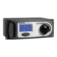
Michell Instruments S8000 User Manual (98 pages)
Integrale Chilled Mirror Hygrometer
Brand:
Michell Instruments
| Category:
Measuring Instruments
| Size: 4 MB
Table of Contents
Table of Contents
4
Safety
8
Electrical Safety
8
Pressure Safety
8
Toxic Materials
8
Repair and Maintenance
8
Calibration
8
Safety Conformity
8
Abbreviations
9
Warnings
9
1 Introduction
11
Figure 1 S8000 - Horizontal Model
11
Operating Principle
12
Figure 2 Operating Principle
13
2 Installation
14
Safety
14
Unpacking the Instrument
14
Figure 3 S8000 Integrale Packing
14
Figure 4 S8000 Accessories
15
Operating Requirements
16
Environmental Requirements
16
Electrical Requirements
16
Exterior Layout
17
Table 1 Front Panel Controls and Indicators
18
Figure 5 Front Panel
18
Table 2 Rear Panel Controls and Indicators
19
Figure 6 Rear Panel
19
Rear Panel Connections (All Versions)
20
Power Supply Input
20
Figure 7 Power Supply Input
20
Analog Output Connections
21
Figure 8 Analog Output Connectors
21
Alarm Output Connections
22
Figure 9 Alarm Output Connectors
23
Remote PRT Probe (Optional)
24
Figure 10 Remote PRT Connection
24
4-Wire PRT Output
25
USB Communications Port Connector
25
Figure 11 Internal PRT Output
25
Figure 12 USB Port Connection
25
Connection of Gas Supplies
26
Figure 13 Gas Connections
26
Conversion of a Horizontal Version to Rack Mount
28
Figure 14 Conversion of Horizontal to Rack Mount
28
Fitting Rack Mounted Version into Rack
29
Figure 15 Rack Fixing Method
29
2.5.10 Fitting the Safety Strap
30
Figure 16 Removing the Blanking Plug
30
Figure 17 Fitting or Removing the Safety Strap
30
3 Operation
31
General Operational Information
31
Function Keys
32
Up and down Arrow Keys
32
Left and Right Arrow Keys
32
Enter or Select Key
32
Figure 18 Function Keys
32
Instrument Display
33
Figure 19 Typical Front
33
Operational Data Display
34
Figure 20 Set-Up Display
34
Operational Status Display
35
Menu Structure
36
Figure 21 Main Menu
36
Figure 22 Menu Structure
37
Operating Cycle
38
Figure 23 Typical Operating Cycle
38
First Time Operation - Operate Mode
39
Figure 24 Main Display
39
Operating Functions
40
DCC - Dynamic Calibration Control
40
Figure 25 Main Menu Display
40
Figure 26 DCC ON/OFF
41
MAXCOOL Function
42
Figure 27 Switching MAXCOOL and MEASURE Mode
42
STANDBY Function
43
Figure 28 Switching STANDBY and OPERATE Mode
43
SETUP Menu
44
Figure 29 Set-Up Menu Selection
44
Figure 30 DCC Sub-Menu Selection
44
Figure 31 Set Parameter Value
44
Table 3 Default Set-Up Parameters
45
Pressure Measurements
46
Logging Function
46
FAST - Frost Assurance Technology
47
External PRT
48
4 Application Software
49
Installation
49
Establishing Communications
49
Figure 32 Communications Setup Screen
49
USB Communication
50
Figure 33 Windows Device Manager Screen
50
Data Acquisition or Edit Variables Mode
51
Figure 34 Options Screen
51
Data Acquisition
52
Table 4 Data Acquisition Control Description
52
Figure 35 Data Acquisition Screen
52
Table 5 Graph Control Description
53
Table 6 Status Bar Description
53
Variable Edit
54
Figure 36 S8000 Series Variables Editor Screen
55
5 Maintenance
56
Safety
56
Fuse Replacement
56
Figure 37 Power Supply Fuse Replacement
56
Fan Filter Cleaning
57
Figure 38 Remove and Replace Fan Filter
57
Sensor Mirror Cleaning
58
Figure 39 Mirror and Optics Cleaning
58
Fitting the Microscope (Optional)
59
Figure 40 Fitting the Microscope
59
6 Good Measurement Practice
60
Sampling Hints
61
7 Calibration
64
Traceability
64
Figure 41 Typical Calibration Certifi Cate
64
8 Preparation for Shipping
65
Figure 42 Instrument Packing Details
65
Appendix A Technical Specifi Cations
67
Figure 43 Select Format
70
Figure 44 Set Format Properties
70
Figure 45 Format Disc
70
Appendix B Formatting SD Cards
70
Appendix C Calculations
72
Water Content
72
Temperature - Dew Point
72
C to °F Calculation
72
RH Calculation
72
Conversion of Bara to Psia and Kpa
73
Figure 46 Modbus Connection
75
Appendix D Modbus RTU Communications
75
Introduction
75
Basic Modbus Operation
75
Modbus RTU Connections and Protocol
76
Register Map
76
Table 7 Modbus Holding Register Map
77
Table 8 Register Confi Guration a
78
Table 9 Register Confi Guration B1
78
Table 10 Register Confi Guration B2
78
Table 11 Register Confi Guration D Status Word
79
Table 12 Register Confi Guration E Units
79
Table 13 Register Confi Guration F Display Setting a
79
Table 14 Register Confi Guration F Display Setting B
80
Table 15 Register Confi Guration H
80
Table 16 Register Confi Guration J
80
Table 17 Register Confi Guration K
80
Table 18 Register Confi Guration L
81
Table 19 Register Confi Guration M
81
Table 20 Register Confi Guration N
81
Table 21 Register Confi Guration P
83
Appendix E Installation of the Application Software
85
Figure 47 Device Manager Screen
86
Figure 48 Communications Window
87
Appendix Feu Declaration of Conformity
89
Appendix G Quality, Recycling & Warranty Information
91
Pressure Equipment Directive (PED) 97/23/EC
91
Recycling Policy
91
WEEE Compliance
91
Rohs2 Compliance
92
Warranty
92
REACH Compliance
93
Calibration Facilities
93
Return Policy
94
Manufacturing Quality
94
Appendix H Return Document & Decontamination Declaration
96
Advertisement
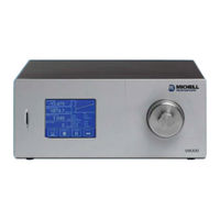
Michell Instruments S8000 User Manual (92 pages)
Chilled Mirror Hygrometer
Brand:
Michell Instruments
| Category:
Measuring Instruments
| Size: 3 MB
Table of Contents
Table of Contents
4
Safety
9
Electrical Safety
9
Pressure Safety
9
Toxic Materials
9
Repair and Maintenance
9
Calibration
9
Safety Conformity
9
Abbreviations
10
Warnings
10
1 Introduction
11
Figure 1 S8000
11
Operating Principle
12
Figure 2 Operating Principle
12
2 Installation
13
Safety
13
Unpacking the Instrument
13
Figure 3 S8000 Packing
13
Operating Requirements
15
Environmental Requirements
15
Electrical Requirements
15
Exterior Layout
15
Table 1 Front Panel Controls and Indicators
16
Figure 4 Front Panel
16
Figure 5 Rear Panel
17
Rear Panel Connections (All Versions)
18
Table 2 Rear Panel Controls and Indicators
18
Power Supply Input
19
Figure 6 Power Supply Input
19
Analog Output Connections
20
Figure 7 Analog Output Connectors
20
Alarm Output Connections
21
Figure 8 Alarm Output Connectors
22
Remote PRT Probe (Optional)
23
Figure 9 Remote PRT Connection
23
4-Wire PRT Output (Optional)
24
USB Communications Port Connector
24
Figure 10 Internal PRT Output (Optional)
24
Figure 11 USB Port Connection
24
Ethernet Port (Optional)
25
RS232/485 Port (Optional)
25
Figure 12 Ethernet Port (Optional)
25
Figure 13 RS232/485 Port (Optional)
25
Connection of Gas Supplies
27
Figure 14 Gas Connections
27
Internal Sample Pump (Optional)
29
Figure 15 Gas Connections When Pump Is Fitted
29
Conversion of S8000 to Rack Mount
30
Figure 16 Rack Fixing Method
30
3 Operation
31
General Operational Information
31
Instrument Display
32
Figure 17 Initialising Overlay Screen
32
Figure 18 Main Screen
32
Main Screen
33
Table 3 Main Screen Description
33
Figure 19 Main Screen Layout
33
Customizable Readouts
34
Operational Status Display
34
Table 4 Operational Status Display
34
Setup Menu Screen
35
Figure 20 Setup Menu Screen
35
Figure 21 Virtual Keyboard
36
Menu Structure
37
Figure 22 Menu Structure
37
DCC
38
Table 5 DCC Parameters
38
Figure 23 DCC Screen
38
Logging
39
Table 6 Logging Parameters
39
Figure 24 Logging Screen
39
Table 7 SD Card Status Indicators
40
Outputs
41
Alarm
41
Table 8 Outputs Parameters
41
Table 9 Alarm Parameters
41
Figure 25 Outputs Screen
41
Figure 26 Alarm Screen
41
3.2.10 Display
42
Table 10 Display Parameters
42
Figure 27 Display Screen
42
3.2.11 Clock
43
ABOUT (Network Settings)
43
Table 11 Clock Parameters
43
Table 12 Network Parameters
43
Figure 28 Clock Screen
43
Figure 29 Network Settings Screen
43
Operational Functions
44
Operating Cycle
44
Figure 30 Typical Operating Cycle
44
Operating Guide
45
DCC - Dynamic Contamination Control
45
MAXCOOL Function
46
Pressure Compensation
46
Data Logging
46
Frost Assurance System Technology (FAST)
47
STANDBY Mode
47
4 Application Software
48
Installation
48
Establishing Communications
48
Figure 31 Communications Setup Screen
48
USB Communication
49
Figure 32 Windows Device Manager Screen
49
RS232/485 Communication
50
Ethernet Communication
50
Figure 33 Network Settings Screen
50
Data Acquisition or Edit Variables Mode
51
Figure 34 Options Screen
51
Data Acquisition
52
Table 13 Data Acquisition Control Description
52
Figure 35 Data Acquisition Screen
52
Table 14 Graph Control Description
53
Table 15 Status Bar Description
53
Variable Edit
54
Figure 36 Variables Editor Screen
55
5 Maintenance
56
Safety
56
Fuse Replacement
57
Figure 37 Power Supply Fuse Replacement
57
Sensor Mirror Cleaning
58
Figure 38 Sensor Mirror Cleaning
58
Releasing Optics Window
59
Figure 39 Releasing Optics Window
59
Fitting the Microscope (Optional)
60
Figure 40 Fitting the Microscope
60
6 Good Measurement Practice
61
Sampling Hints
62
7 Calibration
65
Traceability
65
Figure 41 Typical Calibration Certifi Cate
65
8 Preparation for Shipping
66
Figure 42 Instrument Packing Details
66
Appendix A Technical Specifi Cations
68
Dimensions
70
Figure 43 Select Format
72
Figure 44 Set Format Properties
72
Figure 45 Format Disc
72
Appendix A Technical Specifi Cations
72
Appendix B Formatting SD Cards
72
Appendix C Calculations
73
Water Content
74
Temperature - Dew Point
74
C to °F Calculation
74
RH Calculation
74
Conversion of Bara to Psia and Kpa
75
Figure 46 Modbus Connection
77
Appendix D Modbus RTU Communications
77
Introduction
77
Basic Modbus Operation
77
Modbus RTU Connections and Protocol
78
Register Map
78
Table 16 Modbus Holding Register Map
79
Table 17 Register Confi Guration a
80
Table 18 Register Confi Guration B1
80
Table 19 Register Confi Guration B2
80
Table 20 Register Confi Guration D Status Word
81
Table 21 Register Confi Guration E Units
81
Table 22 Register Confi Guration F Display Setting a
81
Table 23 Register Confi Guration F Display Setting B
82
Table 24 Register Confi Guration H
82
Table 25 Register Confi Guration J
82
Table 26 Register Confi Guration K
82
Table 27 Register Confi Guration L
83
Table 28 Register Confi Guration M
83
Table 29 Register Confi Guration N
83
Table 30 Register Confi Guration P
84
Appendix E Default Values
86
Appendix F Quality, Recycling & Warranty Information
88
Appendix G Return Document & Decontamination Declaration
90
Advertisement
Related Products
Michell Instruments SF52
Michell Instruments SF82 Series
Michell Instruments SF82 M12
Michell Instruments SF82 MiniDIN 43650
Michell Instruments S904
Michell Instruments S904D
Michell Instruments SF72
Michell Instruments S4000 TRS
Michell Instruments S-535
Michell Instruments Cermet II
Michell Instruments Categories
Measuring Instruments
Transmitter
Analytical Instruments
Laboratory Equipment
Accessories
More Michell Instruments Manuals
Login
Sign In
OR
Sign in with Facebook
Sign in with Google
Upload manual
Upload from disk
Upload from URL