Sign In
Upload
Manuals
Brands
Marvell Manuals
Controller
Integrated Controller 88F6281
Marvell Integrated Controller 88F6281 Manuals
Manuals and User Guides for Marvell Integrated Controller 88F6281. We have
1
Marvell Integrated Controller 88F6281 manual available for free PDF download: Hardware Specifications
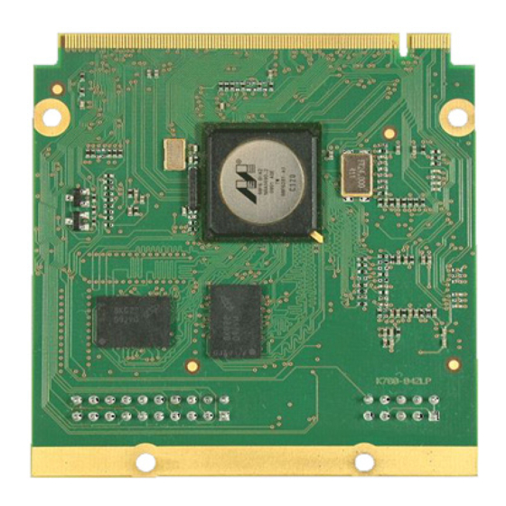
Marvell Integrated Controller 88F6281 Hardware Specifications (140 pages)
Integrated Controller
Brand:
Marvell
| Category:
Controller
| Size: 1 MB
Table of Contents
Hardware Specifications
1
Document Status
2
Product Overview
3
Features
4
Table of Contents
8
List of Tables
10
List of Figures
13
Preface
15
About this Document
15
Related Documentation
15
Document Conventions
16
Pin and Signal Descriptions
17
Pin Logic
18
Figure 1: 88F6281 Pin Logic Diagram
18
Pin Descriptions
19
Pin and Signal Descriptions
19
Table 1: Pin Functions and Assignments Table Key
19
Table 2: Interface Pin Prefix Codes
19
Power Supply Pins
21
Table 3: Power Pin Assignments
21
Table 4: Miscellaneous Pin Assignments
23
Table 5: DDR SDRAM Interface Pin Assignments
24
Table 6: PCI Express Interface Pin Assignments
26
Table 7: SATA Port Interface Pin Assignment
27
Table 8: Gigabit Ethernet Port0/1 Interface Pin Assignments
28
Table 9: Serial Management Interface (SMI) Pin Assignments
32
Table 10: USB 2.0 Interface Pin Assignments
33
Table 11: JTAG Pin Assignment
34
Table 12: RTC Interface Pin Assignments
35
Table 13: NAND Flash Interface Pin Assignment
36
Table 14: MPP Interface Pin Assignment
37
Table 15: Two-Wire Serial Interface (TWSI) Interface Pin Assignment
38
UART Interface
39
Table 16: UART Port 0/1 Interface Pin Assignment
39
Table 17: Audio (S/PDIF / I 2 S) Interface Signal Assignment
40
Table 18: Serial Peripheral Interface (SPI) Interface Signal Assignment
41
Table 19: Secure Digital Input/Output (SDIO) Interface Signal Assignment
42
Table 20: Time Division Multiplexing (TDM) Interface Signal Assignment
43
Table 21: Transport Stream (TS) Interface Signal Assignment
45
Table 22: Precise Timing Protocol (PTP) Interface Signal Assignment
47
Internal Pull-Up and Pull-Down Pins
48
Table 23: Internal Pull-Up and Pull-Down Pins
48
2 Unused Interface Strapping
49
Unused Interface Strapping
49
Table 24: Unused Interface Strapping
49
88F6281 Pin Map and Pin List
50
Pin Multiplexing
51
Multi-Purpose Pins Functional Summary
51
4 Pin Multiplexing
52
3 88F6281 Pin Map and Pin List
52
Table 25: MPP Functionality
52
Table 26: MPP Function Summary
53
Gigabit Ethernet (Gbe) Pins Multiplexing on MPP
57
Table 27: Ethernet Ports Pins Multiplexing
57
TSMP (TS Multiplexing Pins) on MPP
59
Table 28: TS Port Pin Multiplexing
59
5 Clocking
60
Clocking
60
Table 29: 88F6281Clocks
60
Table 30: Supported Clock Combinations
61
Spread Spectrum Clock Generator (SSCG)
62
5 Clocking
63
6 System Power Up/Down and Reset Settings
63
System Power Up/Down and Reset Settings
63
Power-Up/Down Sequence Requirements
63
Table 31: I/O and Core Voltages
63
Hardware Reset
64
Figure 2: Power-Up Sequence Example
64
Power on Reset (POR)
65
PCI Express Reset
66
Sheeva ™ CPU TAP Controller Reset
66
Pins Sample Configuration
66
Table 32: Reset Configuration
67
Serial ROM Initialization
70
Figure 3: Serial ROM Data Structure
70
Boot Sequence
71
Figure 4: Serial ROM Read Example
71
7 JTAG Interface
73
JTAG Interface
73
TAP Controller
73
Instruction Register
73
Table 33: Supported JTAG Instructions
73
Bypass Register
74
JTAG Scan Chain
74
ID Register
74
Table 34: IDCODE Register Map
74
8 Electrical Specifications (Preliminary)
75
Electrical Specifications (Preliminary)
75
Absolute Maximum Ratings
75
Table 35: Absolute Maximum Ratings
75
Recommended Operating Conditions
77
Table 36: Recommended Operating Conditions
77
Thermal Power Dissipation
79
Table 37: Thermal Power Dissipation
79
Current Consumption
80
Table 38: Current Consumption
80
DC Electrical Specifications
81
Table 39: General 3.3V Interface (CMOS) DC Electrical Specifications
81
Table 40: RGMII 1.8V Interface (CMOS) DC Electrical Specifications
82
Table 41: SDRAM DDR2 Interface DC Electrical Specifications
83
Table 42: TWSI Interface 3.3V DC Electrical Specifications
84
Table 43: SPI Interface 3.3V DC Electrical Specifications
84
Table 44: TDM Interface 3.3V DC Electrical Specifications
85
AC Electrical Specifications
86
Table 45: Reference Clock AC Timing Specifications
86
Table 46: SDRAM DDR2 Interface AC Timing Table
88
Table 47: SDRAM DDR2 Interface Address Timing Table
89
Table 48: SDRAM DDR2 Clock Specifications
90
Figure 5: SDRAM DDR2 Interface Test Circuit
91
Figure 6: SDRAM DDR2 Interface Write AC Timing Diagram
91
Figure 7: SDRAM DDR2 Interface Address and Control AC Timing Diagram
92
Figure 8: SDRAM DDR2 Interface Read AC Timing Diagram
92
Table 49: RGMII 10/100/1000 AC Timing Table at 1.8V
93
Table 50: RGMII 10/100 AC Timing Table at 3.3V
93
Figure 9: RGMII Test Circuit
94
Figure 10: RGMII AC Timing Diagram
94
Table 51: GMII AC Timing Table
95
Figure 11: GMII Test Circuit
95
Figure 12: GMII Output AC Timing Diagram
96
Figure 13: GMII Input AC Timing Diagram
96
Table 52: MII/MMII MAC Mode AC Timing Table
97
Figure 14: MII/MMII MAC Mode Test Circuit
97
Figure 15: MII/MMII MAC Mode Output Delay AC Timing Diagram
97
Figure 16: MII/MMII MAC Mode Input AC Timing Diagram
98
Table 53: SMI Master Mode AC Timing Table
99
Figure 17: MDIO Master Mode Test Circuit
99
Figure 18: MDC Master Mode Test Circuit
100
Figure 19: SMI Master Mode Output AC Timing Diagram
100
Figure 20: SMI Master Mode Input AC Timing Diagram
100
Table 54: JTAG Interface AC Timing Table
101
Figure 21: JTAG Interface Test Circuit
101
Figure 22: JTAG Interface Output Delay AC Timing Diagram
102
Figure 23: JTAG Interface Input AC Timing Diagram
102
Table 55: TWSI Master AC Timing Table
103
Table 56: TWSI Slave AC Timing Table
103
Figure 24: TWSI Test Circuit
104
Figure 25: TWSI Output Delay AC Timing Diagram
104
Figure 26: TWSI Input AC Timing Diagram
104
Table 57: S/PDIF AC Timing Table
105
Figure 27: S/PDIF Test Circuit
106
Table 58: Inter-IC Sound (I2S) AC Timing Table
107
Figure 28: Inter-IC Sound (I2S) Test Circuit
107
Figure 29: Inter-IC Sound (I2S) Output Delay AC Timing Diagram
108
Figure 30: Inter-IC Sound (I2S) Input AC Timing Diagram
108
Table 59: TDM Interface AC Timing Table
109
Figure 31: TDM Interface Test Circuit
109
Figure 32: TDM Interface Output Delay AC Timing Diagram
110
Figure 33: TDM Interface Input Delay AC Timing Diagram
110
Table 60: SPI (Master Mode) AC Timing Table
111
Figure 34: SPI (Master Mode) Test Circuit
111
Figure 35: SPI (Master Mode) Output AC Timing Diagram
112
Figure 36: SPI (Master Mode) Input AC Timing Diagram
112
Table 61: SDIO Host in High Speed Mode AC Timing Table
113
Figure 37: Secure Digital Input/Output (SDIO) Test Circuit
113
Figure 38: SDIO Host in High Speed Mode Output AC Timing Diagram
114
Figure 39: SDIO Host in High Speed Mode Input AC Timing Diagram
114
Table 62: Transport Stream Output Interface AC Timing Table
115
Table 63: Transport Stream Input Interface AC Timing Table
115
Figure 40: Transport Stream Interface Test Circuit
116
Figure 41: Transport Stream Output Interface AC Timing Diagram
116
Figure 42: Transport Stream Input Interface AC Timing Diagram
117
Differential Interface Electrical Characteristics
118
Table 64: PCI Express Interface Differential Reference Clock Characteristics
118
Table 65: PCI Express Interface Spread Spectrum Requirements
119
Table 66: PCI Express Interface Driver and Receiver Characteristics
120
Figure 43: PCI Express Interface Test Circuit
121
Table 67: SATA-I Interface Gen1I Mode Driver and Receiver Characteristics
123
Table 68: SATA-II Interface Gen2I Mode Driver and Receiver Characteristics
124
USB Electrical Characteristics
125
Table 69: USB Low Speed Driver and Receiver Characteristics
125
Table 70: USB Full Speed Driver and Receiver Characteristics
126
Table 71: USB High Speed Driver and Receiver Characteristics
127
Figure 44: Low/Full Speed Data Signal Rise and Fall Time
127
Figure 45: High Speed TX Eye Diagram Pattern Template
128
Figure 46: High Speed RX Eye Diagram Pattern Template
128
9 Thermal Data (Preliminary)
129
Thermal Data (Preliminary)
129
Table 72: Thermal Data for the 88F6281 in the BGA 19 X 19 MM Package (Preliminary)
129
10 Package
130
9 Thermal Data (Preliminary)
130
Package
130
Figure 47: HSBGA 288-Pin Package and Dimensions
130
Table 73: HSBGA 288-Pin Package Dimensions
131
11 Part Order Numbering/Package Marking
132
Part Order Numbering/Package Marking
132
Part Order Numbering
132
Table 74: 88F6281 Part Order Options
132
Figure 48: Sample Part Number
132
Package Marking
133
Figure 49: Commercial Package Marking and Pin 1 Location
133
Revision History
134
Table 75: Revision History
134
A Revision History
134
Advertisement
Advertisement
Related Products
Marvell ARMADA 88F6810
Marvell ARMADA 88F6820
Marvell ARMADA 88F6828
Marvell Alaska Ultra 88E1111
Marvell 88E3015
Marvell 88E3018
Marvell 88E3016
Marvell GT-64260A
Marvell Categories
Computer Hardware
Transceiver
Control Unit
Controller
Microcontrollers
More Marvell Manuals
Login
Sign In
OR
Sign in with Facebook
Sign in with Google
Upload manual
Upload from disk
Upload from URL