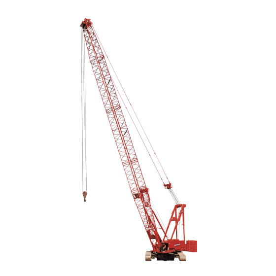
Sign In
Upload
Manuals
Brands
Manitowoc Manuals
Construction Equipment
2250
Manitowoc 2250 Manuals
Manuals and User Guides for Manitowoc 2250. We have
5
Manitowoc 2250 manuals available for free PDF download: Service And Maintenance Manual, Service Maintenance Manual, Operator's Manual
Manitowoc 2250 Service And Maintenance Manual (410 pages)
Brand:
Manitowoc
| Category:
Construction Equipment
| Size: 37.94 MB
Table of Contents
Table of Contents
5
Section 1
17
Continuous Innovation
17
Safety Messages
17
General
17
Safety Alert Symbol
17
Signal Words
17
Safe Maintenance Practices
17
Maintenance Instructions
18
Safe Maintenance Practices
18
Environmental Protection
19
Identification and Location of Components
20
Past Production and Tier 3 Engine Components
36
Tier 4 Engine Components
38
Crane Description of Operation
40
General Operation
40
Hydraulic Components
41
Hydraulic Tank
41
Shutoff Valve
41
Suction Manifold
41
Return Manifolds
41
Hydraulic Pumps
41
Charge Pressure
42
Hydraulic Motors
42
Main Pressure Monitoring
43
Basic Operation
43
Accessory Systems
45
Pressurized Air Supply
47
Engine Controls
48
Drum Identification
48
EPIC® Programmable Controller (PC)
49
Digital Display
49
Rated Capacity Indicator/Limiter (RCL)
49
Crane Modes
49
Electrical Power to Operator's Cab
50
Pressure Senders and Speed Sensors
52
Limit Switches and Faults
52
Hydraulic Brake Systems
52
Load Drum Air Brakes
53
Working (Service) Brakes
54
Load Drum Clutch Release System
54
Drum Pawls
55
Swing System Operation
56
General
56
Swing Brake and Swing Holding Brake
56
Swing Lock (Past Production)
56
Swing Right or Left
56
Travel System Operation
58
General
58
Travel Brakes
58
Two-Speed Travel Operation
58
Travel Detent Selector
58
Travel Forward and Reverse
58
Boom Hoist/Luffing Jib System Operation
61
General
61
Brake and Pawl
61
Boom Hoist/Luffing Jib Raise
61
Boom Hoist/Luffing Jib Lower
62
Load Drum System - Full Power
64
General
64
Drum Brake
64
Load Drum Hoisting
64
Load Drum Lowering
66
Dual Load Drum Motor Operation
66
Load Drum System - Free Fall
69
General
69
Load Drum Hoisting - Free Fall
69
Load Drum Lowering - Free Fall
69
Upper Accessory System Components
72
General
72
Jacking Cylinders
72
Adapter Frame Pin Cylinders
76
Gantry Cylinders
78
Lower Accessory System Components
80
General
80
Boom Hinge Pins
80
Boom Butt Handling Cylinder
82
Rigging Winch
84
Crawler Frame Pins
85
Air System Components
87
Counterweight/Back Hitch Pins
87
Hydraulic Quick Disconnect
88
General
88
MAX-ER™ 2000 Description of Operation
91
MAX-ER Components
91
MAX-ER Hydraulic Attachments
91
Auxiliary Pump
91
MAX-ER Accessory Valve
92
MAX-ER Pressurized Air Supply
92
EPIC® Programmable Controller
94
MAX-ER Modes
95
Electrical System
95
MAX-ER Remote Switch Assembly
95
Mast Back Hitch Pins Remote Switch
95
Digital Display
95
Pressure Senders and Speed Senders
95
Limit Switches
96
Back Hitch Pins
97
Back Hitch Pins Extend/Retract
97
Tongue Cylinder
98
Tongue Cylinder Extend
98
Tongue Cylinder Retract
99
Counterweight Jack Cylinders
100
Jack Cylinder(S) Extend
100
Jack Cylinder(S) Retract
101
Steering Pin Cylinders
103
Steering Pin Cylinders Disengage
103
Steering Pin Cylinders Engage
103
Steering Arm Cylinders
105
Steering Cylinders Extend (Swing/Crab)
105
Steering Cylinders Retract (Straight)
106
Counterweight Strap Cylinders
108
Counterweight Switch
110
Counterweight Strap Cylinders Lower
110
Counterweight Strap Cylinders Raise
110
Mast Stop Raising and Boom Stop
111
Mast Stop Raising Cylinders
111
Boom Stop Cushion Cylinders
111
Mast Stop
112
Mast Stop Cylinders
112
Mast Stop System Operation
112
Jib Stop Cylinders
113
Jib Stop System Operation
113
Drum 9 Operation
114
Drum 9 Brake
115
Drum 9 Hoisting (MAX-ER Mode)
115
Drum 9 Lowering (MAX-ER Mode)
117
Hydraulic Cooler Fan Drive - Tier 4 Only
119
Description
119
Maintenance
119
Hydraulic Schematics
125
Hydraulic System - General
125
Checking and Replacing Hydraulic Hoses
125
Hydraulic System Maintenance
126
Safety
126
Storing and Handling Oil
126
Storing and Handling Parts
126
Inspecting System
126
Servicing Pumps
127
Cleaning Fill Cap Assembly
127
Replacing Suction Filter Element
128
Changing Oil
129
Tightening Hydraulic Connections
131
General
131
Pipe Thread Connection
131
SAE Straight Thread Connection
131
ORS Connection
132
Split Flange Connection
132
SAE Flare Connection
133
Programmable Controller Calibration Procedures - Past
134
General
134
Controls Calibration
134
Pressure Sender Calibration
134
Programmable Controller Calibration Procedures - Current
134
Pressure Sender Calibration
135
Controls Calibration
135
Pressure Sender Replacement
136
General
136
Disc Brake Operational Test
138
General
138
Operational Test
138
Shop Procedure
140
General
140
Pump Identification
140
Pump Port Identification
140
Pump Components
140
Initial Oil Fill
141
Pressure Sender Calibration
141
Initial Start-Up
142
Controls Calibration
143
Fan and Pilot Pressure Adjustment
143
Charge Pressure Checks
143
Operating Pressure Checks
144
Boom Hoist down
144
Boom Hoist up
144
Swing
144
Auxiliary System Pressure Checks
145
Travel
145
Load Drums
145
Auxiliary System Relief Valve
145
Rotating Bed Jacking Cylinders
146
Connecting Pin Cylinders (Crawler, Boom Hinge, and Adapter Frame)
147
Boom Butt Handling Cylinder
147
Gantry Cylinders
147
System Speed Checks
148
Travel Straightness
148
Unloader Pilot Valve Maintenance
149
General
149
Adjustment
149
Maintenance
149
Moisture Ejector Valve Maintenance
150
General
150
Control Handle Positions
150
Operational Checks
150
Maintenance
150
Automatic Operation
150
Shut-Off
150
Air System Filter Maintenance
151
General
151
Daily Maintenance
151
Monthly Maintenance
151
Automatic Drain Valve Operation
152
Air System De-Icer Maintenance
152
Operation
152
Adjusting
152
Maintenance
153
Filling
153
Air Dryer Maintenance (Current Production)
155
Description
155
Operation and Leak Test
155
Disassembly
155
Cleaning and Inspection
156
Advertisement
Manitowoc 2250 Service Maintenance Manual (370 pages)
Brand:
Manitowoc
| Category:
Construction Equipment
| Size: 37.49 MB
Table of Contents
See End of this Manual for Alphabetical Index
5
Table of Contents
5
Section 1
17
Continuous Innovation
17
Safety Messages
17
General
17
Safety Alert Symbol
17
Signal Words
17
Safe Maintenance Practices
17
Maintenance Instructions
18
Safe Maintenance Practices
18
Environmental Protection
20
Identification and Location of Components
21
Tier 4 Final Engine Components
34
Crane Description of Operation
37
General Operation
37
Hydraulic Components
38
Hydraulic Pumps
38
Hydraulic Tank
38
Return Manifolds
38
Shut-Off Valve
38
Suction Manifold
38
Charge Pressure
39
Hydraulic Motors
39
Basic Operation
40
Monitoring the Main Pressure
40
Accessory Systems
43
Pressurized Air Supply
44
Drum Identification
45
Engine Controls
45
Crane Modes
46
Digital Display
46
EPIC® Programmable Controller (PC)
46
Rated Capacity Indicator/Limiter (RCI/RCL)
46
Electrical Power to Operator's Cab
47
Hydraulic Brake Systems
49
Limit Switches and Faults
49
Pressure Senders and Speed Sensors
49
Load Drum Air Brakes
50
Load Drum Clutch Release System
51
Working (Service) Brakes
51
Drum Pawls
52
General
52
Swing Brake and Swing Holding Brake
52
Swing Right or Left
52
Swing System Operation
52
General
54
Travel Brakes
54
Travel Detent Selector
54
Travel Forward and Reverse
54
Travel System Operation
54
Two-Speed Travel Operation
54
Boom Hoist/Luffing Jib System Operation
57
Brake and Pawl
57
General
57
Raising the Boom Hoist/Luffing Jib
57
Lowering the Boom Hoist/Luffing Jib
58
Drum Brake
60
General
60
Hoisting the Load Drum
60
Load Drum System-Full Power
60
Lowering the Load Drum
62
Dual Load Drum Motor Operation
63
General
66
Hoisting the Load Drum-Free Fall
66
Load Drum System-Free Fall
66
Lowering the Load Drum -Free Fall
66
General
69
Jacking Cylinders
69
Upper Accessory System Components
69
Adapter Frame Pin Cylinders
73
Gantry Cylinders
75
Boom Hinge Pins
77
General
77
Lower Accessory System Components
77
Boom Butt Handling Cylinder
79
Rigging Winch
81
Crawler Frame Pins
82
Air System Components
84
Counterweight/Backhitch Pins
84
General
85
Hydraulic Quick Disconnect
85
MAX-ER® 2000 Description of Operation
87
Auxiliary Pump
87
MAX-ER Components
87
MAX-ER Hydraulic Attachments
87
MAX-ER Accessory Valve
88
MAX-ER Pressurized Air Supply
88
EPIC® Programmable Controller
90
Digital Display
91
Electrical System
91
Mast Backhitch Pins Remote Switch
91
MAX-ER Modes
91
MAX-ER Remote Switch Assembly
91
Limit Switches
92
Pressure Senders and Speed Senders
92
Backhitch Pins
94
Backhitch Pins Extend/Retract
94
Tongue Cylinder
95
Tongue Cylinder Extend
95
Tongue Cylinder Retract
96
Counterweight Jack Cylinders
97
Jack Cylinder(S) Extend
97
Jack Cylinder(S) Retract
98
Steering Pin Cylinders
100
Steering Pin Cylinders Disengage
100
Steering Pin Cylinders Engage
101
Steering Arm Cylinders
102
Steering Cylinders Extend (Swing/Crab)
102
Steering Cylinders Retract (Straight)
103
Counterweight Strap Cylinders
104
Counterweight Strap Cylinders Lower
106
Counterweight Strap Cylinders Raise
106
Counterweight Switch
106
Boom Stop Cushion Cylinders
107
Mast Stop Raising and Boom Stop
107
Mast Stop Raising Cylinders
107
Mast Stop
108
Mast Stop Cylinders
108
Mast Stop System Operation
108
Jib Stop System Operation
109
Luffing Jib Stop Cylinders
109
Drum 9 Operation
110
Drum 9 Brake
111
Drum 9 Hoisting (MAX-ER Mode)
111
Drum 9 Lowering (MAX-ER Mode)
113
Hydraulic Cooler Fan Drive
114
Description
114
Maintenance
114
Section 2 Hydraulic and Air Systems
115
Checking and Replacing Hydraulic Hoses
119
Hydraulic Schematics
119
Hydraulic System-General
119
Hydraulic System Maintenance
120
Safety
120
Storing and Handling Oil
120
Inspecting the System
120
Storing and Handling Parts
120
Cleaning the Fill Cap Assembly
121
Servicing the Pumps
121
Replacing the Suction Filter Element
122
Changing the Oil
123
Tightening the Hydraulic Connections
125
General
125
Pipe Thread Connection
125
SAE Straight Thread Connection
125
ORS® Connection
126
Split Flange Connection
126
SAE Flare Connection
127
Programmable Controller Calibration Procedures
128
General
128
Calibrating the Pressure Sender
128
Calibrating the Controls
129
Replacing a Pressure Sender
130
General
130
Disc Brake Operational Test
132
General
132
Operational Test
132
Shop Procedure
134
General
134
Pump Identification
134
Pump Port Identification
134
Initial Oil Fill
135
Pressure Sender Calibration
135
Initial Startup
136
Adjusting the Fan and Pilot Pressure
137
Calibrating the Controls
137
Checking the Operating Pressure
138
Boom Hoist down
138
Boom Hoist up
138
Checking the Charge Pressure
138
Checking the Auxiliary System Pressure
139
Auxiliary System Relief Valve
139
Load Drums
139
Swing
139
Travel
139
Boom Butt Handling Cylinder
141
Connecting Pin Cylinders (Crawler, Boom Hinge, and Adapter Frame)
141
Gantry Cylinders
141
Rotating Bed Jacking Cylinders
141
Checking the System Speed
142
Travel Straightness
142
Unloader Pilot Valve Maintenance
143
General
143
Adjustment
143
Maintenance
144
Moisture Ejector Valve Maintenance
144
General
144
Control Handle Positions
144
Operational Checks
144
Automatic Operation
144
Shut-Off
144
Air System Filter Maintenance
145
General
145
Daily Maintenance
145
Monthly Maintenance
145
Automatic Drain Valve Operation
146
Air System De-Icer Maintenance
146
Operation
146
Adjusting
147
Maintenance
147
Filling
147
Disassembly
147
Inspection
147
Reassembly
147
Air Dryer Maintenance
148
Description
148
Replacing the Desiccant Cartridge
148
Breather Vent Maintenance
150
Solenoid Valve Maintenance
150
Operation
150
Air Line Connection
150
Electrical Connection
150
Normally Closed
150
Maintenance
151
Disassembly
151
Reassembly
151
Troubleshooting
151
Quick Release Valve Maintenance
152
General
152
Adjustment
152
Maintenance
154
Air Pressure Safety Switches Maintenance
154
Adjustment Requirements
154
General
154
Operation
154
Adjustment
155
Shuttle Valve Maintenance
156
General
156
Maintenance
156
Operation
156
Type a Air Regulator Maintenance
157
Adjustment
157
Installation
157
Maintenance
158
Pressure-Reducing Valve Maintenance
158
Operation
158
Adjustments
159
Maintenance
159
Type S Relay Valve Maintenance
160
Balanced Position
160
General
160
Increasing Pressure
160
Operation
160
Decreasing Pressure
161
Maintenance
161
Manitowoc 2250 Operator's Manual (312 pages)
Brand:
Manitowoc
| Category:
Construction Equipment
| Size: 29.61 MB
Table of Contents
Table of Contents
5
Section 1
15
Crane Data
15
Crane/Attachment Identification
15
Tier 4F Engine
15
Change of Ownership Registration
15
Crane Orientation
15
Identification and Location of Components
16
Crane Components
16
Engine Components
18
Hydraulic Tank Components
20
Outline Dimensions
21
Standard Crane (Series 3 Counterweight Arrangement Shown)
21
35-Foot Elevated Cab
22
Crane Weights
23
English and Metric Conversions
26
Direct Conversion
26
Inverse Conversion
26
Manitowoc Cranes Dealer
27
Section 2
29
Continuous Innovation
31
Nameplates and Decals
31
Safety Messages
31
General
31
Safety Alert Symbol
31
Signal Words
31
Symbol Identification
31
Safety and Information Signs
33
Maintaining Signs
33
Ordering Signs
33
Crane Access Points
34
General
34
Getting on or off Crane
35
Operator Manual/Capacity Chart Storage
37
Storing Manuals
37
Safe Operating Practices
38
General
38
Read the Operator Manual
38
Operator Qualifications
38
Operator Conduct
38
Pre-Start Checks
39
Leaving the Operator's Cab
39
Handling the Load
40
Power Failure
40
Operating at Night or in Bad Weather
40
Size of Load
40
Attaching the Load
41
Lifting/Moving the Load
41
Multiple-Load-Line Operation
42
Holding the Load
43
Signals
44
Safety Devices
44
Operational Aids
45
Category 1 Operational Aids
45
Category 2 Operational Aids
45
Assembling, Disassembling, or Operating Crane Near Electric Power and Transmission Lines
47
Electrocution Hazard
47
Setup and Operation
47
Electrocution Hazard Devices
48
Electrical Contact
48
Refueling
49
Fire Extinguishers
49
Accidents
49
Safe Maintenance
49
Maintenance Instructions
49
Safe Maintenance Practices
49
Environmental Protection
51
Boom Disassembly Safety
52
General
52
Location
52
Pin Removal
54
Disassembly Precaution
54
Personnel Handling Policy
55
Pedestal/Barge-Mounted Cranes
57
Pedestal-Mounted Crane
57
Definition
57
Examples
57
Barge-Mounted Crane
58
Definition
58
Examples
58
Capacity Charts
59
Shock Loading
59
Operation on Barge
59
Definition
59
General
59
Definitions
59
Crane Inspection
60
Transporting Crane on Barge
60
Standard Hand Signals for Controlling Crane Operations
68
Symbol Identification
70
Front Window Operation
76
Closing Window
76
Opening Window for Ventilation
76
Opening Window for Emergency Exit
76
Controls Identification and Function
76
General
76
A-Engine Controls
80
A1-Engine Run/Stop/Run Key Switch
80
A2-Engine Start Switch
80
A3-Engine Lights
80
A4-Exhaust System Lights
80
A5-Diesel Particulate Filter (DPF) Switch
81
A6-Diesel Exhaust Fluid (DEF) Gauge and Light
81
B-Accessory Controls
82
A7-Emergency Stop Switch
82
A8-Engine Foot Throttle
82
A9-Engine Hand Throttle
82
A10-Pump Drive Disconnect Handle
82
A11-Battery Disconnect Switch
82
B1-Tinted Visor
82
B2-Defroster Fan
82
B3-Horn Switch
82
C-Indicators
83
B4-Dome Light Switch
83
B5-Air Conditioner Temperature Selector
83
B6-Air Conditioner/Heater Switch
83
B7-Air Conditioner/Heater Fan Switch
83
B8-Panel Lights Switch
83
B9-Windshield Washer Switch
83
B10-Front Windshield Wiper Switch
83
B11-Overhead Windshield Wiper Switch
83
B12-Engine Block Heater
83
C4-Digital Display
84
C5-Digital Display Selector Switch
84
C6-Operating Limit Alert
84
C7-System Fault Alert
84
C8-Rotation Indicators
84
C9-Wind Speed Indicator
84
C10-Engine Hour Meter
84
C11-Boom Angle Indicator
84
C12-Drum Direction Indicator
84
D-Gauges
85
D1-Hydraulic Tank Temperature Display
85
D2-Fuel Level Gauge
85
D3-Engine Water Temperature Gauge
85
D4-Engine Oil Pressure Gauge
85
E-Special Controls and Indicators
86
D5-Battery Voltage Gauge
86
D6-Air Pressure Gauge
86
E1-Drum 1 Free Fall Light
86
E2-Drum 2 Free Fall Light
86
E3-Drum 3 Free Fall Light
86
E4-Crane Mode Selector
86
Main Modes
86
Crane Setup
86
Luffing Jib Setup
87
Auxiliary Modes
87
E5-Limit Bypass Switch
88
E6-Drum Selector
88
E7-Load Drum Indicator Lights
89
E8-Seat Switch
89
E9-MAX-ER Controls
89
E10-Aircraft Warning Beacon (Optional)
89
E11-Dome Light (Optional)
89
E12-Dome Light Dimmer Control (Optional)
89
E13-Clam Closing Control and Air Pressure Gauge
89
E14-APU Cab Key Switch (Optional)
89
Drum Identification
90
Handle-To-Drum Identification
91
F-Boom/Luffing Hoist Controls
92
G-Load Drum Controls
92
F1-Boom Hoist Handle
92
F2-Drum 4 Park Switch
92
F3-Drum 5 Park Switch
92
Full Power Mode (Either Load Drum)
92
Free Fall Mode (Either Load Drum)
92
G1-Left Handle
93
G2-Right Handle
93
G3-Drum 1 Park Switch
93
G4-Drum 2 Park Switch
93
G5-Drum 3 Park Switch
93
G6-Left Working Brake Pedal
93
G7-Right Working Brake Pedal
93
H-Swing Controls
94
J-Travel Controls
94
G8-Drum 9 Park Switch
94
G9-Auxiliary Drum 5 Handle (Optional)
94
H1-Swing Handle
94
H2-Swing Holding Brake Switch
94
H3-Swing Brake Switch
94
J1-Left Crawler Handle
94
J2-Right Crawler Handle
94
J3-Travel Detent Selector
94
Limit Devices
95
Boom up Limit
95
J4-Travel Park Switch
95
J5-Travel Speed Selector
95
Boom up Limit Bypass Test
95
Boom down Limit (if Equipped)
96
Block-Up Limit
96
Luffing Jib up Limits
96
Luffing Jib down Limits
97
Maximum Bail Limit
97
Minimum Bail Limit
97
Load Indicator
98
Mast up Limit
98
Seat Controls
98
Preparing Crane for Operation
99
Operation
99
Engine Startup
99
Boom/Luffing Hoist Operation
101
Swing Operation
102
Load Drum Operation
103
Liftcrane Operation-Full Power
103
Liftcrane Operation-Free Fall
104
Clamshell Operation-Standard
105
Selecting Clamshell Mode
105
Closing Bucket (Digging)
105
Hoisting Bucket
105
Advertisement
Manitowoc 2250 Operator's Manual (288 pages)
Brand:
Manitowoc
| Category:
Construction Equipment
| Size: 15.9 MB
Table of Contents
Manitowoc Toc-I
5
Table of Contents
5
Crane Data
9
Crane/Attachment Identification
9
Change of Ownership Registration
9
Crane Orientation
9
Identification and Location of Components
10
Current Tier 3 Production
12
Current Tier 4 Production
13
Outline Dimensions
14
Standard Crane (Series 3 Counterweight Arrangement Shown)
14
Foot Elevated Cab
15
Crane Weights
16
English and Metric Conversions
19
Direct Conversion
19
Inverse Conversion
19
Manitowoc Dealer
20
Section 2 Safety Information
21
Continuous Innovation
23
Nameplates and Decals
23
Safety Messages
23
General
23
Safety Alert Symbol
23
Signal Words
23
Symbol Identification
23
Safety and Information Signs
25
Maintaining Signs
25
Ordering Signs
25
Crane Access Points
26
Getting on or off Crane
26
General
26
Operator's Manual/Capacity Chart Storage
29
Storing Manuals
29
Safe Operating Practices
30
General
30
Operator Conduct
30
Operator Qualifications
30
Read Operator's Manual
30
Attaching Load
32
Handling Load
32
Size of Load
32
Lifting/Moving Load
33
Multiple Load Line Operation
34
Signals
35
Holding Load
35
Operational Aids
36
Category 1 Operational Aids
36
Category 2 Operational Aids
37
Safety Devices
36
Assembling, Disassembling, or Operating Crane Near Electric Power and Transmission Lines
38
Electrocution Hazard
38
Set-Up and Operation
38
Electrical Contact
39
Electrocution Hazard Devices
39
Accidents
40
Fire Extinguishers
40
Refueling
40
Safe Maintenance
40
Maintenance Instructions
40
Safe Maintenance Practices
40
Environmental Protection
42
Boom Disassembly Safety
43
General
43
Location
43
Disassembly Precaution
45
Pin Removal
45
Personnel Handling Policy
46
Pedestal/Barge Mounted Cranes
48
Pedestal Mounted Crane
48
Definition
48
Examples
48
Barge Mounted Crane
49
Definition
49
Examples
49
Capacity Charts
50
Shock Loading
50
Definition
50
Operation on Barge
50
Definitions
50
General
50
Crane Inspection
51
Transporting Crane on Barge
51
Section 3 Operating Controls and Procedures
53
Standard Hand Signals for Controlling Crane Operations
59
Symbol Identification
61
Controls Identification and Function
67
Closing Window
67
General
67
Opening Window for Emergency Exit
67
Opening Window for Ventilation
67
A - Engine Diagnostics
69
A1. Engine Stop Light
69
A2. Engine Warning Light
69
B - Engine Controls
69
B1. Engine Run/Stop/Run Key Switch
69
B2. Engine Start Switch
69
B3. Emergency Engine Stop Switch
70
B4. Engine Foot Throttle
70
B5. Engine Hand Throttle
70
B6. Pump Drive Disconnect Handle
70
B7. Battery Disconnect Switch
70
B8. DPF Switch (Tier 4 Only)
70
C - Accessory Controls
71
C1. Tinted Visor
71
C2. Defroster Fan
71
C3. Horn Switch
71
C4. Dome Light Switch
71
C5. Air Conditioner Temperature Selector
71
C6. Air Conditioner/Heater Switch
71
C7. Heater/Air Conditioner Fan Switch
71
C8. Panel Lights Switch
71
C9. Windshield Washer Switch
71
D - Indicators
72
D1. Mirrors
72
D2. Load Indicator Console
72
D3. Crane Level Display
72
D4. Digital Display and Selector Switch
72
D5. Operating Limit Alert
72
D6. System Fault Alert
72
D7. Rotation Indicators
72
D8. Wind Speed Indicator
72
D9. Engine Hourmeter
72
D11 - High Exhaust System Temperature (Tier 4)
73
D12 - DPF on (Tier 4)
73
D13 - DPF Regeneration Inhibit (Tier 4)
73
E - Gauges
73
E1. Hydraulic Tank Temperature Display
73
E2. Fuel Level Gauge
73
E3. Engine Water Temperature Gauge
73
E4. Engine Oil Pressure Gauge
73
E5. Battery Voltage Gauge
73
E6. Air Pressure Gauge
73
F4. Crane Mode Selector
75
F10. Not Used
79
F11. MAX-ER Controls
79
F12. Aircraft Beacon Warning Light - (Optional)
79
F13. Dome Light - (Optional)
79
F14. Dome Light Dimmer Control - (Optional)
79
F5. Limit Bypass Switch
79
F6. Luffing Jib Limit Bypass Switch
79
F7. Drum Selector
79
F8. Load Drum Indicator Lights
79
F9. Seat Switch
79
Drum Identification
80
Handle-To-Drum Identification
81
Free-Fall Mode (Either Load Drum)
82
Full-Power Mode (Either Load Drum)
82
G - Boom/Luffing Hoist Controls
82
G1. Boom/Luffing Hoist Handle
82
G2. Drum 4 Park Switch
82
G3. Drum 5 Park Switch
82
H - Load Drum Controls
82
H1. Left Handle
83
H2. Right Handle
83
H3. Drum 1 Park Switch
83
H4. Drum 2 Park Switch
83
H5. Drum 3 Park Switch
83
H6. Left Working Brake Pedal
83
H7. Right Working Brake Pedal
83
H8. Drum 9 Park Switch
84
H9. Auxiliary Drum 5 Handle (Optional)
84
J - Swing Controls
84
J1. Swing Handle
84
J2. Swing Holding Brake Switch
84
J3. Swing Brake Switch
84
J4. Swing Lock Switch
84
K - Travel Controls
84
K1. Left Crawler Handle
85
K2. Right Crawler Handle
85
K3. Travel Detent Selector
85
K4. Travel Park Switch
85
K5. Travel Speed Selector
85
Front Window Operation
67
Boom down Limit (if Equipped)
86
Block-Up Limit
86
Limit Devices
86
Boom up Limit
86
Luffing Jib up Limit
86
Luffing Jib down Limits
87
Luffing Jib Max down Limit
87
Maximum Bail Limit
87
Minimum Bail Limit
87
Load Indicator
88
Mast up Limit
88
Seat Controls
89
Preparing Crane for Operation
90
Operation
91
Engine Start-Up
91
Boom/Luffing Hoist Operation
93
Swing Operation
94
Liftcrane Operation - Full-Power
95
Load Drum Operation
95
Clamshell Operation - Standard
97
Closing Bucket (Digging)
97
Dumping Bucket
97
Hoisting Bucket
97
Lowering Bucket
97
Selecting Clamshell Mode
97
Travel Operation
98
Stopping Engine / Leaving Crane Unattended
100
Special Controls
102
Electric Drive
102
General
102
Electric Drive Start-Up
105
Shut down / Unattended Crane with Electric Drive
107
Auxiliary Engine - Cummins QSX15 Engine
108
Auxiliary Engine Controls
108
Auxiliary Engine Shut down
108
Auxiliary Engine Start-Up
108
General Engine Information
108
Auxiliary Engine Junction Box
109
Clamshell Operation - Manually Operated Clutch
110
General
110
Automatic Clutch Control
111
Closing Bucket (Digging)
111
Manual Clutch Control
111
Manual and Automatic Clutch Control
112
Clamshell Operation with Independent Drums
113
General
113
Operating Options
113
Digging
114
Drum 5 Operation (Boom Hoist Diverted)
114
Drum 5 Operation (Travel Diverted)
114
General
114
Load Drum Operation
114
Luffing Hoist Operation
114
Synchronized Control Options
114
Load Drum Operation
115
Luffing Hoist Operation
115
Remote Controls
117
General
117
Controls Identification and Operation
117
Engine Run/Stop Switch
117
Engine Speed Switch
117
Engine Start Switch
117
Hydraulic Disconnect Switch (Rotating Frame Quick-Disconnect)
117
Power Switch
118
Programmable Controller Calibration Procedures
120
Digital Display Readings
121
Diagnostic Display
129
Engine Diagnostics (Cummins QSX15 Engine)
136
Drum Interlock
137
Removing Drum Interlock
138
Swing Limiter Operation
140
Adjustment
140
General
140
Programming Swing Limits
140
Swing Limit Switch Adjustment
143
Swing Speed/Torque Adjustment
140
Swing Drive Disconnect Operation
145
Connecting Crane Swing Drive
145
Disconnecting Crane Swing Drive
145
General
145
Pile Driving System Controls
146
Components Function
146
Cylinder Operating Controls
146
Directional Control Valve
146
General
146
Hydraulic Filter
146
Hydraulic Pump
146
Hydraulic Tank
146
Spotter System Dump Valve
146
Wind Conditions
149
General
149
Cold Weather Heater Package
150
General
150
Heaters
150
Thermostats
150
Turning Heaters off
150
Turning Heaters on
150
Preparation for Cold Weather
153
Battery
153
Cold Weather Starting Aid
153
Coolant and Oil Pan Heaters
153
Cooling System
153
Crane Limitations
153
Engine Oil
153
Fuel Oil
153
Gear Oil
153
Wire Rope
153
Circuit Breakers
154
Air System
154
General
154
Hydraulic Oil
154
Manitowoc 2250 Operator's Manual (172 pages)
Luffing Jib
Brand:
Manitowoc
| Category:
Construction Equipment
| Size: 11.15 MB
Table of Contents
Table of Contents
5
Section 1
9
Crane Data
11
Crane/Attachment Identification
11
Change of Ownership Registration
11
Manitowoc Dealer
11
Crane Orientation
11
Identification of Luffing Jib Components
11
Crane Weights
13
English and Metric Conversions
16
Direct Conversion
16
Inverse Conversion
16
Table of Contents
21
Section 2
21
Continuous Innovation
21
Nameplates and Decals
21
Safety Messages
21
General
21
Safety Alert Symbol
21
Signal Words
21
Symbol Identification
21
Safety and Information Signs
23
Maintaining Signs
23
Ordering Signs
23
Crane Access Points
24
General
24
Getting on or off Crane
24
Operator's Manual/Capacity Chart Storage
27
Storing Manuals
27
Safe Operating Practices
28
General
28
Read Operator's Manual
28
Operator Qualifications
28
Operator Conduct
28
Handling Load
30
Size of Load
30
Attaching Load
30
Lifting/Moving Load
31
Multiple Load Line Operation
32
Signals
33
Holding Load
33
Safety Devices
34
Operational Aids
34
Category 1 Operational Aids
34
Category 2 Operational Aids
35
Assembling, Disassembling, or Operating Crane Near Electric Power and Transmission Lines
36
Electrocution Hazard
36
Set-Up and Operation
36
Electrocution Hazard Devices
37
Electrical Contact
37
Refueling
38
Fire Extinguishers
38
Accidents
38
Safe Maintenance
38
Maintenance Instructions
38
Safe Maintenance Practices
38
Environmental Protection
40
Boom Disassembly Safety
41
General
41
Location
41
Pin Removal
43
Disassembly Precaution
43
Personnel Handling Policy
44
Pedestal/Barge Mounted Cranes
46
Pedestal Mounted Crane
46
Definition
46
Examples
46
Barge Mounted Crane
47
Definition
47
Examples
47
Capacity Charts
48
Shock Loading
48
Operation on Barge
48
Definition
48
General
48
Definitions
48
Crane Inspection
49
Transporting Crane on Barge
49
Section 3
51
Standard Hand Signals for Controlling Crane Operations
53
General Operation
55
Luffing Jib Operating Controls
55
Crane Mode Selector
55
Digital Display
55
Limit Bypass Switches
55
Automatic Jib Stop
55
Past Production Jib Stops
55
Boom/Luffing Hoist Control
56
Selecting Desired Hoist
56
Boom Hoist
56
Luffing Hoist
56
Operating Precautions
56
Current Production Jib Stops
56
Wind Conditions
57
Advertisement
Related Products
Manitowoc 2000
Manitowoc 2250 MAX-ER 2000
Manitowoc 2253000
Manitowoc Lincoln 2500 Series
Manitowoc Lincoln 2501-001
Manitowoc Lincoln 2502-000
Manitowoc Lincoln 2502-001
Manitowoc Lincoln 2504-001
Manitowoc Lincoln 2505-000
Manitowoc Lincoln 2507-000
Manitowoc Categories
Construction Equipment
Ice Maker
Accessories
Dispenser
Kitchen Appliances
More Manitowoc Manuals
Login
Sign In
OR
Sign in with Facebook
Sign in with Google
Upload manual
Upload from disk
Upload from URL