Manitowoc 2250 Service And Maintenance Manual
Hide thumbs
Also See for 2250:
- Service maintenance manual (370 pages) ,
- Operator's manual (312 pages) ,
- Operator's manual (288 pages)
Table of Contents
Advertisement
Advertisement
Chapters
Table of Contents
Troubleshooting

Related Manuals for Manitowoc 2250


Summary of Contents for Manitowoc 2250
- Page 1 Manitowoc 2250 Service/Maintenance Manual...
- Page 3 The serial number of the crane and applicable attachments (Luffing Jib, MAX-ER ) is the only method your Manitowoc dealer or the Manitowoc Crane Care Lattice Team has of providing you with correct parts and service information. The serial number is located on a crane identification plate attached to the operator’s cab and each attachment.
- Page 4 THE ORIGINAL LANGUAGE OF THIS PUBLICATION IS ENGLISH...
-
Page 5: Table Of Contents
2250 SERVICE/MAINTENANCE MANUAL TABLE OF CONTENTS See end of this manual for Alphabetical Index SECTION 1 ..........Introduction Continuous Innovation. - Page 6 TABLE OF CONTENTS 2250 SERVICE/MAINTENANCE MANUAL Storing and Handling Oil ............2-2 Storing and Handling Parts .
- Page 7 Model 2250 MAX-ER 2000™ Test Voltages ........
- Page 8 TABLE OF CONTENTS 2250 SERVICE/MAINTENANCE MANUAL MAX-ER Controller Pin Identification ..........3-32 MAX-ER Controller Wire Identification .
- Page 9 2250 SERVICE/MAINTENANCE MANUAL TABLE OF CONTENTS Removing Straps from Service............4-18 Inspection Checklist .
- Page 10 TABLE OF CONTENTS 2250 SERVICE/MAINTENANCE MANUAL Sheave, Roller, And Drum Inspection ........... 5-30 Load Block and Hook-And-Weight Ball Inspection.
- Page 11 2250 SERVICE/MAINTENANCE MANUAL TABLE OF CONTENTS General............... . 7-25 Regeneration .
- Page 12 TABLE OF CONTENTS 2250 SERVICE/MAINTENANCE MANUAL Test 23 — Servicing the Motor Loop Flushing (Purge) Valves ......10-58 Test 24 —...
- Page 13 Travel Forward and Reverse ........1-42 Manitowoc...
- Page 14 2250 SERVICE/MAINTENANCE MANUAL Boom Hoist/Luffing Jib System Operation ....... 1-45 General .
- Page 15 2250 SERVICE/MAINTENANCE MANUAL Steering Cylinders Retract (Straight) ....... 1-90 Counterweight Strap Cylinders ........1-92 Counterweight Switch .
- Page 16 2250 SERVICE/MAINTENANCE MANUAL THIS PAGE INTENTIONALLY LEFT BLANK 1-iv Published 11-06-15, Control # 040-13...
-
Page 17: Section 1
Due to continuing product innovation, the information in this manual is subject to change without notice. If you are in CAUTION doubt about any procedure, contact your Manitowoc dealer Without the safety alert symbol, identifies potential or the Manitowoc Crane Care Lattice Team. -
Page 18: Maintenance Instructions
INTRODUCTION 2250 SERVICE/MAINTENANCE MANUAL Maintenance Instructions To ensure safe and proper operation of Manitowoc cranes, they must be maintained according to the instructions WARNING contained in this manual and the Operator Manual provided Burn and Inhalation Hazards! with the crane. -
Page 19: Environmental Protection
13. Read safety information in battery manufacturer’s 28. Unless authorized in writing by Manitowoc, do not alter instructions before attempting to charge a battery. the crane in any way that affects crane’s performance (to include welding, cutting, or burning of structural 14. -
Page 20: Identification And Location Of Components
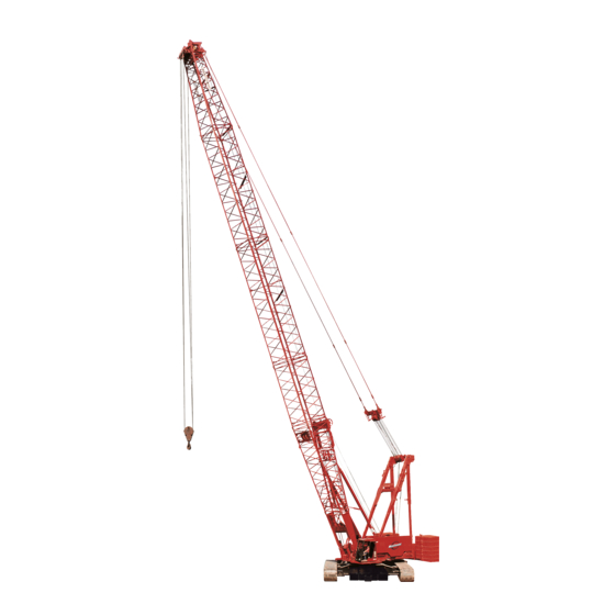
INTRODUCTION 2250 SERVICE/MAINTENANCE MANUAL IDENTIFICATION AND LOCATION OF COMPONENTS P891 P889 P887 Item Description #44 Heavy Lift Boom P892 Physical Air Cushioned Boom Stop Gantry Gantry Backhitch (telescopic) Boom Stop Limit Switch Rotating Bed Upper Counterweight Crawler Output Planetary with Drive Tumbler Crawler Operator’s Cab... - Page 21 2250 SERVICE/MAINTENANCE MANUAL INTRODUCTION THIS PAGE INTENTIONALLY LEFT BLANK Manitowoc Published 11-06-15, Control # 040-13...
- Page 22 INTRODUCTION 2250 SERVICE/MAINTENANCE MANUAL See View B P894 P895 See View A P896 P897 See View A See View B A468 P898 See View B See View C P899 FIGURE 1-2 Published 11-06-15, Control # 040-13...
- Page 23 2250 SERVICE/MAINTENANCE MANUAL INTRODUCTION Item Description Crawler Drive Motor Travel Brake (disc) Crawler Connecting Pin Cylinder (hydraulic) Boom Hoist Boom Hoist Motor Boom Hoist Brake (disc) Boom Hoist Planetary Crawler Input Planetary Crawler Drive Shaft P890 View A Rear Load Drum...
- Page 24 INTRODUCTION 2250 SERVICE/MAINTENANCE MANUAL P888 P902 P903 See View D See View F See View E A468 P601 P905 P904 FIGURE 1-3 Published 11-06-15, Control # 040-13...
- Page 25 2250 SERVICE/MAINTENANCE MANUAL INTRODUCTION P906 A470 View E Typical Four Places P907 View D Typical Outboard End of View F Each Drum Shaft Item Description Hydraulic Tank Hydraulic Tank Filters (under grate in tank) Hydraulic Tank Vacuum and Temperature Senders...
- Page 26 INTRODUCTION 2250 SERVICE/MAINTENANCE MANUAL See Operating Control topic in Section 3 of the Crane Operator Manual for complete list of operating controls P908 P909 P911 A1060 Behind Seat Under Right Console A974 P910 FIGURE 1-4 1-10 Published 11-06-15, Control # 040-13...
- Page 27 2250 SERVICE/MAINTENANCE MANUAL INTRODUCTION P912 Under Operator’s Cab Item‘ Description Rated Capacity Indicator/Limiter Console Front Console Crane Mode (select and confirm) Digital Display Cab Power Switch Brake Treadle Valve Right Console Load Drum Controller Handle Center Switch Foot Throttle Pedal...
- Page 28 INTRODUCTION 2250 SERVICE/MAINTENANCE MANUAL P913 P914 P915 38 (Tier 3 and Past Production) A1064 P916 P913 FIGURE 1-5 1-12 Published 11-06-15, Control # 040-13...
- Page 29 2250 SERVICE/MAINTENANCE MANUAL INTRODUCTION Item Description Front Drum Clutch Solenoid Valve Front Drum Parking Brake Solenoid Valve Rear or Right Rear Drum Clutch Solenoid Valve Rear or Right Rear Drum Parking Brake Solenoid Valve Left Rear Drum Clutch Solenoid Valve...
- Page 30 INTRODUCTION 2250 SERVICE/MAINTENANCE MANUAL P917 P918 P919 Past Production and Tier 3 P920 See Page P921 1-16 P923 FIGURE 1-6 P922 1-14 Published 11-06-15, Control # 040-13...
- Page 31 2250 SERVICE/MAINTENANCE MANUAL INTRODUCTION Item Description MAX-ER Hydraulic Quick-Couplers MAX-ER Electric Receptacle MAX-ER Load Sensing Storage Receptacle Auxiliary Valves Junction Box Not Used Jacking Remote Control Receptacle Not Used Setup Remote Control Jacking Remote Control Engine Air Cleaner (Past production and Tier 3 shown)
- Page 32 INTRODUCTION 2250 SERVICE/MAINTENANCE MANUAL A1088 Spares 192115_3a End View End View Past Production Current Production Item Description Item Description Right Front Jack Retract Solenoid Valve Right Front Jack Retract Solenoid Valve Right Front Jack Extend Solenoid Valve Right Rear Jack Extend Solenoid Valve...
- Page 33 2250 SERVICE/MAINTENANCE MANUAL INTRODUCTION THIS PAGE INTENTIONALLY LEFT BLANK Manitowoc 1-17 Published 11-06-15, Control # 040-13...
- Page 34 INTRODUCTION 2250 SERVICE/MAINTENANCE MANUAL P926 Left Side Boom Hoist Drum P925 Under Rear of Rotating Bed Inside Carbody P924 Under Rear of Rotating Bed P929 A468 Inside Carbody P927 P928 Under Rear of Rotating Bed FIGURE 1-7 1-18 Published 11-06-15, Control # 040-13...
- Page 35 2250 SERVICE/MAINTENANCE MANUAL INTRODUCTION Item Description Boom Hoist Brake Solenoid Valve Return Oil Check Valve (3 places) Drum Brake Relay Valve (2 each drum brake) Drum Brake Lever Drum Brake Quick-Release Valve (2 each drum brake) Adapter Frame Connecting Pin Cylinder (4 places)
-
Page 36: Past Production And Tier 3 Engine Components
INTRODUCTION 2250 SERVICE/MAINTENANCE MANUAL PAST PRODUCTION AND TIER 3 ENGINE COMPONENTS P931 Under Rear of Rotating Bed P930 See View B See View C P932 A468 P933 View A A1088 See View F See View E See View D View C... - Page 37 2250 SERVICE/MAINTENANCE MANUAL INTRODUCTION P934 Item Description Diagnostic Gauge Coupler (typical each sender) Right Travel Pressure Sender Spares Boom Hoist Pressure Sender Load Drum System Pressure Sender Load Drum Charge Pressure Sender Swing Right “B” Pressure Sender Swing Left “A” Pressure Sender...
-
Page 38: Tier 4 Engine Components
INTRODUCTION 2250 SERVICE/MAINTENANCE MANUAL TIER 4 ENGINE COMPONENTS 112195-2 81017295_1 Under Rear of Rotating Bed P930 P932 See View B See View C A468 View from Top of Crane Above Engine See View D View A See View E DPF w/Exhaust_IMG_7151... - Page 39 2250 SERVICE/MAINTENANCE MANUAL INTRODUCTION Item Description Diagnostic Gauge Coupler (typical each sender) Right Travel Pressure Sender Spares Boom Hoist Pressure Sender Load Drum System Pressure Sender Load Drum Charge Pressure Sender Swing Right “B” Pressure Sender Swing Left “A” Pressure Sender...
-
Page 40: Crane Description Of Operation
Figure 1-10 for the following procedure. displayed on digital display screen in operator’s cab. This section describes the model 2250 powered with the A single diesel engine provides power to operate system Cummins QSX15 or the Caterpillar 3406C engine. Standard pumps through a pump drive transmission. -
Page 41: Hydraulic Components
2250 SERVICE/MAINTENANCE MANUAL INTRODUCTION Hydraulic Components displayed as a pressure between 7 and 18 psi (0.5 and 1.2 bar absolute) depending on engine speed, ambient See Hydraulic Schematic Drawing at the end of this section. temperature, and filter condition. The breather protects the... -
Page 42: Charge Pressure
INTRODUCTION 2250 SERVICE/MAINTENANCE MANUAL requirements for fan motors and pilot fluid pressure for Pump system multifunction valves control maximum system accessory valve operation. pressure and protect each pump system from damage by limiting pressure spikes in each operating direction. When... -
Page 43: Main Pressure Monitoring
2250 SERVICE/MAINTENANCE MANUAL INTRODUCTION Main Pressure Monitoring maintains spool in a neutral position until the 16 psi (1 bar) chamber spring pressure is reached. Each system digital display screens display the monitored In travel pumps, the pressure relief and pressure-limiting system pressure. - Page 44 INTRODUCTION 2250 SERVICE/MAINTENANCE MANUAL RF-03 PUMP MOTOR 340 PSI OUTPUT (23 bar) MAX. DISP. INPUT FIGURE 1-12 The pressure limiting relief valve (1) serves as pilot valve to system pressure of 4,930 psi (340 bar) is reached. When open system relief valve (5) when desired relief pressure system pressure exceeds the PCOR setting, the valve shifts setting is reached.
-
Page 45: Accessory Systems
2250 SERVICE/MAINTENANCE MANUAL INTRODUCTION Motor case fluid drainage lubricates the motor and provides Accessory system pressure builds up to 3,500 psi (241 bar) a re-circulation of hydraulic fluid to control heat in closed- allowing fluid to the auxiliary systems through auxiliary loop system. - Page 46 INTRODUCTION 2250 SERVICE/MAINTENANCE MANUAL RF-04 AUXILIARY PUMP FAN PUMP AUXILIARY SYSTEM DISABLE RELIEF VALVE HS-12 SUCTION MANIFOLD TO LOWER ACCESSORY VALVE PILOT PRESSURE UPPER ACCESSORY VALVE 2000 psi 300 psi (PAST PRODUCTION) (138 bar) (21 bar) FAN CIRCUIT WITH CATERPILLAR ENGINE...
-
Page 47: Pressurized Air Supply
2250 SERVICE/MAINTENANCE MANUAL INTRODUCTION Pressurized Air Supply Each air solenoid valve in this section is assigned an AS number. The AS number identifies each air solenoid valve. Figure 1-14 for the following procedure. AS-1 Back Hitch Pins Extend Pressurized air is provided to the crane's air cylinder systems —... -
Page 48: Engine Controls
INTRODUCTION 2250 SERVICE/MAINTENANCE MANUAL Engine Controls Three engine diagnostic lights are mounted on front console, see Engine Diagnostics in Section 10 for diagnostic light See the engine manufacturer’s manual for instructions. information. The engine is started and stopped with engine key switch. -
Page 49: Epic® Programmable Controller (Pc)
Digital Display The Model 2250 crane’s boom, load lines, swing, crawler Digital display screen on front console shows operating t r a c k s , a n d a c c e s s o r y c o m p o n e n ts a r e c o n t r o l l e d... -
Page 50: Electrical Power To Operator's Cab
INTRODUCTION 2250 SERVICE/MAINTENANCE MANUAL • In Clamshell mode, two load drums (holding and When the engine run/stop switch is placed in the run closing) are operated at the same time and controlled position, voltage is available at the key-operated engine start with one load drum control handle. - Page 51 2250 SERVICE/MAINTENANCE MANUAL INTRODUCTION RF-09 120 AMP 24 VDC 12 VDC STARTER MOTORS STARTER SOLENOIDS ETHER SYSTEM START HOUR METER IGNR FAN RELAY 8ECM MOTOR COOLANT 8 AMP LEVEL IGNITION IGNR RELAY ENGINE CONTROL MODULE 8 AMP ENGINE ETHER RELAY...
-
Page 52: Pressure Senders And Speed Sensors
INTRODUCTION 2250 SERVICE/MAINTENANCE MANUAL Pressure Senders and Speed Sensors required load holding pressure for load drums, boom hoist drum, or luffing hoist drum. Figure 1-18 for the following procedure. Drum speed sensors on drum shafts or flanges detect speed Pressure senders monitor drum system pressures, load and direction of drum movement. -
Page 53: Load Drum Air Brakes
2250 SERVICE/MAINTENANCE MANUAL INTRODUCTION RF-11 87FA REGULATED 10V DC OUT MAIN MAIN LOWER UPPER OPERATING LIMIT ALARM BLOCK UP LIMIT WB-06 WC-35 MAX. WORKING ANGLE LIMIT WB-17 LIGHT MAXIMUM ANGLE LIMIT WA-35 SYSTEM FAULT ALARM WB-16 MINIMUM ANGLE LIMIT WC-34 LIGHT HYDRAULIC FLUID TEMP. -
Page 54: Working (Service) Brakes
INTRODUCTION 2250 SERVICE/MAINTENANCE MANUAL WORKING BRAKE PEDAL NOT USED REGULATOR WORKING BRAKE RELAY BRAKE SOLENOID BRAKE RELAY AS7 (DRUM 1) AS9 (DRUM 2) AS11 (DRUM 3) QUICK QUICK RELEASE RELEASE VALVE BRAKE VALVE CYLINDERS 89V (DRUM 1) 89U (DRUM 2) -
Page 55: Drum Pawls
2250 SERVICE/MAINTENANCE MANUAL INTRODUCTION which clutches are released, depending on control handle If a pawl is engaged during hoisting up, a hoist operating command and mode selected. drive fault occurs when stopped because the PC cannot command down against pawl to prove the brake is applied. -
Page 56: Swing System Operation
INTRODUCTION 2250 SERVICE/MAINTENANCE MANUAL Swing System Operation HS-7. The brake solenoid valve shifts to close fluid flow to brake and opens tank port to apply the brake. NOTE: References to “swing lock” are for past production Swing holding brake switch is located on the side of swing cranes as the swing lock is disabled on current control handle. - Page 57 2250 SERVICE/MAINTENANCE MANUAL INTRODUCTION engine speed. The PC sends a 0 volt output to adjust swashplate to centered position. RF-13 WD-19 50 AMP CRANE DISPLAY WD-20 87FA 10 VDC REGULATED SUPPLY WA-01 LEFT RIGHT WC-24 SWING PUMP SWING CONTROL HANDLE...
-
Page 58: Travel System Operation
INTRODUCTION 2250 SERVICE/MAINTENANCE MANUAL Travel System Operation crawler brakes. If brake pressure or electrical power is lost when operating, brakes apply. General Two-Speed Travel Operation Figure 1-23 Figure 1-24 for the following procedure. Travel 2-speed switch allows operator to select low speed Each travel hydraulic pump drives one crawler system motor when smoother start is required. - Page 59 2250 SERVICE/MAINTENANCE MANUAL INTRODUCTION RF-15 WD-19 50 AMP 87FA 10 VDC REGULATED SUPPLY WA-01 CRANE DISPLAY WD-20 REVERSE FORWARD WC-23 LEFT TRAVEL PUMP LEFT TRAVEL CONTROL HANDLE WA-07 WC-15 RIGHT TRAVEL PUMP REVERSE FORWARD SWING/TRAVEL ALARM WD-35 RIGHT TRAVEL CONTROL HANDLE...
- Page 60 INTRODUCTION 2250 SERVICE/MAINTENANCE MANUAL RF-16 RIGHT TRAVEL PUMP FORWARD SHUTTLE VALVE RIGHT PRESSURE PILOT PRESSURE FROM SENDER 350 PSI BOOM HOIST CHARGE (24 BAR) PUMP AT 350 PSI (24 BAR) REVERSE SUCTION MANIFOLD LEFT TRAVEL PUMP FORWARD HS-1 HS-35 SHUTTLE...
-
Page 61: Boom Hoist/Luffing Jib System Operation
2250 SERVICE/MAINTENANCE MANUAL INTRODUCTION Boom Hoist/Luffing Jib System Operation Boom Hoist/Luffing Jib Raise The following description is for the boom hoist system. The General luffing jib system is similar. Figure 1-25, Figure 1-26, and Figure 1-27 for the When left side console control handle is moved back for following procedure. -
Page 62: Boom Hoist/Luffing Jib Lower
INTRODUCTION 2250 SERVICE/MAINTENANCE MANUAL RF-17 50 AMP WD-19 87FA 10 VDC REGULATED SUPPLY WA-01 CRANE DISPLAY WD-20 RAISE LOWER WC-14 BOOM HOIST PUMP LEFT SIDE CONTROL HANDLE WA-05 BOOM HOIST MOTOR WE-29 BOOM ANGLE WA-20 INDICATOR LUFFING JIB MOTOR WD-24 LUFF. - Page 63 2250 SERVICE/MAINTENANCE MANUAL INTRODUCTION The PCOR valve over-rides the command from servo PC flow. Pressure builds on fluid return side of closed-loop, valve, increasing motor displacement and output torque and acting as a hydraulic brake to control lowering speed. reducing output speed. When PCOR valve closes, control of When boom hoist control handle is moved toward neutral the motor returns to servo PC valve.
-
Page 64: Load Drum System - Full Power
INTRODUCTION 2250 SERVICE/MAINTENANCE MANUAL RF-19 BOOM HOIST BOOM HOIST (LUFFING JIB) (LUFFING JIB) PAWL IN PAWL OUT BOOM HOIST (LUFFING JIB) PAWL CYLINDER AS-14 AS-13 AS-16 (LUFFING JIB) AS-15 (LUFFING JIB) BOOM HOIST (LUFFING JIB) DRUM FLANGE MAIN AIR MANIFOLD FIGURE 1-27 Load Drum System —... - Page 65 2250 SERVICE/MAINTENANCE MANUAL INTRODUCTION solenoid AS-9. The valve is enabled and shifts to allow maximum displacement side of servo cylinder. The PCOR manifold air pressure to release spring applied brake. valve over-rides the command from servo PC valve, increasing motor displacement and output torque and Pump EDC continues to tilt swashplate in the up direction as reducing output speed.
-
Page 66: Load Drum Lowering
INTRODUCTION 2250 SERVICE/MAINTENANCE MANUAL When control handle is moved toward neutral position, the motor torque is not too high. The PC monitors motor PC compensates for hydraulic system leakage or changing displacement and controls motor speed by regulating the engine speed. The PC sends a 0 volt output to pump EDC hydraulic fluid flow through the pump. - Page 67 2250 SERVICE/MAINTENANCE MANUAL INTRODUCTION LOAD DRUM PUMP 2 LOAD DRUM PUMP 1 RF-20 PRESSURE SENDER .060 340 PSI 340 PSI (23 BAR) (23 BAR) DOWN DOWN SUCTION SUCTION MANIFOLD MANIFOLD CHARGE MANIFOLD 8 GPM PRESSURE (30 m/l) SENDER 200 PSI...
- Page 68 INTRODUCTION 2250 SERVICE/MAINTENANCE MANUAL RF-22 WORKING BRAKE PEDAL NOT USED REGULATOR WORKING BRAKE RELAY DRUM 1 BRAKE CYLINDERS BRAKE BRAKE SOLENOID AS9 (DRUM 2) RELAY DRUM 1 CLUTCH CYLINDER QUICK RELEASE VALVE QUICK DRUM 2 RELEASE BRAKE VALVE CYLINDERS 89V (DRUM 1)
-
Page 69: Load Drum System - Free Fall
2250 SERVICE/MAINTENANCE MANUAL INTRODUCTION Load Drum System — Free Fall The procedure for hoisting in Free Fall mode is the same as in Standard mode. The selected free fall drum clutch is General engaged and brake is released by the PC. See Load Drum Hoisting topic in previous section. - Page 70 INTRODUCTION 2250 SERVICE/MAINTENANCE MANUAL Begin applying load drum working brake pedal as selected control handle is moved to off to hold the load when the PC releases the clutch from drum shaft. The load will fall WARNING uncontrolled if working brake pedal is not applied before...
- Page 71 2250 SERVICE/MAINTENANCE MANUAL INTRODUCTION RF-24 WORKING BRAKE PEDAL NOT USED REGULATOR WORKING BRAKE RELAY BRAKE BRAKE SOLENOID AS9 (DRUM 2) RELAY DRUM 1 BRAKE CYLINDERS DRUM 1 CLUTCH CYLINDER QUICK RELEASE VALVE QUICK DRUM 2 RELEASE BRAKE VALVE CYLINDERS DRUM...
-
Page 72: Upper Accessory System Components
INTRODUCTION 2250 SERVICE/MAINTENANCE MANUAL Upper Accessory System Components General WARNING Upper accessory system components include four jacking Collapsing Hazard! cylinders, front and rear adapter frame pin cylinders, and gantry raising cylinders. During normal operation the upper Keep rotating bed as level as possible while jacking. - Page 73 2250 SERVICE/MAINTENANCE MANUAL INTRODUCTION Restraining section of counterbalance valves open, When power button or jacking switch is moved to off position, controlling fluid flow out of jacking cylinders. Fluid then exits the PC sends a 0 volt output to shift spool of solenoid valves counterbalance valves and flows out of upper accessory HS-25 and HS-27 to center position.
- Page 74 INTRODUCTION 2250 SERVICE/MAINTENANCE MANUAL Jacking Cylinders Retract valves. Fluid then enters rod end of front jacking cylinders, retracting the cylinders to lower the front of rotating bed. The following operating description is for front jacks. Fluid exhausting from piston end of jacking cylinders is...
- Page 75 2250 SERVICE/MAINTENANCE MANUAL INTRODUCTION RF-26 LEFT REAR JACK LEFT FRONT JACK RIGHT FRONT JACK RIGHT REAR JACK AUXILIARY PUMP FAN PUMP HS-12 SUCTION MANIFOLD AUXILIARY SYSTEM DISABLE RELIEF VALVE HS-30 HS-26 HS-28 HS-32 TO LOWER ACCESSORY VALVES PILOT PRESSURE HS-27...
-
Page 76: Adapter Frame Pin Cylinders
INTRODUCTION 2250 SERVICE/MAINTENANCE MANUAL Adapter Frame Pin Cylinders rotating bed with adapter frame. Fluid from rod end of pin cylinders flows back through upper accessory valve to tank. Figure 1-33 Figure 1-35 for the following procedure. When power button or front adapter frame pins switch is... - Page 77 2250 SERVICE/MAINTENANCE MANUAL INTRODUCTION RF-28 AUXILIARY PUMP REAR ADAPTER FRAME PINS FRONT ADAPTER FRAME PINS ENGAGE ENGAGED FAN PUMP HS-12 SUCTION HS-21 HS-23 MANIFOLD AUXILIARY SYSTEM DISABLE RELIEF VALVE TO LOWER ACCESSORY VALVES PILOT PRESSURE HS-22 HS-24 2000 psi 300 psi...
-
Page 78: Gantry Cylinders
INTRODUCTION 2250 SERVICE/MAINTENANCE MANUAL Gantry Cylinders When power button or gantry cylinder switch is released, fluid to the gantry cylinders is stopped. Free-flow check valve Figure 1-36 Figure 1-37 for the following procedure. sections trap the fluid in the rod and piston ends of cylinders The gantry cylinders partially raise and lower the gantry. - Page 79 2250 SERVICE/MAINTENANCE MANUAL INTRODUCTION RF-30 GANTRY RAISING CYLINDERS EXTEND 3500 PSI (240 BAR) AUXILIARY PUMP FAN PUMP HS-12 SUCTION MANIFOLD HS-4 AUXILIARY SYSTEM DISABLE RELIEF VALVE TO LOWER ACCESSORY VALVES PILOT PRESSURE HS-5 300 psi 2000 psi UPPER ACCESSORY VALVE...
-
Page 80: Lower Accessory System Components
INTRODUCTION 2250 SERVICE/MAINTENANCE MANUAL Lower Accessory System Components Boom Hinge Pins Engage When the power button is pressed and the boom hinge pins General switch is held down in the engage position, an input signal is Lower accessory system components include boom hinge sent to the PC. - Page 81 2250 SERVICE/MAINTENANCE MANUAL INTRODUCTION RF-32 WD-19 50 AMP PROGRAMMABLE CRANE DISPLAY WD-20 CONTROLLER WC-27 AUXILIARY SYSTEM DISABLE POWER UPPER COUNTERWEIGHT PINS DISENGAGE LOWER COUNTERWEIGHT PINS DISENGAGE BACKHITCH PINS DISENGAGE LEFT CRAWLER FRAME PINS ENGAGE LEFT CRAWLER FRAME PINS DISENGAGE RIGHT CRAWLER FRAME PINS ENGAGE...
-
Page 82: Boom Butt Handling Cylinder
INTRODUCTION 2250 SERVICE/MAINTENANCE MANUAL RF-33 AUXILIARY PUMP UPPER ACCESSORY VALVE BOOM HINGE PINS ENGAGE FAN PUMP HS-12 SUCTION HS-11 MANIFOLD AUXILIARY SYSTEM DISABLE TO FAN RELIEF VALVE CIRCUIT VARIABLE OUTPUT VALVE HS-10 0 TO 15 gpm (57 l/min) (PAST PRODUCTION) - Page 83 2250 SERVICE/MAINTENANCE MANUAL INTRODUCTION Boom Butt Handling Cylinder Retract Hydraulic fluid then enters rod end of boom butt handling cylinder, retracting the cylinder to lower the boom butt. When power button is pressed and boom butt cylinder switch Fluid from piston end of cylinder is blocked by the opposite...
-
Page 84: Rigging Winch
INTRODUCTION 2250 SERVICE/MAINTENANCE MANUAL Rigging Winch When power button or rigging winch switch is released, the PC sends a 0 volt output to shift spool of solenoid HS-18 to Figure 1-37 Figure 1-40 for the following procedure. center position. The optional rigging winch is located in the boom butt. -
Page 85: Crawler Frame Pins
2250 SERVICE/MAINTENANCE MANUAL INTRODUCTION RF-3 AUXILIARY PUMP RIGGING WINCH PAY OUT UPPER ACCESSORY VALVE FAN PUMP HS-12 SUCTION HS-17 MANIFOLD AUXILIARY SYSTEM DISABLE TO FAN RELIEF VALVE CIRCUIT VARIABLE OUTPUT VALVE HS-18 0 TO 15 gpm (57 l/min) (PAST PRODUCTION) - Page 86 INTRODUCTION 2250 SERVICE/MAINTENANCE MANUAL Crawler Frame Pins Disengage Hydraulic fluid exits the valve assembly and flows to rod end of left crawler frame pin cylinders, disengaging the pins from When power button is pressed and left crawler frame pins crawler frame. Fluid from piston end of cylinders flows...
-
Page 87: Air System Components
2250 SERVICE/MAINTENANCE MANUAL INTRODUCTION Air System Components Cylinders move the pins into engagement while air from rod end of cylinder exhausts to atmosphere. Counterweight/Back Hitch Pins Counterweight/Back Hitch Pins Retract Figure 1-37 Figure 1-42 for the following procedure. When power button is pressed and the counterweight upper... -
Page 88: Hydraulic Quick Disconnect
INTRODUCTION 2250 SERVICE/MAINTENANCE MANUAL Hydraulic Quick Disconnect Connect boom stop electrical cable from rotating bed to junction box plug and couplers on right side of adapter General frame. A self contained hydraulic system makes the mechanical Connect swing lock air lines from rotating bed to junction connections between the adapter frame and rotating bed box plug and couplers on right side of adapter frame. - Page 89 2250 SERVICE/MAINTENANCE MANUAL INTRODUCTION RF-44 COUPLING CYLINDERS DISENGAGED COUPLING CYLINDERS ENGAGED RF-45 FRAME CYLINDER RETRACTED FRAME CYLINDER EXTENDED SLEEVE PLATE SLEEVE PLATE COUPLING PLATE COUPLING PLATE FRAME FRAME 200 psi 200 psi (14 bar) (14 bar) HS-34 HS-33 HS-34 HS-33...
- Page 90 INTRODUCTION 2250 SERVICE/MAINTENANCE MANUAL THIS PAGE INTENTIONALLY LEFT BLANK 1-74 Published 11-06-15, Control # 040-13...
-
Page 91: Max-Er™ 2000 Description Of Operation
1-45. Hydraulic attachments include wheeled counterweight trailer The MAX-ER 2000 combines a model 2250 crane with mast cylinders, mast stop cylinders, jib strut cylinders, and load and bo om but t mo unt ed lo ad drum with a wh eeled drum 9 in boom butt. -
Page 92: Max-Er Accessory Valve
INTRODUCTION 2250 SERVICE/MAINTENANCE MANUAL MAX-ER Accessory Valve MAX-ER Pressurized Air Supply Figure 1-46 for the following procedure. Pressurized air from crane’s engine compressor provides air to operate mast back hitch pin cylinders, drum 2 pawl, mast The current MAX-ER accessory valve manifold is mounted stop raising cylinders, and boom stop cushion cylinders. - Page 93 2250 SERVICE/MAINTENANCE MANUAL INTRODUCTION A1152 Item Description 2250 Crawler Crane Crane Counterweight Extender Frame Wheeled Counterweight MAX-ER Counterweight Gantry Mast Hoist Equalizer #44 Mast Boom Hoist Equalizer Main Strut Jib Strut Wire Rope Guide Upper Jib Point Lower Jib Point...
-
Page 94: Epic® Programmable Controller
INTRODUCTION 2250 SERVICE/MAINTENANCE MANUAL ® Operating controls or control handles send input voltage EPIC Programmable Controller command signals to the MAX-ER or crane PC. The PC Figure 1-47 for the following procedure. compares these input voltages with feedback voltages received from system monitoring sensors, memory The MAX-ER’s solenoid valves, cylinders, and motors are... -
Page 95: Max-Er Modes
2250 SERVICE/MAINTENANCE MANUAL INTRODUCTION MAX-ER Modes MAX-ER Remote Switch Assembly In Setup mode, the PC operates the same as in Standard Power is available to MAX-ER remote switch assembly when mode, but boom-up limit is bypassed. power cable (W28) is plugged into receptacle at left side of counterweight trailer and engine is running. -
Page 96: Limit Switches
INTRODUCTION 2250 SERVICE/MAINTENANCE MANUAL Limit Switches • Drum 2 (boom hoist) cannot operate until load drum (drum 3) is parked and vice versa. Figure 1-48 for the following procedure. • Drum 9 (front load drum) cannot be operated until When operating, all limit switches should be closed, sending crawler travel is parked. -
Page 97: Back Hitch Pins
2250 SERVICE/MAINTENANCE MANUAL INTRODUCTION Back Hitch Pins Back Hitch Pins Extend/Retract Each back hitch pin cylinder is spring-returned to extended Figure 1-49 for the following procedure. position. In this position, back hitch pins normally closed air Back hitch pins are retracted from telescopic back hitch strap solenoid AS-1 is disabled and normally opened air solenoid at assembly/disassembly. -
Page 98: Tongue Cylinder
INTRODUCTION 2250 SERVICE/MAINTENANCE MANUAL Tongue Cylinder Tongue Cylinder Extend When power button is pressed and tongue cylinder switch is Figure 1-50 Figure 1-51 for the following procedure. enabled and held in the extend UP position, an input signal is Tongue cylinder aligns the wheeled counterweight trailer for sent to the PC. -
Page 99: Tongue Cylinder Retract
2250 SERVICE/MAINTENANCE MANUAL INTRODUCTION Tongue Cylinder Retract Accessory system fluid enters MAX-ER accessory valve and flows to free-flow check valve section of counterbalance When tongue cylinder switch is held in the UP retract valve, entering rod end of the tongue cylinder to start position, an input signal is sent to the PC. -
Page 100: Counterweight Jack Cylinders
INTRODUCTION 2250 SERVICE/MAINTENANCE MANUAL Counterweight Jack Cylinders Power is available to MAX-ER remote switch assembly when power cable (W28) is plugged into receptacle at left side of Figure 1-52 Figure 1-53 for the flowing procedure. counterweight trailer and engine is running. When power... -
Page 101: Jack Cylinder(S) Retract
2250 SERVICE/MAINTENANCE MANUAL INTRODUCTION RM-07 AUXILIARY SYSTEM 15 AMP CRANE DISABLE VALVE PROGRAMMABLE POWER CONTROLLER 54MLA LEFT JACK EXTEND 54MLB LEFT JACK RETRACT CENTER JACK EXTEND 54MCA 54MCB CENTER JACK RETRACT 54MRA RIGHT JACK EXTEND 54MRB RIGHT JACK RETRACT 54MA... - Page 102 INTRODUCTION 2250 SERVICE/MAINTENANCE MANUAL RM-08 FROM MAST TO MAST STOP CYLINDERS STOP CYLINDERS RIGHT JACK TO JIB STRUT CYLINDERS 2200 psi (152 bar) FROM JIB STRUT CYLINDERS ACCUMULATOR 3000 psi (207 bar) NOTE: Past units EXTEND RETRACT have an unloader...
-
Page 103: Steering Pin Cylinders
2250 SERVICE/MAINTENANCE MANUAL INTRODUCTION Steering Pin Cylinders Steering Pin Cylinders Disengage When steering pins switch is held in the up disengage Figure 1-54 Figure 1-55 for the following procedure. position, an input signal is sent to the PC. A 12-volt output... - Page 104 INTRODUCTION 2250 SERVICE/MAINTENANCE MANUAL RM-10 FROM MAST STOP CYLINDERS TO MAST STOP CYLINDERS TO JIB STRUT STEERING PIN CYLINDERS CYLINDERS 2200 psi (152 bar) FROM JIB STRUT CYLINDERS ACCUMULATOR 3000 psi (207 bar) DISENGAGE ENGAGE NOTE: Past units have an...
-
Page 105: Steering Arm Cylinders
2250 SERVICE/MAINTENANCE MANUAL INTRODUCTION Steering Arm Cylinders Steering Cylinders Extend (Swing/Crab) The steering pins must be disengaged first, before steering Figure 1-56 Figure 1-57 for the following procedure. arms can be positioned. Move the stop pins to desired Steering arms and stop pins must be properly positioned steering position. -
Page 106: Steering Cylinders Retract (Straight)
INTRODUCTION 2250 SERVICE/MAINTENANCE MANUAL RM-11 15 AMP AUXILIARY SYSTEM CRANE DISABLE VALVE POWER PROGRAMMABLE CONTROLLER SWING/CRAB (STEERING CYLINDER EXTEND SWING/CRAB (STEERING CYLINDER RETRACT 56MA STEERING PINS EXTEND STEERING PINS RETRACT 56MB COUNTERWEIGHT STRAP 89H4 CYLINDER EXTEND 89J4 MAX-ER 2000 COUNTERWEIGHT STRAP... - Page 107 2250 SERVICE/MAINTENANCE MANUAL INTRODUCTION RM-12 FROM MAST STOP CYLINDERS TO MAST STOP CYLINDERS TO JIB STRUT CYLINDERS 2200 psi LEFT STEERING RIGHT STEERING CYLINDER CYLINDER (152 bar) FROM JIB STRUT CYLINDERS ACCUMULATOR 3000 psi (207 bar) NOTE: Past units have an...
-
Page 108: Counterweight Strap Cylinders
INTRODUCTION 2250 SERVICE/MAINTENANCE MANUAL Counterweight Strap Cylinders Figure 1-58 Figure 1-59 for the following procedure. When the MAX-ER mode is selected, the load sensing pin in DANGER the gantry left side back hitch measures loading created by Collapsing Mast! the lifted load. The load-sensing pin sends a proportional 0.8 After straps are pinned to strap cylinders, do not manually to 8.0 volts signal to the crane PC. - Page 109 2250 SERVICE/MAINTENANCE MANUAL INTRODUCTION The PC enables the MAX-ER’s electronic and hydraulic • If calculated strap cylinder load drops below 7.5 tons of s y s t e m s t o a u t o m a t i c a l l y e x t e n d a n d r e t r a c t t h e...
-
Page 110: Counterweight Switch
INTRODUCTION 2250 SERVICE/MAINTENANCE MANUAL Counterweight Switch Fluid from rod end of cylinders is blocked by free-flow check valve section of counterbalance valve and flows through the The counterweight switch is operative only in Standard or flow restraining section that has a relief setting of 1,600 psi Setup modes. -
Page 111: Mast Stop Raising And Boom Stop
2250 SERVICE/MAINTENANCE MANUAL INTRODUCTION Mast Stop Raising And Boom Stop Boom Stop Cushion Cylinders Figure 1-60 for the following procedure. Mast Stop Raising Cylinders The boom stop cushion cylinders pneumatically cushion the Figure 1-60 for the following procedure. boom against the mast when at or near maximum boom The mast stop raising cylinders pneumatically position the angle. -
Page 112: Mast Stop
INTRODUCTION 2250 SERVICE/MAINTENANCE MANUAL Mast Stop Mast Stop System Operation Figure 1-61 for the following procedure. Mast Stop Cylinders The crane auxiliary pump supplies pressurized hydraulic Figure 1-61 for the following procedure. fluid to mast stop cylinders and jib strut cylinders at 2,200 psi (152 bar) to 2,900 psi (200 bar). -
Page 113: Jib Stop Cylinders
2250 SERVICE/MAINTENANCE MANUAL INTRODUCTION Jib Stop System Operation After the accumulator is filled, the mast stop cylinders and jib strut cylinders are filled with pressurized hydraulic fluid, Figure 1-61 for the following procedure. monitored by mast accumulator pressure sender. A pressure After mast stop cylinders system is filled, the jib strut relief valve opens at 3,000 psi (207 bar). -
Page 114: Drum 9 Operation
INTRODUCTION 2250 SERVICE/MAINTENANCE MANUAL Drum 9 Operation Motor loop flushing valves open when system pressure exceeds 200 psi (14 bar). The sequence/flow control valve Figure 1-62 through Figure 1-65 for the following removes 4 GPM (15 L/min) of hot fluid from system by procedure. -
Page 115: Drum 9 Brake
2250 SERVICE/MAINTENANCE MANUAL INTRODUCTION Drum 9 Brake The crane PC also sends a negative output signal to stroke each crawler travel pump EDC in the raise direction and a Drum 9 motors have hydraulic disc brakes that are spring- positive output signal to each motor PCP. The crane PC applied and hydraulically released. - Page 116 INTRODUCTION 2250 SERVICE/MAINTENANCE MANUAL The crane PC controls raising speed by varying the voltage Knowing the displacement of the motors, the crane PC may to both pump EDC’s and motor PCP’s in relation to handle then control the speed that the motors turn by regulating the movement.
-
Page 117: Drum 9 Lowering (Max-Er Mode)
2250 SERVICE/MAINTENANCE MANUAL INTRODUCTION Drum 9 Lowering (MAX-ER Mode) The crane PC sends a negative output voltage to each pump EDC that tilts pump swashplate in the lower direction. Figure 1-64 Figure 1-65 for the following procedure. Hydraulic fluid at system pressure up to 5,900 psi (407 bar) maximum then flows from pump ports B to port B of motors. - Page 118 INTRODUCTION 2250 SERVICE/MAINTENANCE MANUAL RM-20 FROM BOOM HOIST CHARGE PUMP DRUM 9 HS54 RIGHT TRAVEL PUMP 350 psi (24 bar) FLOW DOWN SUCTION MANIFOLD SERVO LINE LEFT TRAVEL PUMP DOWN HS56 350 psi (24 bar) SWIVEL FLOW CRANE BOOM BRAKE LINE...
-
Page 119: Hydraulic Cooler Fan Drive - Tier 4 Only
2250 SERVICE/MAINTENANCE MANUAL INTRODUCTION HYDRAULIC COOLER FAN DRIVE — TIER 4 and longer fan life. This type fan also helps keep the engine running more consistently at its optimal temperature and ONLY results in increased available engine power when full fan Figure 1-66 for the following procedure. - Page 120 INTRODUCTION 2250 SERVICE/MAINTENANCE MANUAL THIS PAGE INTENTIONALLY LEFT BLANK 1-104 Published 11-06-15, Control # 040-13...
- Page 121 Auxiliary System Relief Valve ........2-21 Manitowoc...
- Page 122 2250 SERVICE/MAINTENANCE MANUAL Rotating Bed Jacking Cylinders ........2-22 Connecting Pin Cylinders (Crawler, Boom Hinge, and Adapter Frame) .
- Page 123 2250 SERVICE/MAINTENANCE MANUAL General ............2-42 Operation .
- Page 124 2250 SERVICE/MAINTENANCE MANUAL THIS PAGE INTENTIONALLY LEFT BLANK 2-iv Published 11-06-15, Control # 040-13...
-
Page 125: Hydraulic Schematics
Section 3 of the hydraulic components and valves for the following: Operator Manual. Leaking ports Contact your Manitowoc dealer for an explanation of any b. Leaking valve sections or manifolds and valves procedure not fully understood. installed into cylinders or onto motors... -
Page 126: Hydraulic System Maintenance
HYDRAULIC AND AIR SYSTEMS 2250 SERVICE/MAINTENANCE MANUAL Storing and Handling Parts Hydraulic hose assemblies operating in Zone D and Zone E (cold climates) should expect a degrade of mechanical Store new parts (valves, pumps, motors, hoses, tubes) p r o p e r t i e s a n d l o n g t e r m e x p o s u r e t o t h e s e c o l d in clean, dry indoor location. -
Page 127: Servicing Pumps
2250 SERVICE/MAINTENANCE MANUAL HYDRAULIC AND AIR SYSTEMS • Replace tubes that are cracked, kinked, or bent. Handle OPEN Install Bolt and Nut or Padlock • Replace hoses that are cracked, split, or abraded. (pull towards you to close) to LOCK Handle Open •... -
Page 128: Replacing Suction Filter Element
HYDRAULIC AND AIR SYSTEMS 2250 SERVICE/MAINTENANCE MANUAL Thoroughly clean fill cap and screen in clean, Remove bypass spring assembly. n o n f l a m m a b l e s o l v e n t a n d b l o w d r y w i t h Remove filter element by twisting off and discard. -
Page 129: Changing Oil
2250 SERVICE/MAINTENANCE MANUAL HYDRAULIC AND AIR SYSTEMS Changing Oil Clean all dirt off access covers on hydraulic tank. Then remove covers from tank and proceed as follows: Drain and refill the hydraulic system every 1,000 hours or Clean out any sediment inside tank. - Page 130 HYDRAULIC AND AIR SYSTEMS 2250 SERVICE/MAINTENANCE MANUAL Table 2-2 Hydraulic System Specifications System System Pump-Motor Port Charge Speed Function Direction Pressure 1 Pressure 2 Connections Pressure psi (bar) psi (bar) Lower Pump B to Motor B 40-48 Drum 1 Low Speed...
-
Page 131: Tightening Hydraulic Connections
2250 SERVICE/MAINTENANCE MANUAL HYDRAULIC AND AIR SYSTEMS TIGHTENING HYDRAULIC CONNECTIONS Causes Cures Female threads expanded from General Tighten when hot heat. Make sure fittings and o-rings being used are the proper Fitting loosened by vibration. Re-tighten size and style. SAE Straight Thread Connection Flush sealing surfaces with clean hydraulic oil to remove any dirt. -
Page 132: Ors Connection
HYDRAULIC AND AIR SYSTEMS 2250 SERVICE/MAINTENANCE MANUAL Tighten jam nut. When fitting is properly installed, O-ring Table 2-6 will completely fill seal cavity and washer will be tight ORS Leakage against spot face as shown in Figure 2-6, View B. -
Page 133: Sae Flare Connection
2250 SERVICE/MAINTENANCE MANUAL HYDRAULIC AND AIR SYSTEMS Using wrenches, tighten connector nut the number of A Dimension Torque flats shown in Table 2-9 (Figure 2-9, View B). inch Misalignment of marks will show how much nut has Flange been tightened, and best of all that it has been tightened. -
Page 134: Programmable Controller Calibration Procedures - Past
HYDRAULIC AND AIR SYSTEMS 2250 SERVICE/MAINTENANCE MANUAL PROGRAMMABLE CONTROLLER To calibrate the pressure senders, proceed as follows: CALIBRATION PROCEDURES — PAST Stop the engine. Turn on cab power switch. General Turn crane mode selector key counterclockwise to To ensure proper operation of the crane functions, the confirm position and hold. -
Page 135: Pressure Sender Calibration
2250 SERVICE/MAINTENANCE MANUAL HYDRAULIC AND AIR SYSTEMS Pressure Sender Calibration Check the data bank in the upper right corner of the screen. If a pressure sender/pump failed the test, the fail When the pressure sender calibration screen is accessed item(s) binary number(s) is displayed. -
Page 136: Pressure Sender Replacement
HYDRAULIC AND AIR SYSTEMS 2250 SERVICE/MAINTENANCE MANUAL PRESSURE SENDER REPLACEMENT Access diagnostic screens by pressing limit bypass switch while scrolling up with scroll switch. Figure 2-16 for identification of pressure senders. Scroll until control calibration screen (Figure 2-13) appears. General... - Page 137 Load Drum System Pressure Sender Boom Hoist System Pressure Sender Swing Right System Pressure Sender Swing Left System Pressure Sender Optional 2250 Left Inboard Side of Rotating Bed (forward of pumps) FIGURE 2-16 Manitowoc 2-13 Published 11-06-15, Control # 040-13...
-
Page 138: Disc Brake Operational Test
HYDRAULIC AND AIR SYSTEMS 2250 SERVICE/MAINTENANCE MANUAL DISC BRAKE OPERATIONAL TEST General WARNING There is no physical way to check the disc brakes for travel, Falling Load/Moving Crane Hazard! boom hoist, luffing hoist, front/rear drums, and swing. An operational test of each brake must be performed weekly. - Page 139 2250 SERVICE/MAINTENANCE MANUAL HYDRAULIC AND AIR SYSTEMS P927 P898 P899 P913 P897 P924 P894 A468 Typical 2 Places P895 P896 Typical 2 Places FIGURE 2-17 Manitowoc 2-15 Published 11-06-15, Control # 040-13...
-
Page 140: Shop Procedure
• MCC Assembly Personnel — contact the Engineering when instructed by the Manitowoc Crane Care Lattice Team. Department. • Field Service Personnel — contact the Manitowoc Crane Care Lattice Team. -
Page 141: Initial Oil Fill
2250 SERVICE/MAINTENANCE MANUAL HYDRAULIC AND AIR SYSTEMS Fill each motor case with clean oil to level of case drain port (Figure 2-18). Pipe Case Drain Fill pump cases as follows: Plug Return Pipe P969 Remove pipe plug from case drain... -
Page 142: Initial Start-Up
HYDRAULIC AND AIR SYSTEMS 2250 SERVICE/MAINTENANCE MANUAL Adjusting Screw Fan Bypass Valve (optional) Electric Plug Fan Relief Valve (with lock nut and protective cap) Fan Relief Valve Access at Left End of Radiator P971 P970 1/8 inch Gauge Coupler FIGURE 2-22... -
Page 143: Controls Calibration
2250 SERVICE/MAINTENANCE MANUAL HYDRAULIC AND AIR SYSTEMS 12. Perform the following procedures: With engine running at low idle, turn fan relief valve adjusting screw (Figure 2-22) in until gauge reads Engine throttle adjustment (MCC Electrician). Do approximately 1,000 psi (69 bar). -
Page 144: Operating Pressure Checks
HYDRAULIC AND AIR SYSTEMS 2250 SERVICE/MAINTENANCE MANUAL Operating Pressure Checks NOTE: If equipped with a luffing hoist, disconnect electric plug from luffing hoist brake solenoid valve also It will be necessary to monitor pressure and pump command (Figure 2-25). on the diagnostic screens of the digital display during the following procedures. -
Page 145: Auxiliary System Pressure Checks
2250 SERVICE/MAINTENANCE MANUAL HYDRAULIC AND AIR SYSTEMS Auxiliary System Pressure Checks Travel Stop the engine. The setup and jacking remote controls must be operated for the following procedures. See Remote Controls topic in Disconnect electric plug from travel brake solenoid valve Section 3 of Operator Manual for operating instructions. -
Page 146: Rotating Bed Jacking Cylinders
Access at Right Rear Corner of Rotating Bed View C P975 P922 View B P923 View A Item Description Auxiliary System Valve Assembly Jacking Cylinder Proportional Flow Control Valve Bleed Screw Auxiliary System Main Relief Valve (with lock nut and adjusting screw) Valve1/8 inch Gauge Coupler Auxiliary System Relief Valve (with lock nut and adjusting screw) -
Page 147: Connecting Pin Cylinders (Crawler, Boom Hinge, And Adapter Frame)
2250 SERVICE/MAINTENANCE MANUAL HYDRAULIC AND AIR SYSTEMS Connecting Pin Cylinders (Crawler, Boom Hinge, and Cylinder must extend and retract smoothly. If not, determine cause and correct. Adapter Frame) Start and run the engine at 1,500 RPM. Gantry Cylinders Fully extend and retract all connecting pin cylinders. -
Page 148: System Speed Checks
HYDRAULIC AND AIR SYSTEMS 2250 SERVICE/MAINTENANCE MANUAL Extend cylinders to raise counterweights approximately area where nothing will interfere with boom or rotating 1 ft (0,3 m) off ground and stop. bed while swinging. Retract cylinders to lower counterweights to ground. -
Page 149: Unloader Pilot Valve Maintenance
2250 SERVICE/MAINTENANCE MANUAL HYDRAULIC AND AIR SYSTEMS UNLOADER PILOT VALVE MAINTENANCE screw (2). The air at the compressor unloading mechanism then exhausts and the compressor starts compressing air. General Adjustment Figure 2-28 for the following procedure. The unloader pilot valve has a 12 psi (0,83 bar) range The unloader pilot valve automatically controls air system between the cut-out and cut-in pressures. -
Page 150: Moisture Ejector Valve Maintenance
HYDRAULIC AND AIR SYSTEMS 2250 SERVICE/MAINTENANCE MANUAL MOISTURE EJECTOR VALVE Operational Checks MAINTENANCE Make the following checks after the engine is started at the beginning of each work shift. General Check for air leaks. There must be no leaks in the pilot Figure 2-29 for the following procedure. -
Page 151: Air System Filter Maintenance
2250 SERVICE/MAINTENANCE MANUAL HYDRAULIC AND AIR SYSTEMS AIR SYSTEM FILTER MAINTENANCE Monthly Maintenance Replace the filter element as follows: General NOTE: It is not necessary to remove the filter head from its Two styles of air filters are used on cranes: Type A and Type mounting to replace the element. -
Page 152: Automatic Drain Valve Operation
HYDRAULIC AND AIR SYSTEMS 2250 SERVICE/MAINTENANCE MANUAL Wash all parts in soap and water and dry. that is proportional to the rate of air flow through the de-icer. These variations in outlet pressure, sensed in the sight-feed For the Type A filter, wash the element in alcohol and dome, cause a like variation in the pressure drop across the blow it out from the inside with air. -
Page 153: Maintenance
2250 SERVICE/MAINTENANCE MANUAL HYDRAULIC AND AIR SYSTEMS established, the de-icer will automatically adjust the drip rate proportionally to variations in the air flow. Push green lock S116 ring downward to lock setting after final adjustment. To release, pull lock ring upward. - Page 154 HYDRAULIC AND AIR SYSTEMS 2250 SERVICE/MAINTENANCE MANUAL Item Description O-Ring Exhaust Diaphragm Self-Tapping Screw Purge Valve Lock Nut O-Ring O-Ring O-Ring Purge Valve Housing O-ring Purge Valve Spring O-Ring Check Valve Cap Screw Special Washer Cap Screw (Long) Lock Nut...
-
Page 155: Air Dryer Maintenance (Current Production)
2250 SERVICE/MAINTENANCE MANUAL HYDRAULIC AND AIR SYSTEMS AIR DRYER MAINTENANCE (CURRENT With the ignition or engine kill switch in the ON position, check for voltage to the heater and thermostat using a PRODUCTION) voltmeter or test light. Description Unplug the electrical connector at the air dryer and place the test leads on each of the pins of the male connector. -
Page 156: Cleaning And Inspection
HYDRAULIC AND AIR SYSTEMS 2250 SERVICE/MAINTENANCE MANUAL Cleaning and Inspection Remove three self-tapping screws (3) that secure the purge valve housing to the end cover. Pull the purge Using mineral spirits or an equivalent solvent, clean and valve housing out of the end cover. Remove the three o- thoroughly dry all metal parts. -
Page 157: Preventive Maintenance
2250 SERVICE/MAINTENANCE MANUAL HYDRAULIC AND AIR SYSTEMS Install three o-rings (5, 6, and 7) on purge valve mounting Tighten the bolt (25) and nut (29) on the upper housing placing each in its appropriate location. If bracket. Torque to 80 to 120 in/Ibs (9 to 14 Nm). -
Page 158: Air Dryer Maintenance (Past Production)
HYDRAULIC AND AIR SYSTEMS 2250 SERVICE/MAINTENANCE MANUAL Operation Every 6,000 hours or 36 months Rebuild the air dryer including the desiccant cartridge. Compressor Cut-In The desiccant change interval may vary from crane to crane. Figure 2-36 for the following procedure. -
Page 159: Maintenance
2250 SERVICE/MAINTENANCE MANUAL HYDRAULIC AND AIR SYSTEMS A553 WARNING Avoid Injury! Stop engine and vent air from system before performing maintenance. Disconnect air lines and electric wires from air dryer. Remove bolts connecting air dryer mounting bracket to rotating bed and remove air dryer from crane. - Page 160 HYDRAULIC AND AIR SYSTEMS 2250 SERVICE/MAINTENANCE MANUAL Table 2-14 Air Dryer Troubleshooting Trouble Probable Cause Remedy A. Unloader valve Faulty check valve (in air dryer). Replace check valve. discharges too long. Discharge should last only a few seconds. A faulty check valve allows a longer discharge period and compressor cycles constantly (30 to 50 seconds between cut-in and cut-out).
-
Page 161: Breather Vent Maintenance
2250 SERVICE/MAINTENANCE MANUAL HYDRAULIC AND AIR SYSTEMS Item Description Brake Chamber (load drum) Solenoid Valve Breather Vent M100591 M100590 FIGURE 2-38 BREATHER VENT MAINTENANCE On current production cranes, several solenoid valves on the left side of the rotating bed and the brake chambers at the... -
Page 162: Solenoid Valve Maintenance
HYDRAULIC AND AIR SYSTEMS 2250 SERVICE/MAINTENANCE MANUAL SOLENOID VALVE MAINTENANCE Maintenance Troubleshooting Operation Figure 2-40 for the following procedure. Normally Closed If the valve fails to operate at all, check the coil for shorted or Figure 2-39 for the following procedure. - Page 163 2250 SERVICE/MAINTENANCE MANUAL HYDRAULIC AND AIR SYSTEMS 0,3 N•m). The placement of these screws should be such that they give desired orientation of the housing later in S127 reassembly. Before completing reassembly, it is advisable to apply pressure to the port which leads to the body chamber and check for leakage around the flange seal.
-
Page 164: Quick Release Valve Maintenance
HYDRAULIC AND AIR SYSTEMS 2250 SERVICE/MAINTENANCE MANUAL QUICK RELEASE VALVE MAINTENANCE Adjustment General The quick release valve does not require adjustment. Figure 2-41 for the following procedure. Maintenance The quick release valve shortens the time required to vent air By removing the screws and washers, the cover can be pressure from a cylinder or other pneumatic device. - Page 165 2250 SERVICE/MAINTENANCE MANUAL HYDRAULIC AND AIR SYSTEMS THIS PAGE INTENTIONALLY LEFT BLANK Manitowoc 2-41 Published 11-06-15, Control # 040-13...
-
Page 166: Maintenance
HYDRAULIC AND AIR SYSTEMS 2250 SERVICE/MAINTENANCE MANUAL AIR PRESSURE SAFETY SWITCHES NOTE: Always confirm by crane serial number the specific pressure at which the limit switch is set and the MAINTENANCE operation for which the limit switch is wired by... -
Page 167: Adjustment
2250 SERVICE/MAINTENANCE MANUAL HYDRAULIC AND AIR SYSTEMS Adjustment b. Increase air pressure to the specified point (tester light should go OFF). Shut down the crane. Turn the adjusting screw IN until the tester light Discharge system air pressure. comes ON. -
Page 168: Shuttle Valve Maintenance
HYDRAULIC AND AIR SYSTEMS 2250 SERVICE/MAINTENANCE MANUAL SHUTTLE VALVE MAINTENANCE P310 S117 4 Diaphragm FIGURE 2-44 General pressure in port is sealed from both the out port and the opposite side in port. Figure 2-44 for the following procedure. Maintenance... -
Page 169: Type A Air Regulator Maintenance
2250 SERVICE/MAINTENANCE MANUAL HYDRAULIC AND AIR SYSTEMS TYPE A AIR REGULATOR MAINTENANCE Maintenance Installation CAUTION Figure 2-45 for the following procedure. Cleaning Instructions! Before installing, blow out the air line to remove scale and Never use carbon tetrachloride, trichlorethylene, thinner, other foreign matter. -
Page 170: Maintenance
HYDRAULIC AND AIR SYSTEMS 2250 SERVICE/MAINTENANCE MANUAL N-1 PRESSURE REDUCING VALVE and the valve assembly moves down far enough to close the inlet valve and keep the exhaust valve closed. As long as air MAINTENANCE pressure at the out port and spring force are balanced, the inlet and exhaust valve will remain closed. - Page 171 2250 SERVICE/MAINTENANCE MANUAL HYDRAULIC AND AIR SYSTEMS S120 Item Description Exhaust Valve Unit Control Spring Diaphragm Exhaust Valve Seat Stud Adjusting Screw FIGURE 2-47 Manitowoc 2-47 Published 11-06-15, Control # 040-13...
-
Page 172: Type S Relay Valve Maintenance
HYDRAULIC AND AIR SYSTEMS 2250 SERVICE/MAINTENANCE MANUAL TYPE S RELAY VALVE MAINTENANCE Pilot Port Diaphragm General Assembly S121 Increasing Figure 2-48 for the following procedures. Pressure The Type “S” Relay Valve is a pilot-operated air control valve which speeds drum brake response time on machines where there is a long distance between each drum brake treadle valve and each drum brake cylinder. -
Page 173: Maintenance
2250 SERVICE/MAINTENANCE MANUAL HYDRAULIC AND AIR SYSTEMS Decreasing Pressure Figure 2-49 for the following procedure. CAUTION As the brake pedal is eased up to release the drum brake, Avoid Injury! reduced pressure at the pilot port unbalances the pressure Drain air system before removing relay valve cover. - Page 174 HYDRAULIC AND AIR SYSTEMS 2250 SERVICE/MAINTENANCE MANUAL THIS PAGE INTENTIONALLY LEFT BLANK 2-50 Published 11-06-15, Control # 040-13...
- Page 175 Model 2250 MAX-ER 2000™ Test Voltages ....... . . 3-31...
- Page 176 2250 SERVICE/MAINTENANCE MANUAL THIS PAGE INTENTIONALLY LEFT BLANK 3-ii Published 11-06-15, Control # 040-13...
-
Page 177: Electrical Drawings And Schematics
2250 SERVICE/MAINTENANCE MANUAL ELECTRIC SYSTEM SECTION 3 ELECTRIC SYSTEM ELECTRICAL DRAWINGS AND b. Damaged or missing electrical clamps or tie straps SCHEMATICS Excessive corrosion or dirt on the junction boxes Applicable electrical system drawings and schematics are d. Loose junction box mounting hardware located at the end of this section. -
Page 178: Circuit Breaker And Fuse Id
ELECTRIC SYSTEM 2250 SERVICE/MAINTENANCE MANUAL CIRCUIT BREAKER AND FUSE ID Circuit breakers are mounted in the following locations: • Fuse Junction Box, Figure 3-1 General • Engine Junction Box, Figure 3-4 Figure 3-5 This section identifies the fuses and circuit breakers. - Page 179 2250 SERVICE/MAINTENANCE MANUAL ELECTRIC SYSTEM Circuit Amps Wire No. Description of Items Protected Breaker Engine Junction Box For Cummins N14-C525E Power Plant CB Numbers are per the Electrical Schematic CB-1 Ignition Relay CB-2 Electronic Control Module (Cummins) CB-3 Electronic Control Module (Cummins)
- Page 180 ELECTRIC SYSTEM 2250 SERVICE/MAINTENANCE MANUAL Circuit Amps Wire No. Description of Items Protected Breaker Engine Junction Box For Cummins N15-E450 and Cat 3406C Power Plants CB-1 Electronic Control Module (Cummins) Ignition Relay CB-2 Main System 12-Volt Power CB-2 CB-1 268409_1...
- Page 181 2250 SERVICE/MAINTENANCE MANUAL ELECTRIC SYSTEM Circuit Amps Wire No. Description of Items Protected Breaker Engine Junction Box For Cummins QSX15-C500 Power Plant CB Numbers are per the Electrical Schematic CB-1 Main System 12-Volt Power CB-2 Electronic Control Module (Cummins) Ignition Relay...
- Page 182 ELECTRIC SYSTEM 2250 SERVICE/MAINTENANCE MANUAL Circuit Amps Wire No. Description of Items Protected Breaker Engine Controller Module Breakers For Tier 4 Cummins QSX-15 Power Plant CB Numbers are per the Electrical Schematic CB-5 CAN Power CB-6 Autolube CB-7 Starter Solenoid...
- Page 183 2250 SERVICE/MAINTENANCE MANUAL ELECTRIC SYSTEM Circuit Amps Description of Items Protected Breaker Cold Weather Package Circuit Breakers Cold Weather Package Main Load Center Circuit Breaker Engine Coolant Heater Control Console and Treadle Valve Heaters Hydraulic Reservoir, Engine Oil, and Battery Pad Heaters...
- Page 184 ELECTRIC SYSTEM 2250 SERVICE/MAINTENANCE MANUAL Circuit Amps Wire No. Description of Items Protected Breaker MAX-ER 2000 Enclosure Junction Box Main Junction Box Drum 9 Pawl Relays MAX-ER Programmable Controller MAX-ER 2000 Junction Box Enclosure MAX-ER Programmable Controller Main Junction Box...
- Page 185 2250 SERVICE/MAINTENANCE MANUAL ELECTRIC SYSTEM Fuse Amps Wire No. Description of Items Protected Inline Fuses for TCU Harness Located at Battery Terminals Master Node 24VDC Supply P15-24 TCU 24VDC Supply 81011979 Circuit Amps Wire No. Description of Items Protected Breaker...
- Page 186 ELECTRIC SYSTEM 2250 SERVICE/MAINTENANCE MANUAL Circuit Amps Wire No. Description of Items Protected Breaker Auxiliary Power Plant Programmable Controller Junction Box Enclosure Aux Power Plant Programmable Controller Power Supply Fuse Amps Wire No. Description of Items Protected Not Used Aux Hydraulic Tank Filter Alarm 1 and 2...
-
Page 187: Test Voltages For Crane Controller
2250 SERVICE/MAINTENANCE MANUAL ELECTRIC SYSTEM TEST VOLTAGES FOR CRANE Abbreviations CONTROLLER The following abbreviations are used in this section: General Analog Input Analog Output This section contains test voltages sorted into four categories: CHA or CHB Channel A or B •... -
Page 188: Crane Controller Pin Identification
ELECTRIC SYSTEM 2250 SERVICE/MAINTENANCE MANUAL Crane Controller Pin Identification Test Voltage Board Wire Description (DC unless otherwise specified) (Signal Type) A-01 10 VDC Regulated Supply Out 10 volts CPU (VDC) A-02 89N3 Counterweight Raise Sw. (MAX-ER 225/440) 12 volts Nominal CPU (AI) 0 volts Neutral;... - Page 189 2250 SERVICE/MAINTENANCE MANUAL ELECTRIC SYSTEM Test Voltage Board Wire Description (DC unless otherwise specified) (Signal Type) 1 volt at 30 in (762 mm) of Mercury (Hg); A-31 Hydraulic Vacuum Switch I/O 3 (AI) 2.3 volts at 0 psi 5 volts at 0°;...
- Page 190 ELECTRIC SYSTEM 2250 SERVICE/MAINTENANCE MANUAL Test Voltage Board Wire Description (DC unless otherwise specified) (Signal Type) B-34 Not Used I/O 3 (DI) B-35 Not Used I/O 3 (DI) B-36 Not Used I/O3 (DI) B-37 Not Used C-01 Computer Input 12 volts Nominal...
- Page 191 2250 SERVICE/MAINTENANCE MANUAL ELECTRIC SYSTEM Test Voltage Board Wire Description (DC unless otherwise specified) (Signal Type) C-34 System Fault Beeper & Light 12 volts Nominal I/O 2 (DO) C-35 Operating Limit Buzzer & Light 12 volts Nominal I/O 2 (DO) C-36 Jacking Remote Level Alarm &...
- Page 192 ELECTRIC SYSTEM 2250 SERVICE/MAINTENANCE MANUAL Test Voltage Board Wire Description (DC unless otherwise specified) (Signal Type) Pendant Cylinder Retract Solenoid D-30 12 volts Nominal I/O 3 (DO) (MAX-ER 225/400) Pendant Cylinder Extend Solenoid D-31 12 volts Nominal I/O 3 (DO)
- Page 193 2250 SERVICE/MAINTENANCE MANUAL ELECTRIC SYSTEM Test Voltage Board Wire Description (DC unless otherwise specified) (Signal Type) E-27 Not Used I/O 4 (DI) E-28 Not Used I/O 4 (DI) 0.98 volts to 8.01 volts: 0% to 100% E-29 82MD Boom Hoist Motor Control...
-
Page 194: Crane Controller Wire Identification
ELECTRIC SYSTEM 2250 SERVICE/MAINTENANCE MANUAL Crane Controller Wire Identification Board Test Voltage Wire Description (Signal (DC unless otherwise specified) Type) C-02 Computer Ground 0 volts C-04 Computer Ground 0 volts C-13 Computer Ground 0 volts C-22 Computer Ground 0 volts... - Page 195 2250 SERVICE/MAINTENANCE MANUAL ELECTRIC SYSTEM Board Test Voltage Wire Description (Signal (DC unless otherwise specified) Type) Above 7.5 volts or 0 volts Not Moving; 80MB E-02 Front Drum Flange Encoder CHB I/O 2 (DI) 3.5 volts Moving C-26 Front or Right Rear Drum Rotation Indicator...
- Page 196 ELECTRIC SYSTEM 2250 SERVICE/MAINTENANCE MANUAL Board Test Voltage Wire Description (Signal (DC unless otherwise specified) Type) 0 volts Neutral; 1.4 to 5 volts Reverse; A-05 Boom Hoist Handle I/O 1 (AI) 5 to 8.6 volts Forward 82QS A-26 Boom Hoist Hydraulic System Press. Sender 1.2 volts at 300 psi;...
- Page 197 2250 SERVICE/MAINTENANCE MANUAL ELECTRIC SYSTEM Board Test Voltage Wire Description (Signal (DC unless otherwise specified) Type) 89A3 E-22 Not Used 89A4 B-29 Boom Hoist Park Switch 12 volts Nominal I/O 3 (DI) 89B2 D-12 Swing Holding Brake On 12 volts Nominal...
- Page 198 ELECTRIC SYSTEM 2250 SERVICE/MAINTENANCE MANUAL Board Test Voltage Wire Description (Signal (DC unless otherwise specified) Type) B-02 Drum 1 Clutch/Brake Maximum Air Pressure 12 volts Nominal I/O 1 (DI) 89V2 E-15 Pawl Limit Switch - Front Drum (Past) 12 volts Nominal...
-
Page 199: Crane Controller Description Identification
2250 SERVICE/MAINTENANCE MANUAL ELECTRIC SYSTEM Crane Controller Description Identification Test Voltage Board Description Wire (DC unless otherwise specified) (Signal Type) 10 VDC Regulated Supply Out A-01 10 volts CPU (VDC) MAX-ER 2000 Power Relay (Current) E-33 12 volts Nominal I/O 4 (DO) - Page 200 ELECTRIC SYSTEM 2250 SERVICE/MAINTENANCE MANUAL Test Voltage Board Description Wire (DC unless otherwise specified) (Signal Type) Crane Mode Select Switch B-24 89S2 12 volts Nominal I/O 2 (DI) Display Scroll Down Switch B-33 12 volts Nominal I/O 3 (DI) Display Scroll Up Switch...
- Page 201 2250 SERVICE/MAINTENANCE MANUAL ELECTRIC SYSTEM Test Voltage Board Description Wire (DC unless otherwise specified) (Signal Type) Left Rear Drum Free Fall Light D-37 81DSL 12 volts Nominal I/O 4 (DO) Left Rear Drum Park Switch B-28 89Z3 12 volts Nominal...
- Page 202 ELECTRIC SYSTEM 2250 SERVICE/MAINTENANCE MANUAL Test Voltage Board Description Wire (DC unless otherwise specified) (Signal Type) Remote Rigging Winch (Current) E-24 89C3 I/O 4 (DI) 0 Volts Off; 12 Volts On Drum 2 Clutch/Brake Maximum Air Pressure B-07 12 volts Nominal I/O 1 (DI) Max.
- Page 203 2250 SERVICE/MAINTENANCE MANUAL ELECTRIC SYSTEM Test Voltage Board Description Wire (DC unless otherwise specified) (Signal Type) 0 to 2.8 ± 10% (110 Ma) volts Reverse; Right Track Pump Control C-15 I/O 2 (AO) 0 to -2.8 ± 10% (-110Ma) volts Forward...
-
Page 204: Master Node Pin Identification
ELECTRIC SYSTEM 2250 SERVICE/MAINTENANCE MANUAL Master Node Pin Identification Cranestar and Tier 4 equipped machines. Test Voltage Pin # Function Type Description (DC unless otherwise specified) Receptacle – Front Console Master Node (Unused Terminals are Omitted) P11-01 24 Volts 24VDC Power Bus... - Page 205 2250 SERVICE/MAINTENANCE MANUAL ELECTRIC SYSTEM Test Voltage Pin # Function Type Description (DC unless otherwise specified) P12-34 DPF Regen Initiate 24 Volts Nominal P12-39 DO-15 Grd CAN System Ground Ground P12-40 DO-16 Grd CAN System Ground Ground Data Download/Upload Receptacle – Front Console Master Node...
-
Page 206: Aux Power Plant Controller Pin Identification
ELECTRIC SYSTEM 2250 SERVICE/MAINTENANCE MANUAL Aux Power Plant Controller Pin Identification Reference Electrical Schematic A14752. Test Voltage Board Wire Description (DC unless otherwise specified) (Signal Type) A-01 10 VDC Regulated Supply Out 10 volts CPU (VDC) A-20 Hydraulic Fluid Temperature Sender... -
Page 207: Model 2250 Max-Er 2000™ Test Voltages
2250 SERVICE/MAINTENANCE MANUAL ELECTRIC SYSTEM MODEL 2250 MAX-ER 2000™ TEST ABBREVIATIONS VOLTAGES The following abbreviations are used in this section: General Analog Input Analog Output This Section contains MAX-ER 2000 test voltages sorted into three categories: CHA or CHB Channel A or B... -
Page 208: Max-Er Controller Pin Identification
ELECTRIC SYSTEM 2250 SERVICE/MAINTENANCE MANUAL MAX-ER Controller Pin Identification Board Test Voltage Wire Description (Signal (DC unless otherwise specified) Type) A-01 87FM 10 Volt Regulated Supply 10 Volts A-03 89F4 Mast Angle Limit 12 Volts Nominal (AI) A-04 89G4 Drum 9 Minimum Bail Limit Switch... - Page 209 2250 SERVICE/MAINTENANCE MANUAL ELECTRIC SYSTEM C-30 MAX-ER PC Power 12 Volts Nominal C-31 MAX-ER PC Ground Ground 7.5 or 0 Volts Not Moving; 3.5 Volts D-01 88MA Drum 9 Flange Encoder CHA CH-A Moving 7.5 or 0 Volts Not Moving; 3.5 Volts...
-
Page 210: Max-Er Controller Wire Identification
ELECTRIC SYSTEM 2250 SERVICE/MAINTENANCE MANUAL MAX-ER Controller Wire Identification Board Test Voltage Wire Description (Signal (DC unless otherwise specified) Type) C-02 MAX-ER PC Ground Ground C-04 MAX-ER PC Ground Ground C-13 MAX-ER PC Ground Ground C-22 MAX-ER PC Ground Ground... - Page 211 2250 SERVICE/MAINTENANCE MANUAL ELECTRIC SYSTEM 89L4 A-08 Left Pendant Cylinder Limit Switch 12 Volts Nominal (AI) 89P4 A-23 Rear Drum Pawl Limit Switch 12 Volts Nominal (AI) 89YY E-20 RCL Override (CE Option Only) 12 Volts Nominal (DI) 90CR C-08...
-
Page 212: Max-Er Controller Description Id
ELECTRIC SYSTEM 2250 SERVICE/MAINTENANCE MANUAL MAX-ER Controller Description ID Board Test Voltage Description Wire (Signal (DC unless otherwise specified) Type) 10 Volt Regulated Supply A-01 87FM 10 Volts Counterweight Level Sensor A-22 5 Volts at 0°; 0.5 Volts Change Per 1°... - Page 213 2250 SERVICE/MAINTENANCE MANUAL ELECTRIC SYSTEM Rear Drum Pawl Limit Switch A-23 89P4 12 Volts Nominal (AI) Rear or Right Rear Drum Pawl In Air C-19 12 Volts Nominal (DO) Solenoid Rear or Right Rear Drum Pawl Out Air C-20 81CA...
-
Page 214: Digital Display Readings
If the alert is on, only the names of active limits will remain. NOTE: This section identifies display readings for all modes and configurations the 2250 can be used in NO FAULT appears on the display (see Figure 3-14) when (to include MAX-ER). -
Page 215: Selecting Display Language
2250 SERVICE/MAINTENANCE MANUAL ELECTRIC SYSTEM Selecting Display Language automatically. If the alert is on, only the names of active faults will remain. The display can be viewed in English or one of several NO FAULT appears on the display (see... - Page 216 AUX SWING Display TRACKS Screens A1, A2, A3 The Manitowoc Crane Care Lattice Team will request these numbers when troubleshooting crane. D1, D2, D3 2 Rows of Numbers are used to monitor operation of programmable controller and Numbers system functions for MAX-ER 2000 only.
- Page 217 2250 SERVICE/MAINTENANCE MANUAL ELECTRIC SYSTEM THIS PAGE INTENTIONALLY LEFT BLANK Manitowoc 3-41 Published 11-06-15, Control # 040-13...
- Page 218 ELECTRIC SYSTEM 2250 SERVICE/MAINTENANCE MANUAL Table 3-3 Operating Limits Listed below are the limits which turn on the operating limit alert (yellow light and continuous buzzer) in the operator’s cab. When the alert comes on, scroll to the OPERATING LIMIT group of the digital display will determine which limit has been reached;...
- Page 219 2250 SERVICE/MAINTENANCE MANUAL ELECTRIC SYSTEM Display Reading Function Response Corrective Action LUFFING JIB MAX DOWN Luffing jib stops lowering when boom to jib Raise luffing jib. angle is 60° (70° on #44 luffing jib). EQUALIZER**BOOM STOP Boom hoist stops hoisting when equalizer is Pay out (lower) boom hoist wire rope.
- Page 220 ELECTRIC SYSTEM 2250 SERVICE/MAINTENANCE MANUAL Table 3-4 System Faults Listed below are the faults which turn on the system fault alert (red light and beeper) in the operator’s cab. When the alert comes on, scroll to SYSTEM FAULT group of digital display to determine which fault has been reached; take corrective action.
- Page 221 2250 SERVICE/MAINTENANCE MANUAL ELECTRIC SYSTEM Display Reading Cause of Fault Function Response BATTERY VOLTAGE LOW System voltage below 11 volts. Handle commands disabled. IO BOARD FAULT n CPU not communicating with I/O board n, Check for loose or damaged I/O board.
-
Page 222: Drum Identification
ELECTRIC SYSTEM 2250 SERVICE/MAINTENANCE MANUAL Drum Identification Drum 2250 and MAX-ER 2000 50,000 lb Clam Number MAX-ER 225 or 400 Front Load Drum No Drum Available Front Load Drum Rear or Right Rear Full Width Rear Load Boom Hoist Load Drum... -
Page 223: Diagnostic Display
2250 SERVICE/MAINTENANCE MANUAL ELECTRIC SYSTEM DIAGNOSTIC DISPLAY Motor command in percent (0% max displacement, 100% min displacement). General Measured drum speed in rpm (+ raise, – lower). The diagnostic display provides information about the status Command to parking brake (1 release, 0 apply). -
Page 224: Swing (Crane)
ELECTRIC SYSTEM 2250 SERVICE/MAINTENANCE MANUAL Swing (Crane) Left handle command in percent from neutral (+ forward, – backward. For certain operating conditions the handle command is set to neutral by the controller even if the handle is not in neutral. -
Page 225: A1 (Handles)
Handle 1 - Right Rear or Front Load Drum communication to the crane controller. Contact the Manitowoc Crane Care Lattice Team. Handle 2 - Left Rear or Rear Load Drum Past Production: Proportional Cylinder Command Handle 3 - Boom/Luffing/Mast Hoist 0 = Off and 254 = On. -
Page 226: D1 And D2 (Digital Outputs And Inputs)
ELECTRIC SYSTEM 2250 SERVICE/MAINTENANCE MANUAL D1 and D2 (Digital Outputs and Inputs) Use Tables 2 and 3 to identify the crane components associated with the identifiers for the corresponding bank. The status of the digital outputs from the controller and the... - Page 227 2250 SERVICE/MAINTENANCE MANUAL ELECTRIC SYSTEM Table 3-6 D1 (Digital Outputs) Table 3-7 D2 (Digital Inputs) Binary Binary Component Component Identifier* Identifier* Bank 1 Bank 1 Drum 1 Brake Travel Detent Drum 2 Brake Drum 1 Max Air Pressure/Swing Right Limit Switch...
- Page 228 ELECTRIC SYSTEM 2250 SERVICE/MAINTENANCE MANUAL Table 3-8 8-Bit Binary System Dark shaded boxes indicate ON; white boxes OFF. 3-52 Published 11-06-15, Control # 040-13...
- Page 229 2250 SERVICE/MAINTENANCE MANUAL ELECTRIC SYSTEM Table 3-9 8-Bit Binary System (continued) Dark shaded boxes indicate ON; white boxes OFF. Manitowoc 3-53 Published 11-06-15, Control # 040-13...
-
Page 230: Eprom Replacement
Carefully remove both EPROMs from upper right corner in the field. of CPU board. An EPROM remover should be used. Lower any suspended loads to ground and apply all Each EPROM has a label containing a Manitowoc parking brakes and locks. program number,... - Page 231 (i.e. swing speed and torque, tagline tension, etc.) if equipped. 16. Return old EPROMs to your area Regional Service Manager or the Manitowoc Crane Care Lattice Team. 13. Follow instructions in the Operator Manual to calibrate pressure senders (transducers) and pump control thresholds (feed forward).
-
Page 232: Dielectric Grease
ELECTRIC SYSTEM 2250 SERVICE/MAINTENANCE MANUAL DIELECTRIC GREASE The following figures show the proper application of dielectric grease on J - tech type connectors. Dielectric grease is need when assembling J - tech type connectors. A bead of grease needs to be applied on o-ring and face of the socket (female) connector and only on the o-ring for a pin (male) connector. -
Page 233: Section 4
Lattice Section Inspection and Lacing Replacement ......4-18 Manitowoc Published 11-06-15, Control # 040-13... - Page 234 2250 SERVICE/MAINTENANCE MANUAL THIS PAGE INTENTIONALLY LEFT BLANK 4-ii Published 11-06-15, Control # 040-13...
-
Page 235: Automatic Boom Stop Adjustment
2250 SERVICE/MAINTENANCE MANUAL BOOM SECTION 4 BOOM AUTOMATIC BOOM STOP ADJUSTMENT automatically because the open limit switch turns off power to the boom hoist electric circuit. The boom hoist pump shifts General to neutral and the boom hoist brake applies to stop boom movement. -
Page 236: Limit Bypass Test
BOOM 2250 SERVICE/MAINTENANCE MANUAL Centerline Item Description of Boom Boom Butt Limit Switch (Maximum Angle) Limit Switch (Minimum Angle) Actuator Automatic Boom Stop Maximum Angles see Table Maximum Attachment Angle A M250 and 2250 Horizontal (Crawler and Truck), View A 83°... - Page 237 2250 SERVICE/MAINTENANCE MANUAL BOOM 2a or 2b VIEW B CAUTION Before adjusting limit switch, move limit switch up or down in slots so edge of roller is even with edge of actuator bracket. Limit switch will not trip open if positioned too low in slots. Limit switch could be damaged from over-travel if positioned too high in slots.
-
Page 238: Adjustment
BOOM 2250 SERVICE/MAINTENANCE MANUAL 10. Test the adjustment as follows: Lower the boom several degrees below the #44 Boom Only specified maximum angle. b. Slowly raise the boom. Boom must stop at specified Maximum Angle A. If the boom does not stop at the specified angle: Stop raising the boom (move control handle to off). -
Page 239: Setup Boom Angle
2250 SERVICE/MAINTENANCE MANUAL BOOM SETUP BOOM ANGLE PHYSICAL BOOM STOP Figure 4-4 for the following procedure. General Perform the following steps when the crane is in the setup The physical boom stop assembly (Figure 4-5) serves the mode and rigged only with the boom butt. - Page 240 BOOM 2250 SERVICE/MAINTENANCE MANUAL A488 Rod end must be snug against shoulder of cylinder rod. Plug Socket Rod End Engagement with pin should take place Guide 1/3 to 1/2 of way down rear side of saddle in both boom stop rod ends.
-
Page 241: Maintenance
2250 SERVICE/MAINTENANCE MANUAL BOOM Maintenance Remove quick-release pin from both strut supports and rotate supports to working position as shown in Weekly, check air cylinders and piping for air leaks. Figure 4-5. Quarterly, squirt a few drops of light engine oil into inlet Reinstall quick-release pins to lock struts in position. - Page 242 BOOM 2250 SERVICE/MAINTENANCE MANUAL The sending unit for the boom and for the luffing jib are The sending unit for the boom has a 120 potentiometer. This ° identical in appearance. The two units are different, potentiometer is labeled CP17-0693-1.
-
Page 243: Disconnecting Luffing Jib Angle Indicator
2250 SERVICE/MAINTENANCE MANUAL BOOM Disconnecting Luffing Jib Angle Indicator Pendulum-Type Potentiometer When replacing parts in the pendulum-type potentiometer Figure 4-6 for the following procedure. sending unit, take the following precautions (Figure 4-8 Unplug electric cord (B) from receptacle on sending unit. -
Page 244: Adjusting Angle Indicator
BOOM 2250 SERVICE/MAINTENANCE MANUAL Solid State Sensor Remove existing potentiometer and terminal strip (if used). Mount new sensor in existing holes as shown in View B. When replacing existing pendulum-type potentiometer with current production solid state sensor, take the following... - Page 245 2250 SERVICE/MAINTENANCE MANUAL BOOM Scroll to desired angle on digital display in operator’s If necessary, loosen mounting screws and rotate cab. sending unit in mounting slots until reading on digital display matches angle on protractor-level. Angle shown on digital display must match angle recorded in step plus or minus one degree.
-
Page 246: Boom Hoist Ratchet And Pawl Adjustment
BOOM 2250 SERVICE/MAINTENANCE MANUAL BOOM HOIST RATCHET AND PAWL Pawl limit switch is factory set and does not require periodic adjustment. The limit switch must be adjusted if parts are ADJUSTMENT replaced and checked if the drum is not operating properly. - Page 247 2250 SERVICE/MAINTENANCE MANUAL BOOM A1148 A1066 Item Description Eyebolt Spring Ratchet Pawl Limit Switch Cylinder Screw Roller Lever Shaft FIGURE 4-11 Manitowoc 4-13 Published 11-06-15, Control # 040-13...
-
Page 248: Strap Inspection And Maintenance
Service Manual, contact your Before beginning inspection, thoroughly clean strap of all dealer or Manitowoc Crane Care Lattice Team. dirt, grease, oil, etc. so a thorough inspection can be made. Closely examine those areas where paint is chipped, wrinkled, or missing and where faint rust lines or marks appear. -
Page 249: Replacement Specifications
2250 SERVICE/MAINTENANCE MANUAL BOOM Replacement Specifications Dent Any strap not within the specifications listed in Table 4-1 must be replaced. WARNING I f d a m a g e t o s t r a p e x c e e d s t h a t a l l o w e d w i t h i n... -
Page 250: Straightness
BOOM 2250 SERVICE/MAINTENANCE MANUAL Corrosion or Abrasion Strap Length Maximum Deviation P325 Allowed 5 to <10 ft (1,5 to <3,0 m) 0.060 in (1,5 mm) 10 to <20 ft (3,0 to <6,1 m) 0.125 in (3,2 mm) 20 to <30 ft (6,1 to <9,1 m) 0.125 in (6,4 mm) -
Page 251: Elongated Hole
Remove strap from service. 4 to <5 0.75 (19,1) 0.70 (17,5) (1,2 to <1,5) If two dimensions are identical, but greater than 0.030 in (0,8 mm), contact the Manitowoc Crane Care Lattice 5 to <6 0.80 (20,6) 0.75 (19,1) Team. (1,5 to <1,8) 6 to <7... -
Page 252: Storing Straps
BOOM 2250 SERVICE/MAINTENANCE MANUAL Storing Straps Inspection Checklist Straps should be stored in a protected area. If stored in the A Strap Inspection Checklist is provided at the end of this open, a protective covering is recommended, especially in a section. - Page 253 2250 SERVICE/MAINTENANCE MANUAL BOOM C O C Inspector’s Name Signature Date Length mm (ft) Part Number Corrosion Kinks Cracks Breaks Dents Abrasion Length Straightness Flatness Elongated Holes Other mm (ft) Length Part Number Corrosion Dents Kinks Cracks Breaks Straightness Abrasion...
- Page 254 BOOM 2250 SERVICE/MAINTENANCE MANUAL NOTES DRAW SKETCHES OR ATTACH PHOTOGRAPHS HERE AND NEXT PAGE 4-20 Published 11-06-15, Control # 040-13...
- Page 255 2250 SERVICE/MAINTENANCE MANUAL BOOM Manitowoc 4-21 Published 11-06-15, Control # 040-13...
- Page 256 BOOM 2250 SERVICE/MAINTENANCE MANUAL 4-22 Published 11-06-15, Control # 040-13...
- Page 257 Return Spring ........... . . 5-25 Manitowoc...
- Page 258 2250 SERVICE/MAINTENANCE MANUAL Wire Rope Lubrication ..........5-26 Wire Rope Inspection and Replacement .
-
Page 259: Minimum Bail Limit Adjustment
2250 SERVICE/MAINTENANCE MANUAL HOISTS SECTION 5 HOISTS MINIMUM BAIL LIMIT ADJUSTMENT Weekly Maintenance Figure 5-1 for the following procedure. General Check for proper operation of each minimum bail limit The minimum bail limit assembly is a protective device. It assembly, as follows:... - Page 260 HOISTS 2250 SERVICE/MAINTENANCE MANUAL 3 to 4 Wraps of Wire Rope on Drum A644 A03641 View at Right Rear Drum (Other Drums Similar) Item Description Item Description Lever Roller Rollers Lock Nut Cap Screw Adjusting Screw Drum Return Spring Mounting Bracket...
-
Page 261: Wire Rope Removal
2250 SERVICE/MAINTENANCE MANUAL HOISTS Wire Rope Removal Loosen lock nut (7) and turn adjusting screw (8) up as far as possible. To remove wire rope from a load drum: Pay out wire rope from drum (4) until rollers (2) are Land load and lower boom onto blocking at ground level. -
Page 262: Block-Up Limit Control Adjustment
HOISTS 2250 SERVICE/MAINTENANCE MANUAL A1050 Item Description Upper Boom Point Limit Switch Assembly Lower Boom Point #44 Boom Shown; Junction Box #44 Boom with Luffing Jib is Similar Chain Weight Lift Block Weight Ball Lift Plate Load Block Electric Cord to Reel on Boom Butt... -
Page 263: Block-Up Limit Control Operation
2250 SERVICE/MAINTENANCE MANUAL HOISTS The block-up limit control consists of the following Use a smart level to check level sensor zero. Follow the components (see Figure 5-2): procedure below if a zero adjustment is required: Normally closed limit switch assembly fastened at any or Open enclosure. -
Page 264: Disconnecting Block-Up Limit Control
HOISTS 2250 SERVICE/MAINTENANCE MANUAL A1050 Item Description Cable Reel Junction Box on Boom Point Boom Butt Electrical Cable C1 Electrical Cable C2 Shorting Plug Left Front Corner of Adapter Frame Top Junction Box in Adapter Frame Shows cable reel mounting on boom butt. - Page 265 2250 SERVICE/MAINTENANCE MANUAL HOISTS Lower the boom onto blocking at ground level and wear. Make sure cotter pins for shackles are carefully inspect the following items: installed and spread. Inspect each limit switch lever and actuating lever d. Inspect the entire length of electric cords for for freedom of movement.
-
Page 266: Adjustment
HOISTS 2250 SERVICE/MAINTENANCE MANUAL Adjustment A1050 Figure 5-5 for the following procedure. Lower the boom onto blocking at ground level and adjust each limit switch as follows: Adjust spring tension so there is enough force to lift the weight of the chain and rotate the actuating lever when the weight is lifted. -
Page 267: Drum Brake Inspection And Adjustment
2250 SERVICE/MAINTENANCE MANUAL HOISTS DRUM BRAKE INSPECTION AND Each actuator has two chambers which provide two separate braking systems for each load drum: ADJUSTMENT • The spring chamber provides a spring-applied, air- Description released parking brake. In the full power mode, the... - Page 268 HOISTS 2250 SERVICE/MAINTENANCE MANUAL A467 Item Description Guard Band Support Jam Nut and Adjusting Nut Access Cover Band Adjusting Nut Bane Lining Live End Brake Actuator Support Mounting Nut Brake Lever Dead End Washer Brake Release Bolt Cover (Past Production)
-
Page 269: Brake Inspection And Adjustment
Falling Load Hazard! Figure 5-7, View A. Only use Manitowoc original equipment lining. Other Dimension must be 2.0 to 2-1/2 in (51 to 64 lining may not provide proper brake torque. Brake could slip, allowing load to drop. -
Page 270: Treadle Valve Checks
HOISTS 2250 SERVICE/MAINTENANCE MANUAL Readjust brake when 2-1/16 in (52 mm) is reached. B225 g. If proper dimension is not obtained, turn off drum park to release brake for drum being serviced. 5-1/4 in (133 mm) h. Tighten band adjusting nut one to two flats at a time. -
Page 271: Brake Actuator Overhaul
2250 SERVICE/MAINTENANCE MANUAL HOISTS b. Connect a 0 to 150 psi (0 to 10,3 bar) air pressure Past Production: gauge to out port between valve and actuator. Unsnap dust cap from top of actuator. Depress pedal so it is approximately 1/32 in (0,8 Using a 3/4 in (19 mm) deep-socket wrench, turn mm) from touching bumper. -
Page 272: Brake Release Adjustment
HOISTS 2250 SERVICE/MAINTENANCE MANUAL With air still applied to actuator, perform removal step Attach actuator to support with mounting plate, two flat to cage power spring in actuator. washers, and two nuts; tighten nuts to 133 to 155 ft-lb (180 to 210 N•m). - Page 273 2250 SERVICE/MAINTENANCE MANUAL HOISTS Rear or Right Rear Front Drum Parking Rear or Right Rear Rear Drum Front Drum Brake Solenoid Valve Drum Parking Brake Drum Parking Brake Parking Brake Parking Brake (if equipped) Regulator Solenoid Valve Regulator Solenoid Valve...
-
Page 274: Drum Clutch Inspection And Adjustment - Standard
HOISTS 2250 SERVICE/MAINTENANCE MANUAL DRUM CLUTCH INSPECTION AND Inspection and Adjustment ADJUSTMENT — STANDARD Description CAUTION Moving Machinery Hazard! Figure 5-13 for the following procedure. It is necessary to rotate load drum and apply/release drum The drum clutch is an internal, expanding band-type clutch clutch during inspection, adjustment, and overhaul steps. - Page 275 2250 SERVICE/MAINTENANCE MANUAL HOISTS A470 1-1/2 to 2-1/8 in (38 to 54 mm) 81008625 Clutch Applied Matching Numbers Cylinder rod flush with View B inside of rod end. View A WARNING Falling Load Hazard! Item Description Item Description Air Line...
-
Page 276: Band Disassembly And Assembly Notes
Falling Load Hazard! d. Tighten adjusting nut as required. Turning adjusting nut one flat will move cylinder rod out approximately Only use Manitowoc original equipment lining. Other 9/16 in (14 mm). lining may not provide proper clutch torque. Clutch could slip, allowing load to drop. -
Page 277: Clutch Cylinder Overhaul
2250 SERVICE/MAINTENANCE MANUAL HOISTS When reassembling a clutch band, match the numbers Disassemble cylinder using Figure 5-15 as a guide. stamped on each end of the band segments with the number Cylinder Assembly stamped on the connecting plates for proper assembly. - Page 278 HOISTS 2250 SERVICE/MAINTENANCE MANUAL Apply Loctite Apply Loctite Rod Flush with A470 #242 #271 End of Piston Apply Loctite #242 Vent Hole in Bonnet Positioned 180° from Air Inlet Hole in Cylinder Item Description Item Description Packing Cup Jam Nut (Past)
-
Page 279: Drum Clutch Inspection And Adjustment - Right Rear Drum Clutch (421339)
2250 SERVICE/MAINTENANCE MANUAL HOISTS DRUM CLUTCH INSPECTION AND ADJUSTMENT — RIGHT REAR DRUM P805 Front Drum CLUTCH (421339) Clutch (if equipped) General Rear or Right Figure 5-16 for the following procedure. Rear Drum Clutch The right rear drum clutch used for operation in the clamshell mode is an internal, expanding band-type clutch that is air- applied and spring-released. -
Page 280: Inspection And Adjustment
CAUTION Falling Load Hazard! Moving Machinery Hazard! Only use Manitowoc original equipment lining. Other It is necessary to rotate load drum and apply/release drum lining may not provide proper clutch torque. Clutch could clutch during inspection, adjustment, and overhaul steps. -
Page 281: Band Disassembly And Assembly Notes
2250 SERVICE/MAINTENANCE MANUAL HOISTS 11. Adjust each band guide as follows: Apply air to extend cylinder so temporary mark is 3/8 in (10 mm) from end of cylinder. Rotate rear drum clutch so band guide is in access hole. Mark cylinder rod 1/4 in (6 mm) from end of cylinder with... -
Page 282: Slack Line Sensor Adjustment
HOISTS 2250 SERVICE/MAINTENANCE MANUAL Item Description Electric Plug Blower Bolts with Nut and Lock Washer (4) Guard Inlet Elbow Exhaust Shroud Drum Motor FIGURE 5-19 Air Inlet SLACK LINE SENSOR ADJUSTMENT NOTE: The yellow LED on the receiver turns on when the light beam is received by the transmitter. -
Page 283: Drum Pawl Adjustment
2250 SERVICE/MAINTENANCE MANUAL HOISTS Item Description Boom Butt Wire Rope Guide Sensor Junction Box Transmitter Receiver Adjusting Screws and Brackets A03999 FIGURE 5-20 DRUM PAWL ADJUSTMENT The pawl limit switches are factory set and do not require periodic adjustment. Either limit switch must be adjusted if... -
Page 284: Wire Rope Lubrication
HOISTS 2250 SERVICE/MAINTENANCE MANUAL A1066 Front Drum Shown; Rear Drum Similar Item Description Pawl Roller Lever Screw Shaft Ratchet Limit Switch Cylinder Air In Disengage Pawl Connect Electric Wires To Normally OPEN Terminals Air In Engage Pawl Inside Limit Switch... -
Page 285: Inspecting Rope Not In Regular Use
2250 SERVICE/MAINTENANCE MANUAL HOISTS Inspecting Rope Not In Regular Use • End Attachments — the point where a fitting is attached to the wire rope or the point where the wire Wire rope must be given a complete inspection if it has been rope is attached to the drum. -
Page 286: Wear And Other Damage
HOISTS 2250 SERVICE/MAINTENANCE MANUAL A925 LAY LENGTH is distance measured along rope in which one strand makes one complete revolution around core. WARNING Core Replace wire rope when more than one broken wire appears at point marked by arrow. Wire... -
Page 287: Distributing Wire Rope Wear
2250 SERVICE/MAINTENANCE MANUAL HOISTS WARNING Falling Load Hazard! Replacement wire rope can break if it does not meet Dog-Leg M a n i t o w o c s p e c i f i c a t i o n s g i v e n i n t h e f o l l o w i n g publications supplied with your crane. -
Page 288: Sheave, Roller, And Drum Inspection
HOISTS 2250 SERVICE/MAINTENANCE MANUAL SHEAVE, ROLLER, AND DRUM INSPECTION Observe groove to see if contour of gauge Perform the following inspections WEEKLY. matches contour at bottom of sheave groove. Check drum clutches and brakes for proper adjustment. Check all sheaves, rollers, and drums for the following... - Page 289 2250 SERVICE/MAINTENANCE MANUAL HOISTS Re-machine or replace steel sheaves, drums, or rollers Nylon sheave properties will be degraded in that have been corrugated by the wire rope’s print as temperatures above 140°F. (60ºC). shown in Figure 5-27. Inspect nylon sheaves to verify they have not separated and “walked off”...
- Page 290 HOISTS 2250 SERVICE/MAINTENANCE MANUAL PLASTIC SHEAVE DATA Outside Tread Rope Sheave Width Diameter Diameter Diameter Part No. inch inch inch inch B = tread diameter, new sheave 912738 335.0 13.19 290.1 11.42 45.0 1.77 E = tread diameter, used sheave...
-
Page 291: Load Block And Hook-And-Weight Ball Inspection
The groove Block Serial Number must be larger than wire rope, and the groove must be Block Part Number (OEM and Manitowoc) free of rough edges and burrs. Design Factor Check that hook, trunnion, and swivel rotate freely without excessive play. - Page 292 HOISTS 2250 SERVICE/MAINTENANCE MANUAL • Side loading: Swivel will turn freely in one spot and lock-up in another. This condition can also be checked by looking at the gap (see Figure 5-31) between barrel and shank (swivel must be removed WARNING from weight ball to check).
- Page 293 Furthermore, do not weld on any load bearing component unless proper welding methods are used (contact the Manitowoc Crane Care Lattice Team for material and welding specifications). Manitowoc...
- Page 294 HOISTS 2250 SERVICE/MAINTENANCE MANUAL THIS PAGE INTENTIONALLY LEFT BLANK 5-36 Published 11-06-15, Control # 040-13...
- Page 295 2250 SERVICE/MAINTENANCE MANUAL SECTION 6 SWING TABLE OF CONTENTS Manual Release of Swing Brake and Lock ........6-1 Manual Release Procedure .
- Page 296 2250 SERVICE/MAINTENANCE MANUAL THIS PAGE INTENTIONALLY LEFT BLANK 6-ii Published 11-06-15, Control # 040-13...
-
Page 297: Manual Release Of Swing Brake And Lock
2250 SERVICE/MAINTENANCE MANUAL SWING SECTION 6 SWING MANUAL RELEASE OF SWING BRAKE AND LOCK Figure 6-1 for the following procedure. Swing Lock “Out” Port with Inside Planetary NOTE: All references to the swing lock are for past (06 ORS Fitting) production only. - Page 298 SWING 2250 SERVICE/MAINTENANCE MANUAL THIS PAGE INTENTIONALLY LEFT BLANK Published 11-06-15, Control # 040-13...
- Page 299 Semiannual Checks ............7-13 Manitowoc...
- Page 300 2250 SERVICE/MAINTENANCE MANUAL Engine Cooling System with Cummins QSX-15 Engine — Current Tier 3 ..... . . 7-14 General ............... 7-14 Cooling System Operation .
-
Page 301: Battery Maintenance
2250 SERVICE/MAINTENANCE MANUAL POWER TRAIN SECTION 7 POWER TRAIN BATTERY MAINTENANCE Undercharging Undercharging can cause a type of sulfate to develop on the Safety Information plates. The sulfate causes strains in the positive plates which results in plate buckling. Buckled plates can pinch the separators and cause a short circuit. -
Page 302: Maintenance
POWER TRAIN 2250 SERVICE/MAINTENANCE MANUAL NOTE: Installing batteries with reversed electrical NOTE: It is the electrolyte temperature which is important, connections will damage batteries and also crane’s not air temperature. electrical system, voltage regulator, and/or Table 7-2 to interpret the readings. -
Page 303: Charging
2250 SERVICE/MAINTENANCE MANUAL POWER TRAIN Storage High Resistance Test A voltage drop (while cranking) of more than 0.2 volts When the machine is left idle for prolonged periods, it should between the starting motor cable and ground can result in be run periodically to charge the batteries. -
Page 304: Engine Diagnostics (Celect Plus Engine)
Move run-stop rocker or key switch to run position. Figure 7-2 shows a typical arrangement of the diagnostic and start/stop controls Manitowoc provides for the engine. Move cab power switch to on (if equipped). The controls are mounted either on the front console or on Move hand throttle from low speed to high speed and the right console in the operator’s cab. - Page 305 2250 SERVICE/MAINTENANCE MANUAL POWER TRAIN Table 7-4 Engine Fault Codes Fault Fault Light Fault Light Fault Code Code Controller#1 Yellow Injector Cylinder #5 Engine Speed Yellow Injector Cylinder #3 Yellow Engine Speed Yellow Injector Cylinder #6 Yellow Boost Pressure Yellow...
-
Page 306: Engine Diagnostics (Qsx 15 Engine)
POWER TRAIN 2250 SERVICE/MAINTENANCE MANUAL ENGINE DIAGNOSTICS (QSX 15 ENGINE) Engine Warning Light When on, the yellow engine warning light indicates that General engine can be run but the fault should be corrected as soon as possible. The Cummins QSX15 Engine has two types of fault codes: •... - Page 307 2250 SERVICE/MAINTENANCE MANUAL POWER TRAIN d. When code is finished flashing in red, there is a 1 to 2-second pause and yellow engine warning light flashes again. 3 Flashes PAUSE 1 Flash PAUSE 9 Flashes Same fault code flashes a second time before advancing to next code.
-
Page 308: Engine Air Cleaner Maintenance - Tier 3 Engine
POWER TRAIN 2250 SERVICE/MAINTENANCE MANUAL ENGINE AIR CLEANER MAINTENANCE — TIER 3 ENGINE Housing P785 Servicing the engine air cleaner is an important maintenance function: • A clogged air cleaner filter will prevent adequate air flow to the engine, resulting in poor starting and increased exhaust emissions. -
Page 309: Engine Air Cleaner Maintenance - Tier 4 Engine
2250 SERVICE/MAINTENANCE MANUAL POWER TRAIN b. Loosen seal in all four corners of filter one at a time Check that ejector valve is installed in dust bin of pre- by pulling it straight out. cleaner. It may be necessary to loosen seal along edges of Reset filter indicator. -
Page 310: Service
POWER TRAIN 2250 SERVICE/MAINTENANCE MANUAL Avoid Dislodging Dust from Filters: Using tabs, gently pull primary filter (1c) out of housing CAUTION (1e). Avoid knocking filter against housing. Engine Damage! Pull on the plastic tabs to remove the secondary filter STOP ENGINE before servicing air cleaner or unfiltered (1d). -
Page 311: Air Cleaner - Tier 4 Only
2250 SERVICE/MAINTENANCE MANUAL POWER TRAIN AIR CLEANER — TIER 4 ONLY 7 (4 this side, 4 on opposite side) Item1 Description Air Cleaner Assembly Service Cover Latch (6) Primary Filter (2) Secondary Filter (2) Housing Steel Tube Clamp Rubber Reducer... -
Page 312: Engine Cooling System - Past Production
POWER TRAIN 2250 SERVICE/MAINTENANCE MANUAL ENGINE COOLING SYSTEM — PAST The cooling system is of the deaeration type, which continually removes air from the system, as follows: PRODUCTION A small percentage of total coolant flow is circulated General through vent lines to auxiliary tank. -
Page 313: Maintenance
2250 SERVICE/MAINTENANCE MANUAL POWER TRAIN Arm on gantry pushes auxiliary tank Spring force raises auxiliary tank down when gantry is lowered. Spring Gantry when gantry is raised. P780 P781 Radiator Linkage Auxiliary Operating Position Tank Storage Position FIGURE 7-12 Maintenance Fill cooling system as required with coolant. -
Page 314: Engine Cooling System With Cummins Qsx-15 Engine - Current Tier 3
POWER TRAIN 2250 SERVICE/MAINTENANCE MANUAL Clean all dirt and other debris from outside of radiator. g. Fill cooling system through auxiliary tank to middle of full level cold gauge or to bottom of fill neck. Check that overflow line on auxiliary tank is open. -
Page 315: Maintenance
2250 SERVICE/MAINTENANCE MANUAL POWER TRAIN A678a Item Description Item Description MAIN FLOW MAKE-UP FLOW Engine Vent Line DEAERATION FLOW Water Pump Housing Fill Cap Thermostat Housing Cooler Assembly Bypass Line Make up Line Motor Open Thermostat Closed Thermostat FIGURE 7-16... -
Page 316: Draining Radiator
POWER TRAIN 2250 SERVICE/MAINTENANCE MANUAL Fill Bleed Valve Radiator (5 places under covers) P1901 P1901 Access Vent Cover Line Overflow Line Typical Both Ends of Radiator FIGURE 7-18 Open drain valve (Figure 7-19) and drain coolant into a At Right Rear of Radiator Coolant Level suitable container. -
Page 317: Engine Cooling System Fill - Current Production Tier 4
2250 SERVICE/MAINTENANCE MANUAL POWER TRAIN ENGINE COOLING SYSTEM FILL — Coolant should be at full level of cold gauge. CURRENT PRODUCTION TIER 4 Fill cooling system as required with coolant. To ensure adequate fill, do not add coolant at a rate greater than General 5 gallons/minute (18.9 liters/minute). -
Page 318: Filling Radiator
POWER TRAIN 2250 SERVICE/MAINTENANCE MANUAL NOTE: Maximum fill rate is 5 GPM (18.9 liters/min). Bleed Valve Install fill cap and run engine until at normal operating (Under covers) temperature. CAUTION! Engine Damage! The required coolant level must be maintained to prevent engine damage. -
Page 319: Foot Throttle Linkage Adjustment
2250 SERVICE/MAINTENANCE MANUAL POWER TRAIN Install spring clip (1) and rod end (2) on controller lever at dimension shown in Figure 7-24, View A and securely Heater Core Vent P912a tighten jam nut (3). Insert a 3/16 in (5 mm) thick shim or piece of floor mat between foot pedal and cab floor. - Page 320 POWER TRAIN 2250 SERVICE/MAINTENANCE MANUAL Figure 7-25 while performing the fuel control adjustment Open cover on junction box. steps. Remove jumper wire between terminals #14 and #15, if there is one. Set potentiometers to following positions: Gain potentiometer to mid-position (50). This setting should prevent the engine from surging.
-
Page 321: Cummins N14 - C525 Engine
2250 SERVICE/MAINTENANCE MANUAL POWER TRAIN Cummins N14 – C525 Engine General Low Idle Hand The throttle assembly consists of an electronic control Throttle module (ECM) on the engine, a hand throttle controller in the Controller Left left console, a foot pedal on the cab floor, an analog... -
Page 322: Cummins N14 - C525E Engine
POWER TRAIN 2250 SERVICE/MAINTENANCE MANUAL 12. Verify calibration at minimum and maximum throttle NOTE: Calibration is required only when either controller positions while monitoring ENGINE SPEED on digital or the ECM is replaced. display in operator’s cab. Stop engine (engine must be off). -
Page 323: Caterpillar 3406C Engine
2250 SERVICE/MAINTENANCE MANUAL POWER TRAIN With foot pedal in low idle position, distance from top of the control is replaced. Adjustments are to be completed in pedal to cab floor should be 3-15/16 in (100 mm). the sequence given in this section. -
Page 324: Test Voltages
POWER TRAIN 2250 SERVICE/MAINTENANCE MANUAL ENGINE BELT ROUTING — TIER 4 ENGINE ONLY Gain Speed Stability Adjustment Adjustment Adjustment Engine belt routing is shown in Figure 7-28 to help service personnel when installing a new fan belt. Belt #1 Water... -
Page 325: Diesel Particulate Filter Regeneration - Tier 4 Only
2250 SERVICE/MAINTENANCE MANUAL POWER TRAIN DIESEL PARTICULATE FILTER The process typically occurs when the crane is operated at high speeds and/or under heavy loads. REGENERATION — TIER 4 ONLY The operator will not know when passive regeneration is General occurring. -
Page 326: Pump Drive Disconnect
POWER TRAIN 2250 SERVICE/MAINTENANCE MANUAL PUMP DRIVE DISCONNECT • When hydraulic pumps are being serviced To adjust the pump drive disconnect: General Set length of shift rod to 27-1/2 in (699 mm), lock in A gear-type manually operated disconnect is mounted inside place with hex nut, and install. - Page 327 2250 SERVICE/MAINTENANCE MANUAL POWER TRAIN 27-7/8 in (327 mm) 27-1/2 in (699 mm) Engage Disengage No Interference Either Side View A 1/8 in (3 mm) View B Item Description Item Description Latch Assembly Hex Nut Hook Shift Rod Base Plate...
- Page 328 POWER TRAIN 2250 SERVICE/MAINTENANCE MANUAL THIS PAGE INTENTIONALLY LEFT BLANK 7-28 Published 11-06-15, Control # 040-13...
- Page 329 To re-calibrate the rotating bed level sensor: ......8-6 Manitowoc Published 11-06-15, Control # 040-13...
- Page 330 2250 SERVICE/MAINTENANCE MANUAL THIS PAGE INTENTIONALLY LEFT BLANK 8-ii Published 11-06-15, Control # 040-13...
-
Page 331: Turntable Bearing Bolt Torque
2250 SERVICE/MAINTENANCE MANUAL UNDER CARRIAGE SECTION 8 UNDER CARRIAGE TURNTABLE BEARING BOLT TORQUE Torque Values Torque each turntable bearing bolt to 2,100 ft-lbs (2 848 Bearing Installation N•m). The outer ring of the turntable bearing must be properly When new bolts are installed, torque the bolts in two steps: mounted to allow the rotating bed to be parked in line with first to 600 ft-lbs (814 N•m) and then to 2,100 ft-lbs (2 848... -
Page 332: Crawler Adjustment
UNDER CARRIAGE 2250 SERVICE/MAINTENANCE MANUAL A473 Longitudinal Centerline at Front or Rear of Upper Carbody or Carrier Adapter Outer Inner Ring Ring Dowel Pin (4 each) 37 29 45 13 23 51 View A-A Upper Carbody, Carrier, Adapter or Turret... -
Page 333: Tread Slack Adjustment
2250 SERVICE/MAINTENANCE MANUAL UNDER CARRIAGE Tread Slack Adjustment Remove cover (2) from both sides of crawler frame. Place jack cylinder (3) on support (4). Adjustment Guideline Jack against rod (5) an equal amount on both sides of Check tread slack at the tumbler end of each crawler. -
Page 334: Hydraulic Hand Pump
Securely reinstall vent/fill cap. Prevent Possible Death or Serious Injury to Maintenance Personnel! For Enerpac pump: Manitowoc has provided hand pump and cylinder for Place pump in vertical position with hose end crawler adjustment only. Any other use is neither intended down. - Page 335 2250 SERVICE/MAINTENANCE MANUAL UNDER CARRIAGE S135 S137 S138 Cylinder Vent/Fill Cap (Simplex Pump) Close Extend Valve Cylinder Hose Pump Open Retract Notch in Dipstick Valve Cylinder (Enerpac Pump) FIGURE 8-4 Manitowoc Published 11-06-15, Control # 040-13...
-
Page 336: Rotating Bed Level Sensor
UNDER CARRIAGE 2250 SERVICE/MAINTENANCE MANUAL ROTATING BED LEVEL SENSOR Repeat steps 2 through 5 to reset to a different setting if necessary. The rotating bed level sensor senses the crane's pitch and Disconnect the power and replace the cover. yaw. It is calibrated at the factory but can be reset, if... - Page 337 Lube and Coolant Product Guide ......... . 9-1 Manitowoc...
- Page 338 2250 SERVICE/MAINTENANCE MANUAL THIS PAGE INTENTIONALLY LEFT BLANK 9-ii Published 11-06-15, Control # 040-13...
-
Page 339: Lubrication Guide
2250 SERVICE/MAINTENANCE MANUAL LUBRICATION SECTION 9 LUBRICATION LUBRICATION GUIDE See F2105 at the end of this section. LUBE AND COOLANT PRODUCT GUIDE See the publication at the end of this section. Manitowoc Published 11-06-15, Control # 040-13... - Page 340 LUBRICATION 2250 SERVICE/MAINTENANCE MANUAL THIS PAGE INTENTIONALLY LEFT BLANK Published 11-06-15, Control # 040-13...
- Page 341 Test 12 — Testing for Voltage at the Fuse Box ......10-46 Test 13 — Checking Voltage at the Control Handle ..... . . 10-47 Manitowoc 10-i...
- Page 342 2250 SERVICE/MAINTENANCE MANUAL Test 14 — Adjusting the Control Handle Potentiometer ....10-48 Test 15 — Checking System Voltage at the Air Solenoid Panel ... . . 10-49 Test 16 —...
-
Page 343: Basic Troubleshooting
The following warnings apply to all troubleshooting that identify problems that could be encountered during operations. Manitowoc Crane Group cannot foresee all normal operation of the Model 2250. These charts contain hazards that may occur. instructions to assist in identifying and correcting problems. -
Page 344: General Guidelines
Test equipment shown or described is available for testing • Check all terminal points for cleanliness and tighten the Model 2250 hydraulic or electrical systems. The test connections. equipment can be purchased in kit form (with or without carrying case) or separately, by contacting the Manitowoc •... -
Page 345: Troubleshooting Charts
2250 SERVICE/MAINTENANCE MANUAL TROUBLESHOOTING TROUBLESHOOTING CHARTS PROBLEM 1 Engine will not turn over to start. POSSIBLE CAUSES Dead battery; Loose connection on battery; Starter, start solenoid (MS1) relay, or starter solenoid (SS) worn. CHECKS Check for voltage at battery terminals while attempting to turn over engine. (See... - Page 346 TROUBLESHOOTING 2250 SERVICE/MAINTENANCE MANUAL PROBLEM 2 Engine rotates, but will not start. POSSIBLE No fuel to or from injector pump; Water or algae in fuel; Air intake restricted or blocked; Engine load is too high; Low battery amperage to gain starting RPM; Fuel shut-off is not working correctly.
- Page 347 2250 SERVICE/MAINTENANCE MANUAL TROUBLESHOOTING PROBLEM 3 Engine runs, but no hydraulic operation. POSSIBLE CAUSES Clutch not engaged; No hydraulic fluid in tank; Blocked charge inlet to pumps; Clogged tank vent; Drive train damaged from flywheel to pump mount. CHECKS Check hydraulic filter service shut-off valve.
- Page 348 TROUBLESHOOTING 2250 SERVICE/MAINTENANCE MANUAL PROBLEM 4 Engine runs, but battery is not charging. POSSIBLE CAUSES Belt loose or broken; No input to alternator terminals; Damaged alternator; Corroded or loose battery connection; Battery discharged. CHECKS Check drive belt for correct tension.
- Page 349 2250 SERVICE/MAINTENANCE MANUAL TROUBLESHOOTING PROBLEM 5 Unable to build more than 90 psi (6,2 bar) air pressure. POSSIBLE CAUSES Safety valve, unloader valve, compressor, shut-off valve, or bleed valve may be damaged. CHECKS Is gauge pressure more than 90 psi? Replace pressure sensor.
- Page 350 TROUBLESHOOTING 2250 SERVICE/MAINTENANCE MANUAL PROBLEM 6 Engine fault alerts enable during engine operation. POSSIBLE CAUSES High engine coolant temperature or low engine oil pressure. High Engine Temperature Low Oil Pressure Check engine oil level at dipstick. Check coolant level and quality.
- Page 351 2250 SERVICE/MAINTENANCE MANUAL TROUBLESHOOTING PROBLEM 7 Engine will not go to high idle. POSSIBLE CAUSES No signal from hand or foot throttle; No power to control module; Engine speed sensor is damaged; Lack of fuel supply. CHECKS Do hand and foot throttle operate correctly?
- Page 352 TROUBLESHOOTING 2250 SERVICE/MAINTENANCE MANUAL PROBLEM 8 Crawler travels at slow speed. POSSIBLE CAUSES Partial control voltage from handle to PC; Partial control voltage from PC to pump EDC; Pump or motor worn. CHECKS Check travel speed switch for high-speed selection.
- Page 353 2250 SERVICE/MAINTENANCE MANUAL TROUBLESHOOTING PROBLEM 9 Crawlers will not travel in either direction (one or both tracks). POSSIBLE CAUSES Brake valve worn; Control handle worn; EDC bad; No voltage from handle to PC controller; No voltage out of PC controller to pump EDC;...
- Page 354 TROUBLESHOOTING 2250 SERVICE/MAINTENANCE MANUAL PROBLEM 10 No front or rear load drum operation. POSSIBLE CAUSES Load drum disc brake not releasing; Load drum pawl not released or hung up; No voltage through control handle to PC controller; No voltage out of PC controller to pump EDC; Wiring or switch is bad.
- Page 355 2250 SERVICE/MAINTENANCE MANUAL TROUBLESHOOTING PROBLEM 11 Front or rear load drum will not raise load, but will lower load. POSSIBLE CAUSES Block up limit is opened; Pump is worn; Rated capacity indicator/limiter (RCL) circuit is open; Control handle is worn; Maximum bail limit is opened; Speed sender is bad.
- Page 356 TROUBLESHOOTING 2250 SERVICE/MAINTENANCE MANUAL PROBLEM 12 Front or rear load drum will not lower load, but will raise load. POSSIBLE CAUSES Pawl in; Control handle is worn; Minimum bail limit opened; Pump is worn; Speed sender is bad. CHECKS Check Diagnostic Screen D2. (See Diagnostic Display topic in this section of manual.) When applicable switch was enabled…...
- Page 357 2250 SERVICE/MAINTENANCE MANUAL TROUBLESHOOTING PROBLEM 13 Front or rear load drum will not reach maximum speed. POSSIBLE CAUSES Partial control from handle to PC; Partial control voltage from PC to pump EDC; Pump or motor is bad. CHECKS When moving load drum control handle fully in both directions, diagnostic display DRUM...
- Page 358 TROUBLESHOOTING 2250 SERVICE/MAINTENANCE MANUAL PROBLEM 14 No boom hoist operation. POSSIBLE CAUSES Boom hoist brake not releasing; Boom hoist pawl not released or hung up; No voltage through control handle to PC controller; No voltage out of PC controller to pump EDC; Wiring or switch is bad.
- Page 359 2250 SERVICE/MAINTENANCE MANUAL TROUBLESHOOTING PROBLEM 15 Boom hoist will not reach maximum speed. POSSIBLE CAUSES Partial control voltage from handle to PC; Partial control voltage from PC to pump EDC; Pump or motor worn. CHECKS When moving boom hoist control handle fully in both directions, diagnostic DRUM 4 screen (bank 1) obtains 100% handle control in each direction.
- Page 360 TROUBLESHOOTING 2250 SERVICE/MAINTENANCE MANUAL PROBLEM 16 Boom will not boom up, but will boom down. POSSIBLE CAUSES Maximum bail limit opened; Pump is worn; Boom maximum up limit opened; Equalizer/boom stop limit opened; Control handle is worn. CHECKS Check Diagnostic Screen D2. (See Diagnostic Display topic in this section of manual.) When applicable switch was enabled…...
- Page 361 2250 SERVICE/MAINTENANCE MANUAL TROUBLESHOOTING PROBLEM 17 Boom will not boom down, but will boom up. POSSIBLE CAUSES Boom maximum down limit opened; Minimum bail limit open; Pawl engaged; Pump is worn; Block-up limit open; Control handle is worn; RCL circuit open; Speed sender is bad.
- Page 362 TROUBLESHOOTING 2250 SERVICE/MAINTENANCE MANUAL PROBLEM 18 No swing operation, but engine loads. POSSIBLE CAUSES Mechanical hang-up; Solenoid failure; Wiring fault. CHECKS Check swing operation in both directions with brake and swing lock released. Slight Swing Movement No Swing Movement Check for voltage to brake solenoid with Check for voltage to swing lock solenoid valve.
- Page 363 2250 SERVICE/MAINTENANCE MANUAL TROUBLESHOOTING PROBLEM 19 No swing operation, engine does not load. POSSIBLE CAUSES No voltage through control handle to controller; No voltage out of controller to pump EDC; Wiring or switch is bad; Damaged pump or motor; Swing holding brake switch actuated.
- Page 364 TROUBLESHOOTING 2250 SERVICE/MAINTENANCE MANUAL PROBLEM 20 Travel system response is sluggish. POSSIBLE CAUSES Pump or motor is worn; Travel speed out of adjustment. CHECKS Use a gauge to check charge pressure at travel diagnostic station. (See Test 17.) 300 psi or less 300 psi or more Manually stroke travel pump with brakes applied.
- Page 365 2250 SERVICE/MAINTENANCE MANUAL TROUBLESHOOTING PROBLEM 21 Closed-loop hydraulic system response is sluggish. POSSIBLE CAUSES Low hydraulic oil level in reservoir; Low hydraulic oil temperature; Reservoir shut-off is partially closed; Dirty charge filter; System multifunction valves are not set correctly; Pump or motor problem.
- Page 366 TROUBLESHOOTING 2250 SERVICE/MAINTENANCE MANUAL PROBLEM 22 Hydraulic system is operating hot. POSSIBLE CAUSES Low hydraulic oil level in reservoir; Heat exchanger problem; Dirty filter; System multifunction valves are not set correctly; Pump or motor problem. CHECKS Is hydraulic oil level in reservoir ok? Fill tank to full level or open shut-off valve.
- Page 367 2250 SERVICE/MAINTENANCE MANUAL TROUBLESHOOTING PROBLEM 23 Gantry cylinders will not raise or lower. POSSIBLE CAUSES Switch failure; Solenoid failure; Mechanical problem; Wiring problem; Cylinder failure. CHECKS Does system pressurize to 3,500 psi when moving gantry switch from neutral to lower position at remote controller?
- Page 368 TROUBLESHOOTING 2250 SERVICE/MAINTENANCE MANUAL PROBLEM 24 Frame connecting pin cylinders will not extend or retract. POSSIBLE CAUSES Faulty relief valve; Faulty auxiliary system disable valve; Faulty proportional flow control valve; Cylinder failure; Faulty control valve section; Mechanical problem. CHECKS Check for 12 volts at auxiliary disable valve when enabling cylinders.
- Page 369 2250 SERVICE/MAINTENANCE MANUAL TROUBLESHOOTING PROBLEM 25 Jacking cylinder(s) will not extend or retract. POSSIBLE CAUSES Faulty relief valve; Faulty control valve section; Faulty enable valve; Bad pump; Faulty cylinder. CHECKS Check for 12 volts at auxiliary disable valve when enabling cylinders.
- Page 370 TROUBLESHOOTING 2250 SERVICE/MAINTENANCE MANUAL PROBLEM 26 Boom hinge pin or crawler pin cylinders will not operate. POSSIBLE CAUSES Faulty relief valve, auxiliary disable valve, proportional control valve or control valve section; Cylinder failure; Bad pump; Mechanical problem. CHECKS Check for 12 volts at auxiliary disable valve when enabling cylinders.
- Page 371 2250 SERVICE/MAINTENANCE MANUAL TROUBLESHOOTING PROBLEM 27 Boom handling cylinders will not extend or retract. POSSIBLE CAUSES Faulty relief valve, auxiliary disable valve, proportional control valve or control valve section; Cylinder failure; Pump is bad. CHECKS Check for 12 volts at auxiliary disable valve when enabling cylinders.
- Page 372 TROUBLESHOOTING 2250 SERVICE/MAINTENANCE MANUAL PROBLEM 28 System pump will not return to neutral. POSSIBLE CAUSES System pump control handle is worn; System pump EDC is worn or out of adjustment; System pump is bad. CHECKS Diagnostic display screen A1 displays voltage for problem system handle in neutral position?
- Page 373 2250 SERVICE/MAINTENANCE MANUAL TROUBLESHOOTING PROBLEM 29 Counterweight pins will not extend (engage). POSSIBLE CAUSES Set-up controller switch or wiring failure; Solenoid valve failure; Cylinder failure; Mechanical problem. CHECKS Check for 12 volts at remote controller switch (wire #56B for upper counterweight and wire #56C for lower counterweight) while toggling switch.
- Page 374 TROUBLESHOOTING 2250 SERVICE/MAINTENANCE MANUAL PROBLEM 30 Counterweight pins will not retract (disengage). POSSIBLE CAUSES Set-up switch or wiring failure; Solenoid valve failure; Cylinder failure; Fuse is blown. CHECKS Check for 12 volts at remote controller switch (wire #56B for upper counterweight and wire #56C for lower counterweight) while toggling switch.
- Page 375 2250 SERVICE/MAINTENANCE MANUAL TROUBLESHOOTING PROBLEM 31 A load drum pawl is not operating correctly. POSSIBLE CAUSES Mechanical hang-up; Air pressure problem; No voltage to front or rear drum motor; No voltage to auxiliary drum pawl solenoid; Cylinder failure; Motor failure.
- Page 376 TROUBLESHOOTING 2250 SERVICE/MAINTENANCE MANUAL PROBLEM 32 Upper and lower valve cylinders are not operating. POSSIBLE CAUSES Faulty relief valve, auxiliary system disable valve or switch or wiring. Fan circuit component failure; Pump is bad; Wiring problem. CHECKS Check for 3,500 psi pressure at auxiliary system disable valve while enabling any upper valve assembly components.
-
Page 377: Testing Components
2250 SERVICE/MAINTENANCE MANUAL TROUBLESHOOTING TESTING COMPONENTS Test 1 — Battery Test (12 and 24 volts DC) 12 VDC P1538 Item Description Item Description Positive lead Negative lead Test the 12-volt DC accessory system voltage with a digital A voltage reading of 12 volts or less before cranking engine multi-meter. -
Page 378: Test 2 - Checking Resistance At Engine Temperature Switch
TROUBLESHOOTING 2250 SERVICE/MAINTENANCE MANUAL Test 2 — Checking Resistance at Engine Temperature Switch P860 Item Description Temperature switch Set digital multi-meter to test resistance. Make required connections to test lead adapter at the meter. Connect negative lead to a grounded component on the crane and the positive lead to engine temperature switch wire terminal. -
Page 379: Test 3 - Checking Resistance At Engine Oil Pressure Switch
2250 SERVICE/MAINTENANCE MANUAL TROUBLESHOOTING Test 3 — Checking Resistance at Engine Oil Pressure Switch P933 Item Description Oil pressure switch Set digital multi-meter to test resistance. Make required connections to test lead adapter at the meter. Connect negative lead to a grounded component on the crane and the positive lead to engine pressure switch wire terminal. -
Page 380: Test 4 - Electric Fuel Control (Efc) Box Test Points
TROUBLESHOOTING 2250 SERVICE/MAINTENANCE MANUAL Test 4 — Electric Fuel Control (EFC) Box Test Points SHIELD RMT SPD BATTERY HIGH GAIN SELECT IDLE GAIN DROOP SMOKE REDUCTION A1161 TB1 Test Points (N14-C450 Engine only) TB-1-1 Battery (+) TB-1-9 Remote speed potentiometer (68J) -
Page 381: Test 5 - Testing The Pump Edc And Motor Pcp
Testing a pump EDC or motor PCP requires a standard test • Connect the PC input cable to PC end of test plug plug adapter (can be ordered from Manitowoc Cranes, Inc.) adapter. and a digital multi-meter. To test a pump function: •... -
Page 382: Test 6 - Cleaning And Adjusting The Engine Rpm Transducer
TROUBLESHOOTING 2250 SERVICE/MAINTENANCE MANUAL Test 6 — Cleaning and Adjusting the Engine RPM Transducer P933 Item Description Flywheel housing RPM transducer Lock nut To clean and adjust engine RPM transducer: • Loosen the lock nut and remove threaded transducer from flywheel housing. -
Page 383: Test 7 - Location Of Motor Ports
2250 SERVICE/MAINTENANCE MANUAL TROUBLESHOOTING Test 7 — Location of Motor Ports A1188 Swing Motor Boom Hoist, Load Drums, and Travel Motor Item Port Description Item Port Description Main system pressure Control pressure Main system pressure Control pressure Case pressure Servo pressure supply... -
Page 384: Test 8 - Testing For Pump And Motor Leakage
TROUBLESHOOTING 2250 SERVICE/MAINTENANCE MANUAL Test 8 — Testing for Pump and Motor Leakage P894 P1532 Motors Pumps Item Description Case drain hose In-line flow meter Hose to highest case drain port Testing for pump and motor leakage requires a 0 – 3,000 psi •... -
Page 385: Test 9 - Location Of Pump Ports
2250 SERVICE/MAINTENANCE MANUAL TROUBLESHOOTING Test 9 — Location of Pump Ports A1188 Item Description Port A – main system pressure Port B – main system pressure Case drain (highest port as outlet) System pressure gauge port A System pressure gauge port B (other side) -
Page 386: Test 10 - Checking Voltage At The Hydraulic Brake Valve
Hydraulic brake valve DIN plug Testing for voltage at any hydraulic brake valve requires a standard test plug adapter (can be ordered from Manitowoc Cranes, Inc.) and a digital multi-meter. To test brake valve: • Connect the test plug adapter between brake valve and DIN plug. -
Page 387: Test 11 - Manually Stroking The Pump
2250 SERVICE/MAINTENANCE MANUAL TROUBLESHOOTING Test 11 — Manually Stroking the Pump P966 Item Description Manual stroke override Pump EDC Test 9 — Location of Pump Ports for location of pump ports. To stroke the pump: • Start with engine running and all brakes and locks engaged. -
Page 388: Test 12 - Testing For Voltage At The Fuse Box
TROUBLESHOOTING 2250 SERVICE/MAINTENANCE MANUAL Test 12 — Testing for Voltage at the Fuse Box A1188 F2 - HEATER & A/C 2 (8H) F3 - FRONT WIPER (8W1) F4 - OVERHEAD WIPER (8W2) F5 - DEFOGGER (8F) F6 - CONTAINER HANDLING (8X) -
Page 389: Test 13 - Checking Voltage At The Control Handle
2250 SERVICE/MAINTENANCE MANUAL TROUBLESHOOTING Test 13 — Checking Voltage at the Control Handle P1524 Item Description Item Description Load drum handle Test terminals Boom/swing handle Ground terminal “R” Crawler handle Use the following test points to determine the correct •... -
Page 390: Test 14 - Adjusting The Control Handle Potentiometer
TROUBLESHOOTING 2250 SERVICE/MAINTENANCE MANUAL Test 14 — Adjusting the Control Handle Potentiometer Single Axis Controller P1525 Double Axis Controller P1526 Item Description Item Description Neutral (snap) switch Center Terminal “C” Jumper connection (N/O) Potentiometer Ground terminal “R” Socket set screw (2) -
Page 391: Test 15 - Checking System Voltage At The Air Solenoid Panel
Testing air solenoid valves for correct voltage and amperage can be measured by making current connections (red and requires a standard test plug adapter (which can be ordered white) to digital multi-meter. from Manitowoc Cranes, Inc.) and a digital multi-meter. Manitowoc 10-49 Published 11-06-15, Control # 040-13... -
Page 392: Test 16 - Checking System Voltage At The Hydraulic Valve Assemblies
TROUBLESHOOTING 2250 SERVICE/MAINTENANCE MANUAL Test 16 — Checking System Voltage at the Hydraulic Valve Assemblies P923 Left Side Item Description DIN plug Proportional flow control valve Upper valve assembly (top to bottom) Spare Spare Right front jack extend/retract solenoid valve... - Page 393 Measure system voltage at various locations on the • Enable the valve under test. hydraulic valve assemblies with a standard test plug adapter (can be ordered from Manitowoc Cranes, Inc.) and a digital • Check for 12 volts DC at upper valve assembly and multi-meter.
-
Page 394: Test 17 - Checking Pump Charge Pressure And Electrical Test
Test the voltage and resistance of a system pressure digital multi-meter jacks. transducer with a standard test plug adapter (can be ordered • Check for 1.00 to 1.04 volts DC. from Manitowoc Cranes, Inc.) and a digital multi-meter. 10-52 Published 11-06-15, Control # 040-13... -
Page 395: Test 18 - Setting The Pump Pressure
2250 SERVICE/MAINTENANCE MANUAL TROUBLESHOOTING Test 18 — Setting the Pump Pressure The PC null or zero routine permits the pressure transducer to operate outside the above voltage range. If reading is less than 0.50 volts or more than 2.00 volts, the pressure transducer must be replaced. -
Page 396: Test 19 - Adjusting Pump Charge Pressure Relief
TROUBLESHOOTING 2250 SERVICE/MAINTENANCE MANUAL Test 19 — Adjusting Pump Charge Pressure Relief P1534 Item Description Adjusting screw Adjusting lock nut Port M3 Port M1 Port M2 The pump charge pressure must be measured to accurately • Start engine with all brakes and locks engaged. -
Page 397: Test 20 - Setting Pump Neutral
2250 SERVICE/MAINTENANCE MANUAL TROUBLESHOOTING Test 20 — Setting Pump Neutral P1535 Item Description Neutral adjusting screw and lock nut Servo gauge ports To set pump neutral: • Note the handle position of the hex wrench and without moving wrench, rotate the neutral adjusting screw •... -
Page 398: Test 21 - Checking Voltage At The Speed Encoders
(can • If this reading is not obtained, check 5 amp F11 fuse at be ordered from Manitowoc Cranes, Inc.) and a digital multi- fuse panel (see Test 12 — Testing for Voltage at the meter. -
Page 399: Test 22 - Adjusting The Counterbalance Valves
2250 SERVICE/MAINTENANCE MANUAL TROUBLESHOOTING Test 22 — Adjusting the Counterbalance Valves P893 Right side cylinder shown, for left side P901 P1527 Example cylinder (item 2) is inboard and (item 3) is outboard P904 P905 Item Description Item Description Gantry cylinder (right side) Boom butt-handling counterbalance (rod end) Gantry lifting counterbalance (rod end –... -
Page 400: Test 23 - Servicing The Motor Loop Flushing (Purge) Valves
TROUBLESHOOTING 2250 SERVICE/MAINTENANCE MANUAL Test 23 — Servicing the Motor Loop Flushing (Purge) Valves P890 Item Description Motor Loop flushing (purge) valve Valve flow control Problems with a bad loop-flushing valve are best corrected by replacing the complete valve assembly. To service the loop flushing valve: •... -
Page 401: Test 24 - Checking Hydraulic Brake Pressure
2250 SERVICE/MAINTENANCE MANUAL TROUBLESHOOTING Test 24 — Checking Hydraulic Brake Pressure P970 P924 Swing and Travel Systems Boom/Luffing Jib System Item Description Item Description Pilot/brake pressure relief valve 90 degree elbow Test port (adjusting screw on opposite side) Flexible hose... -
Page 402: Test 25 - Checking And Adjusting Auxiliary System Working Pressure
TROUBLESHOOTING 2250 SERVICE/MAINTENANCE MANUAL Test 25 — Checking and Adjusting Auxiliary System Working Pressure P922 P923 P923 Item Description Proportional flow control valve Upper accessory valve assembly Auxiliary system disable valve Disable valve adjusting screw Disable valve gauge port Accessory relief valve... - Page 403 2250 SERVICE/MAINTENANCE MANUAL TROUBLESHOOTING • Continue to stroke the valve section after the cylinders 3,325 psi (229 bar), turn the auxiliary system disable valve are fully retracted during the entire test. adjusting screw all the way in. At the upper valve assembly relief valve, loosen the lock nut and turn the adjusting screw •...
-
Page 404: Test 26 - Checking Pin Cylinder Seals
TROUBLESHOOTING 2250 SERVICE/MAINTENANCE MANUAL Test 26 — Checking Pin Cylinder Seals P1536 Item Description Hydraulic hose (extend) Hydraulic hard line fittings Hydraulic hose (retract) Pin Cylinder Worn cylinder seals can cause problems associated with the hydraulic hard fitting. Immediately plug the hard line hydraulic cylinder piston movement. -
Page 405: Test 27 - Actuating The Solenoid Valve Manual Overrides
2250 SERVICE/MAINTENANCE MANUAL TROUBLESHOOTING Test 27 — Actuating the Solenoid Valve Manual Overrides Brake Valve P924 Auxiliary System Disable Valve P974 Item Description Hydraulic brake valve Valve override Auxiliary system disable valve To check that a solenoid valve or system valve is operating correctly: •... - Page 406 TROUBLESHOOTING 2250 SERVICE/MAINTENANCE MANUAL THIS PAGE INTENTIONALLY LEFT BLANK 10-64 Published 11-06-15, Control # 040-13...
- Page 407 Hydraulic System Maintenance ..........2-2 Manitowoc...
- Page 408 Minimum Bail Limit Adjustment ......... . . 5-1 Model 2250 MAX-ER 2000™ Test Voltages ....... . 3-31 Moisture Ejector Valve Maintenance .
Need help?
Do you have a question about the 2250 and is the answer not in the manual?
Questions and answers