Sign In
Upload
Manuals
Brands
Magnum Manuals
Inverter
MS2812
Magnum MS2812 Manuals
Manuals and User Guides for Magnum MS2812. We have
2
Magnum MS2812 manuals available for free PDF download: Owner's Manual
Magnum MS2812 Owner's Manual (82 pages)
MS Series Pure Sine Wave Inverter/Charger
Brand:
Magnum
| Category:
Inverter
| Size: 4.98 MB
Table of Contents
Contact Information
2
Important Safety Instructions
3
Safety Information
3
Safety Precautions
3
Safety Symbols
3
Save These Instructions
3
Battery Safety
4
Table of Contents
7
1 Introduction
11
How an Inverter/Charger Works
12
Inverter Applications for Permanent Installations
12
Inverter Applications for Mobile Installations
12
Advantages of a Pure Sine Wave Vs a Modifi Ed Sine Wave Inverter
12
Features and Benefi Ts
13
Figure 1-1, Power Switch, Status LED, and Accessory Connection Ports
13
Figure 1-2, Electrical Connection Points
14
Figure 1-3, Left Side Features (MS2012, MS2812, MS2024, MS4024, MS4048)
15
Figure 1-4, Left Side Features (MS2000 Series)
16
2 Installation
17
Pre-Installation
17
Unpacking and Inspection
17
Required Tools and Materials
17
Figure 2-1, Simplifi Ed Installation for Permanent Installations (MS Series)
18
Figure 2-2, Simplifi Ed Installation for Permanent Installations (MS2000)
19
Locating the Inverter
20
Mounting the Inverter
21
Figure 2-3, Approved Mounting Positions
21
Figure 2-4, MS Dimensions (MS2012, MS2812, MS2024, MS4024, MS4048)
22
Figure 2-5, MS Dimensions (MS2000)
23
Wiring the Inverter - General Requirements
24
Protecting Wire - Conduit Box
24
Wiring Requirements
24
Wire Routing
24
Torque Requirements
24
DC Wiring
25
Figure 2-6, DC and Battery Temperature Sensor Wiring
26
DC Wire Sizing
27
DC Overcurrent Protection
27
Table 2-1, Recommended DC Wire/Overcurrent Device for Rated Use
27
DC Cable Connections
28
Table 2-2, DC Wire Size for Increased Distance
28
Wiring the Battery Bank
29
Figure 2-7, Battery Hardware Installation
29
Figure 2-8, Inverter DC Hardware Installation
29
Battery Temperature Sensor Installation and Wiring
30
Figure 2-9, Battery Temperature Sensor
30
Wiring the Inverter to the Battery Bank
31
AC Wiring
32
Pre-AC Wiring Requirements
32
AC Wire Size and Overcurrent Protection
32
Recommended GFCI (Ground Fault Circuit Interruption) Outlets
33
AC Terminal Connections (MS2012, MS2812, MS2024, MS4024, & MS4048)
33
Figure 2-10, AC Terminal Block
33
AC Conductor Wiring (MS2012, MS2812, MS2024, MS4024, & MS4048)
34
AC Wiring Confi Gurations (MS2012, MS2812, MS2024, MS4024, & MS4048)
35
Table 2-3, AC Input/Output Wiring Confi Gurations
35
Figure 2-11, AC Wiring for Single in - Single out (30 A) Confi Gurations
36
Figure 2-12, AC Wiring for Single in - Single out (60 A) Confi Gurations
37
Figure 2-13, AC Wiring for Single in - Dual out Confi Gurations
38
Figure 2-14, AC Wiring for Dual in - Single out Confi Gurations
39
Figure 2-15, AC Wiring for Dual in - Dual out Confi Gurations
40
AC Conductor Wiring (MS2000 Models)
41
AC Wiring Confi Guration (MS2000 Models)
42
Table 2-4, AC Input/Output Wiring Confi Gurations (MS2000 Models)
42
Figure 2-16, AC Wiring for MS2000 Models
43
Figure 2-17, AC Wiring for MS2000-15B/-20B Models
44
Grounding Inverters
45
Figure 2-18, Grounding System for MS Series
45
Sizing the Grounding Electrode Conductors
46
Figure 2-19, Multiple Connections to DC Ground Rod (Method 1)
46
Table 2-5, AC Grounding Electrode Conductor Sizing
46
Figure 2-20, Multiple Connections to DC Ground Rod (Method 2)
47
Figure 2-21, Single Connection to DC Ground Rod (Method 3)
47
System Bonding Jumper
48
Equipment Grounding Conductor
48
Table 2-6, Equipment Grounding Conductor Sizing
48
Grounding on Boats
49
Neutral to Safety Ground Bonding
50
Figure 2-22, Neutral-To-Ground Connection (Inverter Mode)
50
Figure 2-23, Neutral-To-Ground Connection (Standby Mode)
50
Disabling the Neutral-To-Ground Connection
51
Connecting a Large DC Ground Wire
51
Figure 2-24, Disconnecting the Neutral-To-Ground Connection
51
Figure 2-25, Connecting a Large DC Ground Wire
51
Inverter Notifi Cation Requirements
52
Facilities with Standalone Systems
52
Facilities with Utility Services and PV Systems
52
Inverter Warning Label
52
Final Inspection
52
Figure 2-26, Warning Label
52
Functional Test
53
Figure 2-27, AC Voltage Checks
54
Figure 2-28, AC Voltage Checks (MS2000 Models)
54
Figure 2-29, AC Voltage Checks (MS2000-15B/20B Models)
54
3 Operation
55
Inverter Mode
55
Figure 3-1, Power Flow - Inverter Mode (MS2012/2812/2024/4024/4048)
55
Figure 3-2, Power Flow - Inverter Mode (MS2000 Models)
56
Figure 3-3, Power Flow - Inverter Mode (MS2000-15B/-20B Models)
56
Standby Mode
57
Figure 3-4, Power Flow - Standby Mode (MS2012/2812/2024/4024/4048)
57
Figure 3-5, Power Flow - Standby Mode (MS2000 Models)
57
Battery Charging
58
Figure 3-6, Power Flow - Standby Mode (MS2000-15B/-20B Models)
58
Figure 3-7, Automatic 4-Stage Charging Graph
59
Transfer Time
60
Battery Temperature Sensor Operation
60
Figure 3-8, BTS Temperature to Charge Voltage Change
60
Protection Circuitry Operation
61
Table 3-1, Inverter Battery Turn On/Off Levels
61
Inverter Startup
62
Figure 3-9, Power Switch and Status Indicator
62
Factory Default Values
63
Table 3-2, Inverter/Charger Default Values
63
Inverter Fan Operation
64
Using a Remote with the MS Series Inverter
64
4 Maintenance and Troubleshooting
65
Recommended Inverter and Battery Care
65
Storage for Mobile Installations
65
Troubleshooting
66
Table 4-1, Basic Troubleshooting
66
Resetting the Inverter
67
Performing an Inverter Reset
67
Performing a Power Reset
67
Figure 4-1, Performing an Inverter Reset
67
Appendix A - Specifi Cations and Optional Equipment
68
Inverter/Charger Specifi Cations
68
Inverter Effi Ciency
69
AC Input Voltage to Output Charge Amps
69
Figure A-1, MS Series Effi Ciency Chart
69
Figure A-2, MS Series VAC Input to Charge Amps
69
Temperature and Inverter Output
70
Temperature and Charger Output
70
Figure A-3, Temperature to Continuous Inverter Output Power
70
Figure A-4, Temperature to Continuous Charger Output Current
70
Optional Equipment and Accessories
71
Appendix A - Specifi Cations and Optional Equipment
68
Appendix B - Battery Information
72
Battery Location
72
Battery Types
72
Battery Temperature
72
Battery Bank Sizing
72
Battery Bank Sizing Worksheet
73
Battery Wiring Confi Gurations
74
B-6.1 Series Wiring
74
B-6.2 Parallel Wiring
74
B-6.3 Series-Parallel Wiring
74
Figure B-1, Series Battery Wiring
74
Figure B-2, Parallel Battery Wiring
74
Figure B-3, Series-Parallel Battery Wiring
74
Figure B-4, Battery Bank Wiring Examples (12-Volt)
75
Figure B-5, Battery Bank Wiring Examples (24-Volt)
76
Figure B-6, Battery Bank Wiring Examples (48-Volt)
77
Appendix C - Power Consumption & Output Waveforms
78
Appliances and Run Time
78
Output Waveform
78
Figure C-1, AC Waveforms
78
Table C-1, Typical Appliance Power Consumption
78
Appendix D - Inverter/Charger Terminology
79
Appendix E - Warranty & Service
81
Limited Warranty
81
How to Receive Repair Service
81
Advertisement
Magnum MS2812 Owner's Manual (76 pages)
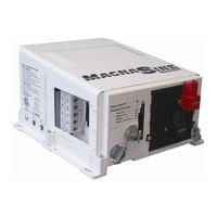
MS Series "MagnaSine" Pure Sine Wave Inverter/Charger
Brand:
Magnum
| Category:
Inverter
| Size: 2.1 MB
Table of Contents
Contact Information
2
Important Safety Instructions
3
Safety Information
3
Safety Precautions
3
Safety Symbols
3
Save These Instructions
3
Battery Safety
4
Table of Contents
7
1 Introduction
10
Regulatory Compliance
10
Features and Benefi Ts
11
Figure 1-1, Power Switch, Status LED, and Accessory Connection Ports
11
Figure 1-2, Electrical Connection Points
12
Figure 1-3, Left Side Features (MS2012, MS2812, MS2024, MS4024)
13
Figure 1-4, Left Side Features (MS2000 Series)
14
How an Inverter/Charger Works
14
Inverter Applications for Mobile Installations
14
Advantages of a Pure Sine Wave Vs Modifi Ed Sine Wave Inverter
15
Figure 1-5, AC Waveforms
15
Output Waveform
15
Appliances and Run Time
16
Table 1-1, Typical Appliance Power Consumption
16
2 Installation
17
Pre-Installation
17
Unpacking and Inspection
17
Figure 2-1, Simplifi Ed Installation Diagram for Permanent Installations
18
Locating the Inverter
19
Mounting the Inverter
20
Figure 2-2, Approved Mounting Positions
20
Figure 2-3, MS Series Dimensions and Side Reference
21
Wiring the Inverter - General Requirements
22
Wire Routing
22
Torque Requirements
22
DC Wiring
23
Figure 2-4, DC and Battery Temperature Sensor Wiring
24
Table 2-1, Recommended DC Wire/Overcurrent Device for Rated Use
25
DC Overcurrent Protection
25
DC Cable Connections
26
Figure 2-5, Battery Hardware Installation
26
Figure 2-6, Inverter DC Hardware Installation
26
Table 2-2, DC Wire Size for Increased Distance
26
Wiring the Battery Bank
27
Figure 2-7, Battery Temperature Sensor
28
Wiring the Inverter to the Battery Bank
29
AC Wiring
30
Ac Wire Size and Overcurrent Protection
30
Figure 2-8, AC Terminal Block
31
Table 2-3, AC Input/Output Wiring Confi Gurations (MS2012, MS2812, MS2024, MS4024)
33
Figure 2-9, AC Wiring for Single in - Single out (30 A) Confi Gurations
34
Inverter Loads
34
Figure 2-10, AC Wiring for Single in - Single out (60 A) Confi Gurations
35
Figure 2-11, AC Wiring for Single in - Dual out Confi Gurations
36
Figure 2-12, AC Wiring for Dual in - Single out Confi Gurations
37
Figure 2-13, AC Wiring for Dual in - Dual out Confi Gurations
38
Table 2-4, AC Input/Output Wiring Confi Gurations (MS2000 Models)
40
Figure 2-14, AC Wiring for MS2000 Models
41
Figure 2-15, AC Wiring for MS2000-15B/-20B Models
42
Grounding Inverters
43
Figure 2-16, Grounding System for MS Series
43
Figure 2-17, Multiple Connections to DC Ground Rod (Method 1)
44
Table 2-5, AC Grounding Electrode Conductor Sizing
44
Figure 2-18, Multiple Connections to DC Ground Rod (Method 2)
45
Figure 2-19, Single Connection to DC Ground Rod (Method 3)
45
Table 2-6, Equipment Grounding Conductor Sizing
46
Figure 2-20, Neutral-To-Ground Connection (Inverter Mode)
48
Figure 2-21, Neutral-To-Ground Connection (Standby Mode)
48
Neutral to Safety Ground Bonding
48
Figure 2-22, Disconnecting the Neutral-To-Ground Connection
49
Figure 2-23, Connecting a Large DC Ground Wire
49
Inverter Notifi Cation Requirements
50
Inverter Warning Label
50
Final Inspection
50
Figure 2-24, Warning Label
50
Functional Test
51
Figure 2-25, AC Voltage Checks
52
Figure 2-26, AC Voltage Checks (MS2000 Models)
52
Figure 2-27, AC Voltage Checks (MS2000-15B/20B Models)
52
3 Operation
53
Inverter Mode
53
Figure 3-1, Power Flow - Inverter Mode
53
Standby Mode
54
Battery Charging
54
Figure 3-2, Power Flow - Standby Mode
54
Figure 3-3, Automatic 4-Stage Charging Graph
55
Transfer Time
56
Battery Temperature Sensor Operation
56
Figure 3-4, BTS Temperature to Charge Voltage Change
56
Protection Circuitry Operation
57
Table 3-1, Inverter Battery Turn On/Off Levels
57
Inverter Startup
58
Figure 3-5, Power Switch and Status Indicator
58
Factory Default Values
59
Table 3-2, Inverter/Charger Default Values
59
Inverter Fan Operation
60
Using a Remote with the MS Series Inverter
60
Table 3-3, Inverter Compatibility Level
60
4 Maintenance and Troubleshooting
61
Recommended Inverter and Battery Care
61
Storage for Mobile Installations
61
Troubleshooting
62
Table 4-1, Basic Troubleshooting
62
Performing an Inverter Reset
63
Performing a Power Reset
63
Figure 4-1, Performing an Inverter Reset
63
Appendix A - Specifi Cations and Optional Equipment
64
Inverter/Charger Specifi Cations
64
Table A-1, Inverter/Charger Specifi Cations
64
Inverter Effi Ciency
65
AC Input Voltage to Output Charge Amps
65
Figure A-1, MS Series Effi Ciency Chart
65
Figure A-2, MS Series VAC Input to Charge Amps
65
Optional Equipment and Accessories
66
Appendix A - Specifi Cations and Optional Equipment
64
Appendix B - Battery Information
67
Battery Location
67
Battery Types
67
Battery Temperature
67
Battery Bank Sizing
67
Battery Bank Sizing Worksheet
68
Battery Wiring Confi Gurations
69
Figure B-1, Series Battery Wiring
69
Figure B-2, Parallel Battery Wiring
69
Figure B-3, Series-Parallel Battery Wiring
69
Figure B-4, Battery Bank Wiring Examples (12-Volt)
70
Figure B-5, Battery Bank Wiring Examples (24-Volt)
71
Appendix C - Inverter/Charger Terminology
72
Limited Warranty
74
How to Receive Repair Service
74
Advertisement
Related Products
Magnum MS2012
Magnum MS2024
Magnum MS2000
Magnum MS4024
Magnum MS4048
Magnum MMG35FHP
Magnum MMG50FHP
Magnum MMG55FH
Magnum MMG35FH
Magnum MMG 125
Magnum Categories
Bicycle
Tuner
Transceiver
Paint Sprayer
Portable Generator
More Magnum Manuals
Login
Sign In
OR
Sign in with Facebook
Sign in with Google
Upload manual
Upload from disk
Upload from URL