Sign In
Upload
Manuals
Brands
LXE Manuals
PDA
MX1-IS
LXE MX1-IS Manuals
Manuals and User Guides for LXE MX1-IS. We have
4
LXE MX1-IS manuals available for free PDF download: Reference Manual, User Manual
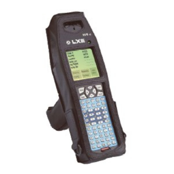
LXE MX1-IS Reference Manual (164 pages)
Intrinsically Safe
Brand:
LXE
| Category:
Handhelds
| Size: 1.37 MB
Table of Contents
Revision Notice
2
Table of Contents
3
Chapter 1 Introduction
11
Introduction
11
Figure 1-1 the MX1-IS Hand Held Computer
11
When to Use this Guide
12
Document Conventions
13
Getting Started
14
MX1-IS Components
15
The Protective Case
15
The Pistol Grip Handle
15
Figure 1-2 Components
15
Insert I-Safe Main Battery Pack
16
Figure 1-3 Open Battery Door
16
Figure 1-4 Inserting Battery Pack
16
Power on and off
17
Turn on the MX1-IS
17
Turn off the MX1-IS
17
Troubleshooting
17
Figure 1-5 Location of the Power Button
17
Adjust Display and Volume
18
Set the Display Contrast
18
Full Alpha-Numeric
18
Numeric-Alpha Keypad
18
Set the Beeper Volume
19
Full Alpha-Numeric
19
Numeric-Alpha Keypad
19
Intrinsically Safe Endcap
20
Scanner Endcap Indicators
20
Figure 1-6 Scanner Endcap
20
Figure 1-7 Scanner Endcap Leds and Beeper
20
Data Entry
21
Keypad Entry
21
Scanner Entry
21
Figure 1-8 Scan Beam
21
Getting Help
22
Manuals
22
Accessories
22
Chapter 2 Physical Description and Layout
23
Hardware Configuration
23
System Hardware
23
Figure 2-1 System Hardware
23
Central Processing Unit
24
AT Compatible Core Logic
24
System Memory
24
Upper Memory Block
24
Internal Flash Array
24
Video Subsystem
24
Power Supply
24
COM 1 Port
25
PCMCIA Slot
25
Physical Controls
26
On/Off Switch
26
Critical Suspend Mode and the off Timer
26
Figure 2-2 Location of the Power (PWR) Button
26
Power Status and the Status LED
27
Power Management and the Keypad
27
Figure 2-3 Power Status and the Status LED
27
Suspend State
28
Critical Suspend State
28
Display
29
Icons
29
Figure 2-4 MX1-IS Display
29
Display and Display Backlight Timer
30
Panning
31
Full Alpha-Numeric Keypad (60 Keys)
31
Numeric-Alpha Keypad (41 Keys)
31
Cleaning the Display/Scanner Aperture
31
Keypads
32
Figure 2-5 Keypads
32
Key Functions
33
Enter Key Function
33
Field Exit Key Function (IBM 5250 Only)
33
Figure 2-6 Three Special Use Keypads
33
Scan Key Function
33
2Nd Key Function
34
ALT Key Function
34
Arrow / Cursor Key Function
34
CTRL Key Function
34
SHFT Key Function
34
Alpha to Numeric Toggle with a
35
CAPS Mode
35
Mode Key Functions
35
SPC Key Function
35
Reset Key Sequence
35
Endcaps
36
Com1 / Com2
36
Scanner Endcaps
36
Scanner Endcap Leds and Beeper
36
Figure 2-7 Scanner Endcap Leds and Beeper
36
Miscellaneous Connectors
37
Handle Contacts
37
Figure 2-8 Handle Contacts
37
Chapter 3 Power Supply
39
Introduction
39
LXE Docking Cradles and the MX1-IS
39
About Lithium-Ion Batteries
39
Figure 3-1 Battery Compartment
39
Main Battery Pack
40
MULTI-Charger
40
Figure 3-2 Battery and Battery Charging Cup
40
Low Battery Warning
41
Status LED and the Battery
41
Handling Batteries Safely
41
Battery Maintenance Publication
41
Chapter 4 System Configuration
43
Introduction
43
Installed Software
43
Drive C Internal Flash Array
43
Software Loaded on Drive C
44
Directory Listing
45
C Root Directory
45
Agent
46
DOS Files
46
PCMCIA Files
47
Utils
48
Terminal Emulation Directories
49
Radio-Specific Subdirectory
50
PCTCP (2.4Ghz Radio Specific Files)
50
LXE 900Mhz Radio Files
50
Sample AUTOEXEC.BAT File
51
For 900Mhz Radio
51
For 2.4Ghz Radio (with ANSI Plus)
51
Sample CONFIG.SYS File
52
Radio NET.CFG Files
53
Lucent Radio NET.CFG File
53
Proxim Radio NET.CFG File
53
Sample SOCKET.CFG File
54
LXE DOS Terminal Emulations
56
Introduction
56
DOS Terminal Emulation User Defined Stored Forms
57
Dual Terminal Emulation
57
TE Selection Menu
57
Exiting Terminal Emulators
57
Menu Customization
57
Avalanche
58
Minimum Software Baseline
58
Upgrading the MX1-IS
58
Directory Structure
58
Agent
59
Ava
59
Apps
59
Apps\Avaf
59
BIOS Setup
60
Accessing the BIOS Setup
60
BIOS Setup Default Values by Option
60
Using the Keypad
61
Main Menu Options
62
Main Menu Parameters
62
Parameter Changes
62
Time
62
Boot
63
Date
63
Setup Msg
63
Post Msg
64
Summary
65
Advanced Menu Options
66
Parameter List
66
Power Management
67
Cpu
67
CPU and Suspend Timers and RF Communication
67
Power Mgt
67
Custom Setting
68
Disp BL
68
Display
68
Suspend
69
Off Timer
70
Docked PM
71
Power Key
71
Touch Wake
71
Troubleshooting
72
Keyboard
72
Caps
72
Numlock
72
Rpt Delay
72
Ctlaltdel
73
Rpt Rate
73
Other
73
COM1 Pin9
73
Font
73
Exit Menu Options
74
Save and Exit
74
Exit W/O Save
74
Load Defaults
74
Load Previous
74
Save Changes
74
Chapter 5 Utilities
75
Introduction
75
LXE Diagnostics
76
Display Utility (DISP35.EXE)
76
Keyboard Utility (KEY2335.EXE)
76
Parameter Auto-Detect Utility (PARAM35.EXE)
77
Set an API Function (SETAPI_4.EXE)
78
The NED ASCII Text Editor
79
NED Default Hot Keys
80
Chapter 6 RF Network Configuration
81
Introduction
81
SNMP DOS Agent
81
Avalanche
81
NET.CFG Parameters
81
Lucent Parameters
81
Link Support
81
Protocol
82
Wavelan_Network_Name
82
Station_Name
82
Ap_Distance
82
Microwave _Robustness
82
Transmit_Rate
83
Medium_Reservation
83
Card_Power_Management
83
Maximum_Sleep_Duration
83
Receive_All_Multicasts
83
Enable_Encryption
84
Transmit_Key_Id
84
Proxim Parameters
85
Link Support
85
Protocol
85
Int
85
Port
85
Mem#1 (ODI)
85
Domain
85
Station_Type
85
Socket
85
Initialize_365
85
Inactivity_Min
86
Inactivity_Sec
86
Channel
86
Subchannel
86
Mac_Optimize
86
Roam_Config
86
Peer_To_Peer
86
SOCKETS TCP/IP Stack
87
Introduction
87
Bootp
87
Dhcp
87
Setting SOCKETS.CFG Parameters
88
Set IP Address
88
Set ARP INIT
88
Set Interface
88
Set Router IP (Gateway Only)
88
Set Domain Name Server
88
Display IP Address
88
Options
89
SOCKET.CFG Parameters
89
Domain
89
Iface
90
Interface
90
Param
94
Route
96
Tcp
98
Chapter 7 Troubleshooting
101
Problem Determination Tips
101
Startup Problems
103
Bypassing the Configuration Files
103
Verifying Boot Order
103
Missing COMMAND.COM
104
Setting System Time and Date
104
Hardware Problems
105
Power Source
105
Keypad
105
Display
106
The Display Has Turned Dark or very Light
106
Hard Disk Drive
107
IRQ Assignments
107
Radio Problems
108
Software Related Problems
109
IP Stack
109
Memory
110
Conventional Memory
110
Extended Memory
110
System Testing
111
Power on Self Test (POST)
111
POST Error Messages
111
Messages Probably Requiring Repair
111
POST Beep Codes
112
If You Need Further Assistance
112
Appendixa Key Maps
113
Appendix A Key Maps
113
Full Alpha-Numeric Key Map (60 Key)
113
Full Alpha-Numeric Key Map 101-Key Equivalencies for Batch Units
113
IBM 3270 and TN3270 Terminal Emulator Keypad
118
IBM 5250 and TN5250 Terminal Emulator Keypad
118
Numeric-Alpha Key Map (41 Key)
119
Numeric-Alpha Key Map 101-Key Equivalencies for Batch Units
119
Appendixb Technical Specifications
125
Physical Specifications
125
Regulatory Classifications
126
Environmental Specifications
126
Display Specifications
127
Radio Specifications
127
PCMCIA 900 Mhz Type III (Obsolete)
127
PCMCIA 2.4 Ghz Type II - LXE 6500 Series
127
Revision History
128
Appendix C Commands
129
Appendixc Commands
129
Introduction
129
REMDISK, REMSERV, PRINT, SYS.COM and the MX1-IS
129
ROM-DOS Commands
129
Ansi.sys
130
Attrib.exe
131
Chkdsk.exe
132
Command.com
133
Deltree.exe
134
Format.com
135
Himem.sys
137
Mem.exe
138
Mode.com
139
More.com
140
NED.EXE and NED.CFG
141
NED Default Hot Keys
143
Print.com
144
Remdisk.exe
145
Remserv.exe
147
Sys.com
149
Ver
150
Xcopy.com
151
ROM-DOS 6.22 Command Summary
152
Index
157
Advertisement
LXE MX1-IS Reference Manual (100 pages)
Single Docking Cradle
Brand:
LXE
| Category:
Handhelds
| Size: 2.71 MB
Table of Contents
Table of Contents
3
Chapter 1 Introduction
9
Single Docking Cradle
9
Figure 1-1 Vehicle Mount Docking Cradle Charging/Communicating Device
9
Document Conventions
10
Quick Start
11
Figure 1-2 Insert Device into Cradle
11
Figure 1-3 Wall, Vehicle and Desk Cradle Components
12
Compatible Devices
13
Figure 1-4 Compatible Devices
13
Battery Charging Contacts
14
Figure 1-5 Cradle Connectors on the Hand Held Devices
14
Obsolete Equipment
15
Software/Hardware Upgrades Required for the 2330 Only
15
Retainer Clip for 2330 Required
15
Maintenance
16
Storage Cradle
16
Vehicle Mount Assembly
16
Docking Cradle Configurations
17
Docking Cradle Components
18
Figure 1-6 Passive Storage Cradle
18
Figure 1-7 Power/Charging and Communications Module
18
Passive Storage Cradle
18
Power/Charging and Communications Module
18
Battery Charging Subsystem
19
IR to RS232 Interface
19
Power Subsystem
19
Figure 1-8 Mounting Bracket Assemblies
20
Mounting Brackets
20
Powered Cradle Indicators
21
Power on
21
Battery Charging Status
21
Figure 1-9 Status Indicators
21
Figure 1-10 Battery Charging Status Indicators
21
IR-RS232 Status
22
Cradle Connectors
22
Power Switch, Power Cable and RS232 Connector
22
Docking Cradle Label
22
Figure 1-11 IR-RS232 Status Indicator
22
Figure 1-12 On/Off Switch and Cable Connectors
22
Figure 1-13 Nameplate Label on Docking Cradle
22
AC Adapters for Docking Stations (Optional)
23
US AC Wall Adapter
23
International AC Adapter
23
Figure 1-14 US AC/DC 12V Power Supply
23
Figure 1-15 International AC/DC 12V Power Supply
23
Getting Help
24
User Guides
24
Accessories
24
Chapter 2 Installation
27
Introduction
27
Figure 2-1 Vehicle, Desktop and Wall Mounted Cradle Components
27
Before Assembly Begins
28
General Components
29
Vehicle Mount Components
30
Table Mount Components
31
Wall Mount Components
31
Putting It All Together
32
Attach Power Communications Module to Cradle
32
Table Mount Assembly
33
Wall Mount Assembly
35
Vehicle Mount Assembly
37
Step 1 - Prepare Cradle
37
Step 2 - Mount Bottom Mounting Bracket to Vehicle
39
Step 3 - Prepare the Cradle Mounting Assembly
41
Step 4 - Connect Cradle to Vehicle Bracket
42
Power Supplies and Cable Connections
43
AC Power Supply
43
Figure 2-2 120/240VAC Input to DC Power Supply
43
Vehicle Power Connections
44
Foreign Language Translations
44
Figure 2-3 24/60 VDC Input to Power Supply Providing 12VDC Output (Shown Without Fuse)
45
Figure 2-4 Vehicle Power Supply, 24 - 60VDC (Fuse Not Shown)
45
Figure 2-5 Connecting the Power Supply to the Vehicle
45
Vehicle 24/60VDC Input Cable Connection
45
Figure 2-6 Vehicle Connection Wiring Color Codes
46
Figure 2-7 8 - 18 VDC Direct Vehicle Connection (Shown Without Fuse)
47
Figure 2-8 Direct Vehicle Power Connection (Fuse Not Shown)
47
Figure 2-9 Connecting the Power Supply to the Vehicle
47
Vehicle 8-18VDC Direct Connection
47
Figure 2-10 Vehicle Connection Wiring Color Codes
48
Connect RS232 Cable
49
Connect Using 25-Pin or 9-Pin Printer/Pc Cable
49
Connect Using DIN Cable
49
Figure 2-11 D9 to DIN Printer Cable
49
Docking Cradle End Molex Connector Location
50
Figure 2-12 Docking Cradle End Molex Connector
50
Chapter 3 Using the Docking Cradle
51
Introduction
51
Prepare Mobile Device for Docking Cradle
51
Turn off the 2330
51
Figure 3-1 Turn 2330 off
51
Turn off the 2335 and MX1
52
Insert Main Battery Pack in Mobile Device
52
Figure 3-2 Location of the Power Button on the 2335 and MX1
52
Figure 3-3 Insert Battery and Close Cover
52
Insert Mobile Device in Powered Cradle
53
Figure 3-4 Spring Clips and Power/Battery Contacts
53
Figure 3-5 Insert Device in Cradle
53
Data Transfer Methods
54
Cables
54
RS232 Serial Port on the Docking Cradle
55
Figure 3-6 Male 9-Pin Connector on the PCM
55
Figure 3-7 RS232 Serial Port Pinout on the PCM
55
Sending Data to an External Computer
56
Receiving Data from an External Computer
57
Serial File Transfer Utility Using ROM-DOS Commands
58
Remserv
58
Remdisk
59
Serial File Transfer Using MS-DOS Commands
60
Transferring Files Using MS-DOS INTERLNK / INTERSVR
60
IR Port
62
Figure 3-8 PCM and IR Ports Line up
62
Sending Data to a Printer with an IR Port
63
Sending Data to a Printer Without an IR Port
63
Chapter 4 Multidock and Ac/DC Singledocks
65
Introduction
65
Figure 4-1 Multidock and Singledocks
65
Multidock
66
Installation
66
Guidelines
66
Procedure
67
Features
67
Components
67
Front Panel Indicators
68
Specifications
68
Figure 4-3 Multidock Indicators
68
RS485 Converter
69
Terminator
69
RS485 Comm Port
70
Figure 4-2 Multidock
71
AC or DC Single Dock
72
AC Singledock
72
Components
72
Figure 4-4 AC or DC Singledock
72
Specifications
72
AC Singledock Installation
73
Figure 4-5 AC Singledock Indicators
73
Indicators
73
DC Singledock
74
DC Singledock Installation
74
Figure 4-6 DC Singledock Indicators
74
Indicators
74
Components
75
Specifications
75
Modem
76
Installation
76
Figure 4-7 Modem Connectors and Dip Switches
76
Components
77
Indicators
77
Figure 4-8 Modem Indicators
77
Dip Switch Settings
78
Modem / PC Setup
79
Figure 4-9 Modem Connections
79
Mounting Brackets for Multidocks, AC and DC Singledocks
80
Mounting Multidock to Wall
80
Mounting AC Singledock to Wall
80
Mounting in Sequence
81
Figure 4-10 Mounting Diagrams
81
Vehicle Mounting and the DC Singledock
82
LXE Vehicle Bracket
82
Figure 4-11 Fasten Backplate Assembly to DC Singledock
83
Cable Port Connections
84
Multidock Cabling
84
AC Singledock Cabling
84
Figure 4-12 Multidock Cable Ports
84
Figure 4-13 AC Singledock Cable Ports
84
DC Singledock Cabling
85
Modem Cabling
85
Figure 4-14 DC Singledock Cable Ports (Port on Right Side Is Not Connected)
85
Power Adapter, 110-240 VAC
86
Vehicle 12VDC Connection
87
Fuse Replacement
87
Figure 4-15 Proper Connection of the Vehicle Cable
87
Chapter 5 Battery Pack Chargers
89
Introduction
89
Handling Batteries Safely
89
Battery Warning Messages on Computers
89
Optional Clip-On Portable Charger for the 2335 and MX1
90
Clip-On Portable Charger Leds
90
Figure 5-1 Clip-On Portable Charger
90
Main Battery Pack Charger for the Mobile Device
91
Figure 5-2 Main Battery Pack Chargers / Analyzers
91
Figure 5-3 1500 Mah (Nimh) Main Battery
91
Figure 5-4 Six Cup Charger/Analyzer
92
Figure 5-5 Back View of a Charger/Analyzer
92
Using a 3 or 6 Bay Charger/Analyzer
94
Getting Started
94
Power on
94
Figure 5-6 Sample Diagnostic Display
94
Insert Battery
95
Select a Function
95
Figure 5-7 Battery Pack and Charging Cup
95
AC Adapters for 3 and 6 Bay Battery Chargers
96
US AC Wall Adapter
96
International AC Adapter
96
Figure 5-8 US AC/DC 12V Power Supply
96
Figure 5-9 International AC/DC 12V Power Supply
96
Index
97
LXE MX1-IS User Manual (54 pages)
LXE MX1-IS: User Guide
Brand:
LXE
| Category:
Handhelds
| Size: 1.56 MB
Table of Contents
Revision Notice
2
Table of Contents
3
Features of the Mx1 Intrinsically Safe Hand Held Computer
7
Introduction
7
Figure 1 the MX1-IS Hand Held Computer
7
Important Safety Instruction and Warnings
8
Scanner Warnings and Labels
10
Figure 2 Scanner Module, Top
10
Figure 3 Other Equipment Labeling
10
Figure 4 Caution Labels - Scanner Module, Back
10
Figure 5 Caution Labels - Scanner
10
MX1 I-Safe Components
11
The Protective Case
11
The Pistol Grip Handle
11
Figure 6 MX1-IS Components
11
Display
12
Icons
12
Cleaning the Glass Display/Scanner Aperture
12
Figure 7 MX1-IS Display
12
Display Backlight
13
Display Backlight Timer
13
Panning
13
Intrinsically Safe Endcap
14
Scanner Endcap
14
Scanner Endcap Indicators
14
Figure 8 Scanner Endcap
14
Figure 9 Scanner Endcap Leds and Beeper
14
Keypad Controls
15
Full Alpha-Numeric (60 Key)
15
Figure 10 the Alpha-Numeric Keypads
15
Numeric-Alpha (41 Key)
16
Scan Key Function
16
Enter Key Function
16
Field Exit Key Function (IBM 5250 Only)
16
Arrow / Cursor Key Function
16
Figure 11 the Numeric-Alpha Keypad
16
2Nd Key Function
17
CTRL Key Function
17
ALT Key Function
17
SHFT Key Function
17
SPC Key Function
17
Mode Key Functions
18
CAPS Mode
18
Alpha to Numeric Toggle with a
18
Keypress Sequences
18
Reset Key Sequence
18
Power Button Functions
19
Off Timer and Critical Suspend Mode
19
Figure 12 Location of the Power (PWR) Button
19
Power Status and the Status LED
20
Power Management and the Keypad
20
Figure 13 Power Status and the Status LED
20
Getting Help
21
Manuals
21
Accessories
21
Operation
23
Insert I-Safe Main Battery Pack
23
Figure 14 Open Battery Door
23
Power on and off
24
Turn on the MX1-IS
24
Turn off the MX1-IS
24
Figure 15 Location of the Power Button
24
Adjust Display and Volume
25
Set the Display Contrast
25
Full Alpha-Numeric
25
Numeric-Alpha Keypad
25
Set the Beeper Volume
25
Enter Data
26
Keypad Entry
26
Scanner Entry
26
Figure 16 Scan Beam
26
MX1-IS Environmental Specifications
27
I-Safe Main Battery
27
Battery Pack
27
Critical Suspend State
27
Battery Charger
28
Optional LXE MULTI-Charger
28
Figure 17 MX1-IS Battery and Charging Cup
28
Appendixa Key Maps
29
Appendix A Keymaps
29
Full Alpha-Numeric Key Map (60 Key)
29
Figure 18 Full Alpha-Numeric Keypad
29
Full Alpha-Numeric Key Map 101-Key Equivalencies for DOS Units
30
IBM 3270 and TN3270 Terminal Emulator Keypad
35
Figure 19 IBM 3270 Specific Keypad
35
IBM 5250 and TN5250 Terminal Emulator Keypad
36
Figure 20 IBM 5250 Specific Keypad
36
Numeric-Alpha Key Map (41 Key)
37
Figure 21 Numeric-Alpha Keypad
37
Numeric-Alpha Key Map 101-Key Equivalencies for Batch Units
38
Appendixb Regulatory Notices and Safety Information
43
Appendixbregulatorynotices Andsafetyinformation
44
Approvals
44
Laser Light Safety Statement
49
Revision History
51
Index
53
Advertisement
LXE MX1-IS User Manual (38 pages)
Wavelink Avalanche
Brand:
LXE
| Category:
PDA
| Size: 0.69 MB
Table of Contents
Table of Contents
3
Chapter 1 Introduction
7
About this Manual
7
Overview
7
Avalanche Management Console
7
Avalanche Agent
8
Avalanche Enablers
8
Limitations of DOS Devices
8
Supported Computers
9
Supported Radios
9
Supported DOS Terminal Emulations
9
Configurable Parameters
10
Radio Parameters
10
Cisco 350 Radios
10
Lucent/Agere P1 Radios
10
Symbol 4121 Radios
10
Network Configuration Parameters
10
Terminal Emulation Parameters
10
Installation
11
Installation of Wavelink Software
11
Installation of LXE Package Builder
11
Installation of Enablers on LXE Computers
11
Operation
12
How to Use this Guide
12
Document Conventions
12
Getting Help
13
LXE Manuals
13
Wavelink Manuals
13
Chapter 2 LXE Features
15
Introduction
15
Communication Overview
15
Communication Using a Dock or Cradle
16
Configuring the Agent
16
Step 1: Detect COM Ports in Avalanche Manager
16
Step 2: Stop the Avalanche Service
16
Step 3: Modify the Avalanche Properties File
16
Step 4: Restart the Avalanche Service
17
LXE Package Builder
18
Using the GUI Interface
18
Figure 2-1 Select G-Number
18
Figure 2-2 Select Output Directory
19
Figure 2-3 End of Conversion Message
19
Using the Command Line Interface
20
Syntax Examples
20
Using Avalanche
21
Figure 2-4 Avalanche Management Console Components
21
Software Collections
23
Auto Run Software Packages
24
Figure 2-5 Software Collection
24
Figure 2-6 Sample Auto Run Software Package
24
Application Software Packages
25
Figure 2-7 Sample Application Software Package
25
Figure 2-8 Sample Support Software Package
26
Support Software Packages
26
Configuration
27
Terminal Emulation Parameters
27
Figure 2-9 Accessing the te Configuration Menu
27
Figure 2-10 the Configuration Menu
27
Radio and Network Parameters
29
Figure 2-11 Accessing Network Profile Configuration
29
Figure 2-12 Network Profile, Control Tab
29
Figure 2-13 Network Profile, Routing Tab
30
Figure 2-14 Network Profile, Security Tab
31
Figure 2-15 Static WEP Keys
32
Manual Network and Radio Parameter Configuration
32
Filtering LXE Computers
33
By Computer Type
33
By Radio Type
33
Figure 2-16 Filtering Devices by LXE Computer Type
33
Figure 2-17 Filtering Devices by Radio Type
33
Appendixa Dos Computer Software Load
35
Appendix A Dos Computer Software Load
35
Minimum Software Baseline
35
Upgrading LXE Computers
35
Directory Structure
35
Agent
36
Ava
36
Apps
36
Apps\Avaf
36
Index
37
Advertisement
Related Products
LXE MX3
LXE MX3X
LXE MX7
LXE MX5
LXE MX8
LXE MX2
LXE MX6 PPC
LXE MX1 Intrinsically Safe
LXE MX1ISA378
LXE MX1ISA378CHGR3WW
LXE Categories
Handhelds
Automobile Accessories
Battery Charger
PDA
Desktop
More LXE Manuals
Login
Sign In
OR
Sign in with Facebook
Sign in with Google
Upload manual
Upload from disk
Upload from URL