Sign In
Upload
Manuals
Brands
Linhai Manuals
Offroad Vehicle
LH400CUV-2
User Manuals: Linhai LH400CUV-2 Utility Vehicle
Manuals and User Guides for Linhai LH400CUV-2 Utility Vehicle. We have
1
Linhai LH400CUV-2 Utility Vehicle manual available for free PDF download: Service Manual
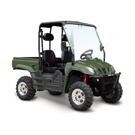
Linhai LH400CUV-2 Service Manual (209 pages)
Brand:
Linhai
| Category:
Offroad Vehicle
| Size: 14 MB
Table of Contents
Important Information
2
Table of Contents
3
General Information
5
Important Information
6
Preparation for Removal Procedures
6
Replacement Parts
6
Gaskets,Oil Seals and O-Rings
6
Checking of Connections
7
Conversion Table
8
Metric to Imp
8
V.I.n and Engine Serial Number
9
Vehicle Dimensions
10
Maintenance
12
Periodic Maintenance Schedule
13
Periodic Maintenance
13
Engine
14
Transmission
15
Lubricant and Fluid
16
Brakes
16
Lubrication Recommendations
18
Throttle Pedal Inspection
18
Throttle Freeplay
18
Throttle Freeplay Inspection
18
Choke Adjustment
19
Fuel System
19
Fuel Lines
19
Toe Alignment
20
Vent Lines and Roll over Valve
20
Fuel Filter
20
Braking System Inspection
21
Brake Pad Inspection
21
Hose/Fitting Inspection
21
Adjusting the Brake Pedal
21
Adjusting the Parking Brake
22
Suspension Spring Rpeload Adjustment
23
Front Suspension
23
Rear Suspension
23
Wheels
23
Tire Inspection
24
Tire Pressure
24
Wheel Nut Torque Specifications
24
Wheel Installation
24
Frame , Nuts, Bolts, Fasteners
25
Tire Tread Depth
25
CHAPTER 3 ENGINE ATV SERVICE MANUAL 2005/ Version Number
27
Maintenance Specifications
28
Parts Inspection and Service
34
Valve Clearance Adjustment
34
Valve Clearance
34
Idling Speed Adjustment
35
Spark Plug Inspection
36
Compression Pressure Measurement
37
Recommended Engine Oil
38
Engine Oil Level Inspection
38
Engine Oil Replacement
39
Engine Oil Pressure Inspection
39
Coolant Level Inspection
40
Coolantre Placement
40
Radiator
41
Handling Notes for Coolant
42
Cylinder Head
43
Cylinder Head Removal
45
Cylinder Head Inspection
45
Cyinder Head Installation
46
Camshaft and Rocker Arms
48
Cam Lobes Length
49
Cam Shaft Inspection
49
Rocker Arm and Rocker Arm Shaft Removal
49
Rocker Arms and Rocker Arm Shafts Inspection
50
Camshaft and Rocker Arm Installation
50
Valves and Valve Springs
52
Valves and Valve Springs Removal
53
Valve and Valve Springs Inspection
53
Valve Seats Inspection
54
Valves and Valve Springs Installation
56
Cylinder and Piston
58
Piston and Piston Rings Removal
59
Cylinder Inspection
59
Piston and Piston Pin Inspection
60
Piston Rings Inspection
61
Piston Rings, Piston and Cylinder Installation
61
Engine Oil
63
Primary Sheave
65
Secondary Sheave
66
Primary Sheave Removal
67
Secondary Sheave and V-Belt Removal
67
Secondary Sheave Disassembly
68
Clutch Inspection
68
V-Belt Inspection
68
Weight Inspection
69
Secondary Sheave Inspection
69
Primary Sheave Assembly
69
Secondary Sheave Installation
70
A.C. Magneto and Starter Clutch
72
Magneto Cover and Stator Coil
72
A. C. Magneto and Starter Clutch
73
A.C. Magneto Rotor Removal
74
Starter Drive Gear Inspection
74
A.C. Magneto Rotor Installation
75
Oil Pump
76
Oil Pump Inspection
77
Crankcase and Crankshaft
78
Crankcase and Crankshaft Removal
79
Crankshaft Removal
80
Crankshaft Inspection
80
Crankcase Installation
81
Cooling System
82
Water Pump
84
Thermostat
88
Chassis
96
Front A-Arm Replacement
97
Rear A-Arm Replacement
98
Rear Stabilizer Bar Removal/Installation
101
Front Strut Replacement
103
Front Strut Ball Joint Replacement
104
Box Removal
105
Box Installating
105
Steering Assembly Removal/Installation
106
Final Drive
108
Front Hub Removal/Inspection
109
Front Hub Exploded View
109
Wheel, Hub, and Spindle Torque Table
109
Front Hub Bearing Replacement
111
Front Drive Axle Removal/Inspection (4X4)
112
Front Drive Axle Installation (4X4)
113
Chapter1
113
Chapter2
113
Front Drive Axle Disassembly/ Inspection(4X4)
114
Inner CV Joint Inspection
114
Front Drive Axle Assembly (4X4)
116
Rear Hub Exploded View
117
Rear Hub and Knuckle Removal/ Inspection
118
Rear Hub and Knuckle Installation
118
Rear Drive Shaft Removal
119
Rear Drive Shaft Installation
119
Rear Gear Case Exploded View
121
Rear Gearcase Disassembly
122
Rear Gearcase Assembly
122
Backlash Inspection
123
Front Gearcase Slip Limit Torque Test
123
Front Gearcase Disassembly/ Inspection
124
Front Gearcase Assembly
127
Front Diffrential Disassembly/ Inspection
129
Front Diffrential Assembly
131
Front Gearcase Exploded View
133
Rear, Front Prop Shaft Removal
134
Transmission
136
Gear Shifter Removal
137
Shifter Disassembly
137
Shifter Assembly
138
Shifter Installation
139
Shift Linkage Adjustment
139
Engine and Transmission Removal
140
Chapter3
140
Engine and Transmssion Install
142
Transmission Disassembly
143
Transmission Assembly
144
Chapter4
146
Chapter5
146
Trouble Shooting Checklist
147
Chapter6
147
2X4 Transmission Exploded View
148
4X4 Transmission Exploded View
149
Brakes
151
Burnishing Procedure
153
Brake Bleeding-Fluid Change
153
Parking Brake and Brake Line Inspection
155
Chapter7
155
Parking Brake Adjustment
156
Parking Brake Inspection
156
Parking Brake Rear Caliper Removal / Install
157
Front Pad Removal / Inspection / Installation
157
Front Disc Inspection
159
Front Caliper Removal/ Inspection / Installation
160
Rear Brake Pad Removal/ Inspection / Installation
161
Rear Caliper Removal/ Inspection/ Installation
162
Rear Brake Disc Inspection
163
Electrical
166
Headlight Adjustment
167
Taillight / Brakelight Lamp Replacement
168
Chapter8
168
Battery
169
Battery Inspection / Removal
169
Open Circuit Voltage Test
170
Load Test
170
Battery Testing
170
Battery Installation
170
Ignition System Troubleshooting
171
No Spark, Weak or Intermittent Spark
171
Circuit Diagram
172
If the Ignition System Fails to Operate
173
Charging System
177
Charging System Circuit Diagram
177
Current Draw - Key off
177
Electrics Starting System
180
If the Starter Motor Fails to Operate
181
If the Fan Motor Fails to Turn
184
If the Heat Alarm Unit Working
187
Lighting System
189
Light System Check
192
The Taillight Fails to Come on
193
Reverse Limit System
194
Gear Position Indicator Switch Test
195
Switch Table
195
Switch Schematic
196
Speedmeter System
197
Operation of Spped Sensor
197
Main Technical Parameter:
198
Main Switch and Handle Switch
200
Fuel Gauge/ Fuel Level Sensor
201
The Operation Principle of the Electric 4Wd Shift
203
Wiring Diagram
206
Advertisement
Advertisement
Related Products
Linhai LH40DA
Linhai LH400ATV-2B
Linhai LH500ATV-D
Linhai Landboss LH800U-2DL
Linhai Landboss LH800U-2D
Linhai Landboss LH800U-2DR
Linhai LH50DU
Linhai LH1100U-D
Linhai LH125T
Linhai 2004 ATV 260
Linhai Categories
Offroad Vehicle
Utility Vehicle
Motorcycle
Automobile
Scooter
More Linhai Manuals
Login
Sign In
OR
Sign in with Facebook
Sign in with Google
Upload manual
Upload from disk
Upload from URL