Sign In
Upload
Manuals
Brands
Lincoln Electric Manuals
Welding System
SVM143-A
Lincoln Electric SVM143-A Manuals
Manuals and User Guides for Lincoln Electric SVM143-A. We have
1
Lincoln Electric SVM143-A manual available for free PDF download: Operator's Manual
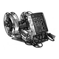
Lincoln Electric SVM143-A Operator's Manual (98 pages)
Heads & Controls Boom Mount or Bench Models
Brand:
Lincoln Electric
| Category:
Welding System
| Size: 1 MB
Table of Contents
V V Master for All Sections
6
California Proposition 65 Warnings
2
Electric and Magnetic Fields
2
Electric Shock Can Kill
3
Safety
3
Fumes and Gases
3
Table of Contents
6
Installation
8
Technical Specifications - DH-10 Complete Units or Controls & Heads
8
General Description
9
Recommended Processes and Equipment
9
Available Models
9
Safety Precautions
10
Installation of the DH-10 Boom Mount Wire Feeder Components
10
Mounting Single Head Wire Drive Unit (K679-1
10
Mounting Single Head Wire Drive Unit (K679-1 or -2)
10
Mounting the DH Double Header Wire Drive Unit (K1497-1 or -2)
10
Mounting the DH-10 Control Box (K1496-1
10
Connecting Wire Drive Unit to Control Box
11
Control Speed Range Setting
11
Double Header (DH) Wire Drive Ratio Selection
11
Electrode Routing
11
Wire Drive Speed Range Selection
11
Procedure to Install Drive Roll and Wire Guides
12
Wire Feed Drive Roll Kits
12
DH Drive Roll Kit Installation (KP1505 and KP1507
13
GMAW Guns
13
Gun and Cable Assemblies with Standard Connection
13
Innershield Guns
13
Single Drive 4-Roll Kits (KP655 and KP656
13
DH Double Head Drives
14
DH Double Head Drives Water Connections (for Water Cooled Guns
14
GMAW Guns
14
Gun and Cable Assemblies with Fast-Mate Connection
14
Gun Cable Connection with Fast-Mate Connection
14
Gun Cable Connection with Standard Connection
14
Single Head Drives (K679
14
Electrical Installation
15
GMAW Shielding Gas
15
Input Cable: DH-10 Control to Power Source
15
Optional Features Installation
16
-Operation Section-
19
Dh-10 Control Switch Setup
20
Duty Cycle
20
Operation
20
Setup DIP Switch Access
20
Setting the DIP Switches
20
Wire Drive Head Selection
20
Welding Power Source Selection
21
Metric/English Wire Feed Speed Display Selection
22
4-Step Trigger Mode Operation Selection
22
Low Security Mode Selection
23
High Security Mode Selection
23
Safety Precautions
20
Keypad and Display Operation
23
Keypad and Display Description
23
Power-Down Save
23
Operation Keys
24
Trigger Mode Selection
24
Display Control Keys
25
Digital "Memory" Voltmeter
25
Acceleration Selection
25
Dual Procedure Remote Control (K1449-1
26
Dual Procedure Remote Control (K1449-1)
26
Security Modes
26
Wire Reel Loading - Readi-Reel, Spools or Coils
26
Wire Reel Loading - Readi-Reels, Spools or Coils
26
To Mount a 30 Lb (14 Kg) Readi-Reel Package
26
To Mount 10 to 44 Lb (4.5 to 20 Kg) Spools (12 In/300 MM Diameter) or 14 Lb (6 Kg) Innershield Coils (FIGURE
27
To Mount a 50 to 60 Lb (22.7 to 27.2 Kg) Coil: (Using K1504-1 Coil Reel
27
Drive Roll Pressure Setting
28
Feeding Electrode and Brake Adjustment
28
Gas Guard Regulator Setting
28
Making a Weld
28
Procedure for Setting Angle of Feedplate
28
Loss of Voltage Sense Shutdown
29
Wire Feed Overload Protection
29
Wire Reel Changing
29
Explanation of Prompting and Error Messages
30
Grounding Lead Protector
30
-Accessories Section-
31
Accessories Section
31
Accessories
32
Drive Roll and Guide Tube Kits
32
General
32
Accessories
33
Input Cable Assemblies
34
Spindle Adapters
34
Gun Adapters (for DH Wire Drive Heads
35
Gun and Cable Assemblies
35
Maintenance Section
37
Periodic Maintenance
37
Maintenance
38
Safety Precautions
38
Routine Maintenance
38
Wire Reel Mounting - Readi-Reels and
38
Avoiding Wire Feeding Problems
38
Periodic Maintenance
39
Gun and Cable Maintenance
39
Wire Drive Motor and Gearbox
39
Procedure for Removing Feedplate from Wire Feeder
39
Theory of Operation
41
Theory of Operation Section
41
Control Board
42
General Description
42
Theory of Operation
42
Theory of Operation
43
Input Receptacle, Control Board, and Operator Controls
43
Wire Feed Heads and Receptacles
44
-Troubleshooting and Repair Section-
45
How to Use Troubleshooting Guide
46
Electric Shock
47
PC Board Troubleshooting Procedures
47
Troubleshooting and Repair
48
Troubleshooting Guide
49
Troubleshooting and Repair
50
Test Procedures
61
Wire Drive Motor Test
61
Test Procedure
62
Tach Adjustment and Feedback Test
63
Keypad Resistance Test
67
Encoder PC Board Test
71
Gas Solenoid Test
73
Component Replacement Procedures
75
Display PC Board Removal and Replacement
75
Removal Procedure
76
Replacement Procedure
76
Gas Solenoid Removal and Replacement
77
Encoder PC Board Removal and Replacement
79
Wire Drive Motor and Gear Box Removal and Replacement
81
Replacement Procedures
84
Retest after Repair
85
Electrical Diagrams
88
Electrical Diagrams
90
Wiring Diagram (Wire Drive) (M17871
90
Control Board Schmatic (Sheet 1) (G3040-1
91
Display Board Schematic (L10138
93
Encoder Board Schematic (S22066
94
Electrical Diagrams
95
Control Board Layout (G3041-2
95
Display Board Layout (L10139-1
96
Encoder Board Layout (M17797-1
97
Advertisement
Advertisement
Related Products
Lincoln Electric COMMANDER SVM145-B
Lincoln Electric PRO-CUT SVM146-A
Lincoln Electric RANGER SVM148-B
Lincoln Electric SQUARE WAVE SVM141-A
Lincoln Electric SVM189-B
Lincoln Electric CLASSIC I SVM134-A
Lincoln Electric POWER MIG SVM157-A
Lincoln Electric POWER MIG SVM165-A
Lincoln Electric RANGER SVM120-A
Lincoln Electric SQUARE WAVE SVM118-A
Lincoln Electric Categories
Welding System
Welding Accessories
Flashlight
Wire Feeders
Portable Generator
More Lincoln Electric Manuals
Login
Sign In
OR
Sign in with Facebook
Sign in with Google
Upload manual
Upload from disk
Upload from URL