Sign In
Upload
Manuals
Brands
Lincoln Electric Manuals
Welding System
POWER WAVE S500
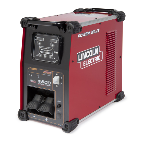
Lincoln Electric POWER WAVE S500 Manuals
Manuals and User Guides for Lincoln Electric POWER WAVE S500. We have
5
Lincoln Electric POWER WAVE S500 manuals available for free PDF download: Service Manual, Operator's Manual
Lincoln Electric POWER WAVE S500 Service Manual (163 pages)
Brand:
Lincoln Electric
| Category:
Welding System
| Size: 13.65 MB
Table of Contents
Service Manual
1
Electric and Magnetic Fields May be Dangerous
2
Safety
2
For Engine Powered Equipment
2
California Proposition 65 Warnings
2
Electric Shock Can Kill
3
Arc Rays Can Burn
3
Fumes and Gases Can be Dangerous
3
Welding and Cutting Sparks Can Cause Fire or Explosion
4
Cylinder May Explode if Damaged
4
For Electrically Powered Equipment
4
Assessment of Area
6
Installation and Use
6
Electromagnetic Compatibility (EMC)
6
Methods of Reducing Emissions
7
Safety
7
Table of Contents
8
Technical Specifications-Power Wave S500
10
Installation
10
Welding Process
11
Physical Dimensions
11
Machine Grounding
12
Installation
12
Lifting
12
Select Suitable Location
12
Input Fuse and Supply Wire Considerations
13
Input Voltage Selection
13
Power Wave S500
13
Input Connection
13
Connection Diagrams
14
Gtaw (TIG) Welding
14
TIG with S-Series User Interface
14
Stick with S-Series User Interface
15
Smaw (Stick) Welding
15
Gmaw (Mig) Welding
16
Mig Process
16
Recommended Work Cable Sizes for ARC Welding
17
General Guidelines
17
Output Cable Guidelines
17
Cable Inductance and Its Effects on Welding
18
Remote Sense Lead Specifications
18
Voltage Sensing Overview
18
Negative Electrode Polarity
19
Work Voltage Sensing
19
Electrode Voltage Sensing
19
General Guidelines for Voltage Sense Leads
19
Voltage Sensing Considerations for Multiple ARC Systems
20
If Sense Leads Are Not Used
20
If Sense Leads Are Used
20
Control Cable Connections
22
Connection between Power Source and Ethernet Networks
22
Product Specific Installation Instructions
22
Operation Section
23
Graphic Symbols that Appear on this Machine or in this Manual
24
Power-Up Sequence
24
Safety Precautions
24
Duty Cycle
24
Product Description
25
Product Summary
25
Recommended Processes and Equipment
25
Equipment Limitations
25
Operation
25
Design Features
26
Loaded with Standard Features
26
Case Front Controls
26
Case Back Controls
27
Basic Welding Controls
28
Common Welding Procedures
28
Definition of Welding Modes
28
Constant Voltage Welding Synergic CV
29
Non Synergic CV
29
All CV Modes
29
Pulse Welding
29
Accessories Section
31
Kits, Options and Accessories
32
General Options
32
Factory Installed Options
32
Field Installed Options
32
Stick Options
33
Maintenance Section
35
Routine Maintenance
36
Periodic Maintenance
36
Calibration Specification
36
Major Components Locations
37
Theory of Operation Section
39
General Description
40
Theory of Operation
40
Line Switch, Input Board and Power Factor Control (PFC) Board
41
Power Conversion Board Assembly
42
Six Phase Chopper Board and Multi-Phase Output Choke
43
DC Bus Board and Digital Control Board
44
Optional Remote Control Board and 115VAC Inverter Board
45
Machine Protection
46
Thermal Protection
46
Protective Circuits
46
Over Current Protection
46
Insulated Gate Bipolar Transistor (IGBT) Operation
47
Pulse Width Modulation
47
Troubleshooting and Repair
49
Рow to Use Troubleshooting Guide
50
PC Board Troubleshooting Procedures
51
Troubleshooting and Repair
52
Output Problems
53
Welding Problems
55
Ethernet Problems
57
Input Control Board
58
Main Control Board (“Status” Light)
59
Case Cover Removal and DC Link Capacitor Discharge Procedure
61
Materials Needed
61
Test Description
61
Case Cover Removal
62
Removal Procedure
62
Capacitor Discharge Procedure
63
Replacement Procedure
64
PFC Control Board Test
65
PFC Control Board Location
66
PFC Control Board Error Codes
67
PFC Control Board Led and Test Points
67
PFC Control Board Led Description and Functions
67
PFC Control Board Diode Checks
68
PFC Control Board Resistance Checks
68
Digital Control Board Test
69
Digital Control Board Location
70
Digital Control Board Led and Test Point Locations
71
Digital Control Board Led Description and Functions
71
Digital Control Board Resistance Checks and Expected Readings
72
Digital Control Board Voltage Test Points and Expected Readings
72
Optional User Interface Kit Test
73
User Interface and Remote Interface Board Locations
74
Remote Interface Board Test Points
75
User Interface Board Test Points
75
Voltage Checks on Remote Interface Board
76
Voltage Checks on User Interface Board
76
Resistance Checks
77
Power Conversion Assembly Test
79
Power Conversion Assembly Location
80
Diode Tests
81
Power Conversion Assembly Diode Test Points
82
Power Conversion Assembly Voltage Check Test Points
83
Power Conversion Led Legend
84
Power Conversion Assembly Voltage Tests
85
Multi-Phase Output Choke Test
87
Test Component Locations
88
Multi-Phase Output Chopper Board Lead Locations
89
Current Transducer Test
91
Current Transducer Test Component Locations
92
Digital Control Board Test Points
93
Multi-Phase Chopper Board Test Points
94
Current Transducers Supply Voltage Checks
95
Current Transducers Feedback Voltage Checks
96
Multi-Phase Chopper Transducer
96
Output Control Transducer
96
40 Volt DC Bus Board Test
97
40 Volt DC Bus Board Location
98
40 Volt DC Bus Board Test Points and Expected Readings
99
Input Board Test
101
Input Board Location
102
Input Board Diode Checks
103
Input Board Test Point Location
104
Input Board Voltage Test Points and Expected Readings (Nominal 460VAC Applied)
104
Multi-Phase Chopper Board Test
105
Multi-Phase Chopper Board Location
106
Multi-Phase Chopper Board Diode Checks
108
Multi-Phase Chopper Board Voltage Test Points and Expected Readings
109
Current and Voltage Calibration Procedure
111
Calibration Set-Up
112
Calibration Screen
113
PFC Control Board Removal and Replacement Procedure
115
PFC Control Board Plug Locations
117
115 Volt Supply Board Removal and Replacement Procedure
119
115 Volt Supply Board Location
120
115 Volt Supply Board Lead Locations
121
40 Volt DC Bus Board Removal and Replacement Procedure
123
40 Volt DC Bus Board Mounting Nut and Lead Locations
125
Line Switch Removal and Replacement Procedure
127
Line Switch Location
128
Line Switch Removal and Replacement Procedure
129
Input Board Removal and Replacement Procedure
131
Input Board Lead Locations
133
Input Board Removal and Replacement Procedure
133
Digital Control Board Removal and Replacement Procedure
135
Digital Control Board Lead Locations
137
Fan Removal and Replacement Procedure
139
Fan Assembly Component Locations
140
Power Conversion Board Assembly Removal and Replacement Procedure
143
Power Conversion Board Assembly Location
144
Power Conversion Board Assembly Lead Locations
145
Chopper Board Removal and Replacement Procedure
147
Сhopper Board Location
148
Сhopper Board Lead Location
149
Retest after Repair Procedure
151
Diagram Section
153
Electrical Diagrams
154
Wiring Diagram-(G7188)
154
Schematic-(G7189)
155
Control PC Board Assembly (G6682-1)
158
PFC Control Board Assembly (G6860-1)
161
Advertisement
Lincoln Electric POWER WAVE S500 Operator's Manual (60 pages)
Brand:
Lincoln Electric
| Category:
Welding System
| Size: 7.76 MB
Table of Contents
Safety Precautions
2
California Proposition 65 Warnings
3
Electric Shock Can Kill
4
Table of Contents
6
Installation
7
Technical Specifications
7
Physical Dimensions
8
Safety Precautions
9
Stacking
9
Tilting
9
Input and Ground Connections
9
Machine Grounding
9
High Frequency Protection
9
Input Connection
10
Input Fuse and Supply Wire
10
Input Voltage Selection
10
Connection Diagram
11
Recommended Work Cable Sizes
14
Cable Inductance and Its Effects on Welding
15
Remote Sense Lead Specifications
15
Voltage Sensing Considerations for Multiple Arc Systems
17
Control Cable Connections
19
Operation
20
Safety Precautions
20
Power-Up Sequence
20
Duty Cycle
20
Graphic Symbols
20
Product Description
21
Recommended Processes and Equipment
21
Equipment Limitations
21
Design Features
22
Case Front Controls
22
Case Back Controls
23
Common Welding Procedures
24
Accessories
27
Kits, Options / Accessories
27
Field Installed Options
27
Maintenance
29
Safety Precautions
29
Routine Maintenance
29
Periodic Maintenance
29
Calibration Specification
29
Troubleshooting
30
How to Use Troubleshooting Guide
30
Error Codes
32
Troubleshooting
34
Lincoln Electric POWER WAVE S500 Operator's Manual (52 pages)
Brand:
Lincoln Electric
| Category:
Welding System
| Size: 10.65 MB
Table of Contents
Power Wave
1
Electric Shock Can Kill
4
Assessment of Area
7
Welding Cables
7
Table of Contents
8
Installation
13
Select Suitable Location
13
Lifting
13
Stacking
13
Tilting
13
Input and Ground Connections
13
Machine Grounding
13
High Frequency Protection
13
Input Connection
14
Input Fuse and Supply Wire Considerations
14
Input Voltage Selection
14
Connection Diagrams
16
Recommended Work Cable Sizes for Arc Welding
19
Cable Inductance and Its Effects on Welding
20
Remote Sense Lead Specifications
20
Voltage Sensing Considerations for Multiple Arc Systems
22
Control Cable Connections
24
Operation
25
Power-Up Sequence
25
Duty Cycle
25
Graphic Symbols that Appear on this Machine or in this Manual
25
Product Description
26
Recommended Processes and Equipment
26
Process Limitations
26
Equipment Limitations
26
S500 Case Front Controls
28
S500 Case Back Controls
28
S500 Ce & CCC Case Front Controls
28
S500 Ce & CCC Case Back Controls
28
Common Welding Procedures
29
Kits, Options and Accessories
32
Factory Installed
32
Field Installed Options
32
Stick Options
32
Tig Options
32
Compatible Lincoln Equipment
32
Maintenance
33
Routine Maintenance
33
Periodic Maintenance
33
Calibration Specification
33
Troubleshooting
34
Advertisement
Lincoln Electric POWER WAVE S500 Operator's Manual (44 pages)
Brand:
Lincoln Electric
| Category:
Welding System
| Size: 10.91 MB
Table of Contents
Table of Contents
6
Installation
9
Safety Precautions
9
Stacking
9
Tilting
9
Input and Ground Connections
9
Machine Grounding
9
High Frequency Protection
9
Input Connection
10
Input Fuse and Supply Wire
10
Input Voltage Selection
10
Connection Diagram
11
Recommended Work Cable Sizes
14
Cable Inductance and Its Effects on Welding
15
Remote Sense Lead Specifications
15
Voltage Sensing Considerations for Multiple Arc Systems
17
Control Cable Connections
19
Operation
20
Safety Precautions
20
Power-Up Sequence
20
Duty Cycle
20
Graphic Symbols
20
Product Description
21
Recommended Processes and Equipment
21
Equipment Limitations
21
Design Features
22
Case Front Controls
22
Case Back Controls
23
Accessories
27
Kits, Options / Accessories
27
Field Installed Options
27
Maintenance
29
Safety Precautions
29
Routine Maintenance
29
Periodic Maintenance
29
Calibration Specification
29
Troubleshooting
31
How to Use Troubleshooting Guide
31
Lincoln Electric POWER WAVE S500 Operator's Manual (34 pages)
ADVANCED MODULE & ADVANCED MODULE ALUMINUM
Brand:
Lincoln Electric
| Category:
Welding System
| Size: 8.26 MB
Table of Contents
The Lincoln Electric Company
2
Ec Declaration of Conformity
2
Table of Contents
3
Technical Specifications
4
Electromagnetic Compatibility (EMC)
5
Safety
6
Installation and Operator Instructions
7
Duty Cycle
8
Control Cable Connections
8
Control Cable
9
Electrode and Work Connections
10
Common Welding Procedures
29
Product Description
29
Process Limitations
29
Equipment Limitations
29
Calibration Specification
31
Spare Parts
32
Authorized Service Shops Location
32
Electrical Schematic
33
Suggested Accessories
34
Advertisement
Related Products
Lincoln Electric POWER WAVE S500CE IM10123
Lincoln Electric POWER WAVE S500 CE
Lincoln Electric Power Wave S500 K2904-1
Lincoln Electric POWER WAVE S500 CCC
Lincoln Electric SVM189-B
Lincoln Electric IDEALARC SP-255
Lincoln Electric MULTI-WELD SVM151-A
Lincoln Electric POWER WAVE SVM156-A
Lincoln Electric IDEALARC SP-200
Lincoln Electric SAE-400 DC ARC
Lincoln Electric Categories
Welding System
Welding Accessories
Flashlight
Wire Feeders
Portable Generator
More Lincoln Electric Manuals
Login
Sign In
OR
Sign in with Facebook
Sign in with Google
Upload manual
Upload from disk
Upload from URL