Sign In
Upload
Manuals
Brands
Leuze electronic Manuals
Security Sensors
RSL 430
User Manuals: Leuze electronic RSL 430 Laser Scanner
Manuals and User Guides for Leuze electronic RSL 430 Laser Scanner. We have
1
Leuze electronic RSL 430 Laser Scanner manual available for free PDF download: Original Operating Instructions
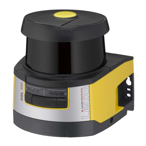
Leuze electronic RSL 430 Original Operating Instructions (127 pages)
Safety Laser Scanner
Brand:
Leuze electronic
| Category:
Security Sensors
| Size: 15 MB
Table of Contents
Table of Contents
3
1 About this Document
7
Other Applicable Documents
7
Downloading Configuration Software from the Internet
7
Used Symbols and Signal Words
7
Checklists
8
2 Safety
9
Intended Use
9
Vapors, Smoke, Dust, Particles
10
Stray Light
10
Obstructions in the Protective Field
10
Foreseeable Misuse
11
Competent Persons
11
Disclaimer
12
Laser Safety Notices - Laser Class 1 for Wavelength Range Outside 400 - 700 Nm
12
Responsibility for Safety
12
3 Device Description
13
Device Overview
14
Protective Function of RSL 400 Safety Sensors
15
Parameters for Protective Function
15
Device and Monitoring Functions
15
USB Connection
16
Connection Unit
16
Display Elements
17
LED Indicator
17
Alphanumerical Display
17
Field-Of-View Display
19
Mounting System (Optional)
19
Loop Guard (Optional)
19
4 Configuration and Diagnostic Software Sensor Studio
20
System Requirements
20
Installing Software
20
User Interface
22
FDT Frame Menu
23
Project Wizard
23
DTM Change
24
User Management
24
Exiting Sensor Studio
24
Using Configuration Projects
25
Selecting Access Level
27
Identification
28
Process
28
Configuration
28
Diagnosis
28
Settings
29
5 Functions
31
Authorization Concept of Safety Sensor
31
Function Modes of Safety Sensor
32
One Protective Function
33
Two Protective Functions
33
One Protective Function - Four Field Mode
33
Selectable Resolution for Hand, Leg and Body Detection
35
Speed-Dependent Protective Function for Vehicles
35
Response Time
35
Configurable Start-Up Behavior
35
Automatic Start/Restart
35
Start Interlock/Automatic Restart
36
Start/Restart Interlock (RES)
36
Field Pair Changeover
37
Fixed Selection of One Field Pair
37
Changeover of Five Field Pairs in Changeover Mode Overlapped Monitoring
38
Changeover of Ten Field Pairs in Changeover Mode Fixed Changeover Moment
39
Changeover of 2X Ten Field Pairs
40
Monitoring of Field Pair Changeover
40
Reference Contour Monitoring
41
Field Pair Monitoring
41
Internal Safe Time Delay
41
EDM Contactor Monitoring
41
E-Stop Linkage
42
5.13.1 Contact-Based Safety Circuit
42
5.13.2 Linkage of Electronic Safety-Related Switching Outputs
43
Signaling Functions
43
6 Applications
44
Stationary Danger Zone Guarding
44
Stationary Point of Operation Guarding
45
Stationary Access Guarding
46
Mobile Danger Zone Guarding
47
Danger Zone Safeguarding on Side-Tracking Skates
49
7 Mounting
50
Basic Infos
50
Calculation of Safety Distance S
50
Suitable Mounting Locations
51
Mounting the Safety Sensor
51
Mounting Examples
54
Information on Protective Field Dimensioning
55
Stationary Danger Zone Guarding
58
Stationary Point of Operation Guarding
61
Stationary Access Guarding
62
Mobile Danger Zone Guarding on Agvs
63
Minimum Distance D
64
Protective Field Dimensions
65
Mobile Side Guarding on Agvs
66
Mounting Accessories
66
Mounting System
66
Loop Guard
67
8 Electrical Connection
68
Electrical Supply
69
Interfaces
69
Connection Cable, Control
70
Connection Cable with M30 Connector
71
Pin Assignment of M12 Ethernet Interface (Communication) ( D-Coded)
72
Connection Unit CU429
73
Circuit Diagram Example
75
9 Configuring the Safety Sensor
76
Defining Safety Configuration
76
Connecting Safety Sensor to PC
78
Connection Via Ethernet Cable
78
Connection Via Bluetooth
78
Connection Via USB
78
Communication between Safety Sensor and PC
79
Determine the Configuration Project
80
Configuring Protective Function
81
Creating Simple Safety Configuration
81
Entering Administration Parameters
81
Activating Protective Function and Contactor Monitoring
81
Creating and Configuring Protective/Warning Field Pairs
82
Configuring Field Pair Monitoring
84
Defining Permissible Field Pair Changeovers
85
Configuring Signal Outputs
85
Saving Configuration
86
Transferring Configuration Project to Safety Sensor
86
Selecting Access Level
88
Reset Safety Configuration
88
10 Starting up the Device
89
Switching on
89
Aligning the Safety Sensor
89
Unlocking Start/Restart Interlock
89
Shutting down
90
Restarting
90
Starting up Replacement Scanner Unit
90
11 Testing
92
Before the Initial Start-Up and Following Modifications
92
11.1.1 Checklist for Integrator - to be Performed Prior to the Initial Start-Up and Following Modifications
92
To be Performed Periodically by Competent Persons
94
Periodically by the Operator
94
11.3.1 Checklist - Periodically by the Operator
95
12 Diagnostics and Troubleshooting
96
What to Do in Case of Failure
96
Diagnostics Displays
96
13 Care, Maintenance and Disposal
100
Changing Scanner Unit
100
Cleaning the Optics Cover
101
Servicing
102
Disposing
102
14 Service and Support
103
15 Technical Data
104
General Specifications
104
Dimensions
109
Dimensioned Drawings: Accessories
111
Representation of Safety Sensor Status
119
16 Standards and Legal Regulations
123
17 Order Guide and Accessories
124
18 EC Declaration of Conformity
127
Advertisement
Advertisement
Related Products
Leuze electronic RSL 410
Leuze electronic RSL 420
Leuze electronic RSL 425
Leuze electronic RSL 440
Leuze electronic RSL 445
Leuze electronic RSL 450P
Leuze electronic RSL 455P
Leuze electronic RSL 420P
Leuze electronic RS4
Leuze electronic RS 485
Leuze electronic Categories
Accessories
Barcode Reader
Measuring Instruments
Security Sensors
Scanner
More Leuze electronic Manuals
Login
Sign In
OR
Sign in with Facebook
Sign in with Google
Upload manual
Upload from disk
Upload from URL