Sign In
Upload
Manuals
Brands
Lenze Manuals
Control Unit
L-force 9400 Series
Lenze L-force 9400 Series Manuals
Manuals and User Guides for Lenze L-force 9400 Series. We have
10
Lenze L-force 9400 Series manuals available for free PDF download: Hardware Manual, Software Manual, Mounting Instructions, Commissioning Manual, Manual
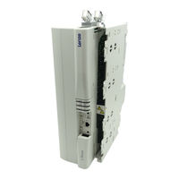
Lenze L-force 9400 Series Hardware Manual (583 pages)
Brand:
Lenze
| Category:
Servo Drives
| Size: 19 MB
Table of Contents
Table of Contents
3
1 Preface
9
The 9400 Servo Drives Product Range
9
Features
9
System Overview
9
The System
9
About this Hardware Manual
9
Information Provided by the Hardware Manual
9
Products to Which the Hardware Manual Applies
9
Legal Regulations
17
2 Guide
19
Terms and Abbreviations Used
19
Total Index
22
3 Safety Instructions
27
General Safety and Application Notes for Lenze Controllers
27
General Safety and Application Instructions for Lenze Motors
27
Residual Hazards
35
Notes Used
36
Single-Axis Controllers
37
Device Features
38
Single-Axis Controllers
38
General Data and Operating Conditions
39
Rated Data (Devices for 400/500V Mains)
47
Overview
47
Operation at Rated Mains Voltage 230 V
50
Operation at Rated Mains Voltage 400 V
50
Operation at Rated Mains Voltage 500 V
50
Fuses and Cable Cross-Sections
66
Overcurrent Operation
68
Current-Time Diagrams
75
Device Description
85
Devices in the Range 2
86
Devices in the Range 32
88
Devices in the Range 145
90
Mechanical Installation
92
Important Notes
92
Devices in the Range 2
92
Devices in the Range 32
95
Devices in the Range 145
95
Devices in the Range 460
97
Important Notes
98
Wiring
98
Safety Notes for the Installation According to UL or UR
100
Earthing of Internal EMC Filters
103
Earthing of Internal EMC Filters
104
Devices in the Range 2
107
Devices in the Range 32
116
Devices in the Range 145
121
Control Terminals
138
Connecting Busbars
213
Design of the Cables
213
How to Connect the Shield
261
Terminal Assignment
261
Wiring of Control Connections
300
Communication Modules
305
Memory Modules
306
Safety Modules
307
Final Works
308
Further Settings
308
Initial Commissioning on 230 V or 500 V Mains Voltage
308
Initial Commissioning on 400 V Mains Voltage
308
DC-Bus Operation
309
Introduction
309
Terminology and Abbreviations Used
310
Comparison Single-Axis Controllers / Multi-Axis Controllers
311
Advantages of a Drive System
312
General Information on the Accessories
313
Conditions for Trouble-Free DC-Bus Operation
314
Number of Feeding Points
314
Other Conditions
314
Voltages
314
DC-Bus Variants
315
Supply from a Supply Module
315
Supply from Controllers
316
General Data
317
Rated Data
317
DC-Supply Power
319
DC-Power Requirements
323
DC Fuses
325
Accessories for Diagnostics
339
Hand-Held Terminal
339
Keypad
339
USB Diagnostic Adapter
339
Components for Operation in the DC-Bus Connection
339
DC-Feeding Point
339
GG1 Busbar Mounting Set
339
GG2 Busbar Mounting Set
339
GG3 Busbar Mounting Set
339
Filters
340
Mains Filters for Power Supply Modules
340
Mains Filters for Regenerative Power Supply Modules
340
Mains Filters for Single-Axis Controllers
340
RFI Filters for Power Supply Modules
340
RFI Filters for Single-Axis Controllers
340
Sinusoidal Filter 115
340
Sinusoidal Filter 180
340
Sinusoidal Filter 23.5
340
Sinusoidal Filters 4
340
Advertisement
Lenze L-force 9400 Series Software Manual (360 pages)
Regenerative power supply module
Brand:
Lenze
| Category:
Servo Drives
| Size: 2 MB
Table of Contents
Table of Contents
3
1 About this Documentation
9
Conventions Used
10
Terminology Used
10
Definition of Notes Used
11
2 Commissioning
12
Short Setup
13
Example Circuit
13
Keypad
14
Commissioning with the Engineer
15
Controlling the Regenerative Power Supply Module Via Terminals
19
Device Replacement
20
Filter Replacement
20
3 Regenerative Power Supply Module Application
21
Parameterising the Brake Chopper/Brake Resistor
22
Setting the Voltage Threshold for Braking Operation
24
Setting the Brake Chopper Mode
24
Monitoring
25
Overcurrent Protection
25
Transistor
26
I2T Utilisation of Brake Resistor
27
DC-Bus Overvoltage
29
Signal Configuration
30
Device and Line Interface
30
Output Ports
31
Assignment of the I/O Terminals
34
4 Device Interface
36
Device Commands
37
Load Lenze Setting
39
Load Start Parameters
40
Load Route Data from the ENP
41
Activate Application
42
Save Selected Application
43
Save Start Parameters
44
Delete Logbook
46
Archive Log File
47
Start Application
48
Stop Application
49
Reset Program
50
Delete Program
51
Restart Program
52
Reset Runtime Measurement
53
Inhibit Controller
55
Enable Controller
56
Reset Error
57
Reset Max DC Power Mot
58
Reset Max DC Power Reg
59
Reset Max. Line Power Reg
60
Reset Transmitted Energy
61
Reset Regenerated Energy
62
CAN On-Board: Reset Node
63
CAN Module: Reset Node
64
CAN On-Board: Pred.connect.set
65
CAN Module: Pred.connect.set
66
CAN On-Board: Identify Node
67
CAN Module: Identify Node
68
Unbind/Bind Ethernet Module MXI1
69
Unbind/Bind Ethernet Module MXI2
69
Format File System
75
Restore File System
75
Prepare Firmware Update
77
Restart Controller
78
Device States
79
State "Initialisation Active
80
State "Device Is Ready to Switch on
81
State "Device Is Switched on
81
State "Operation
82
State "Warning Active
82
State "Warning Locked Active
82
State "Trouble Active
82
State "Fault Active
83
State "System Fault Active
83
Automatic Restart after Power-On/Trouble/Fault
84
Monitoring the Device Utilisation
86
Display of Peak Power
87
Display of Output and Regenerated Energy
88
5 O Terminals
89
Overview
89
Analog Inputs
90
Terminal Assignment/Electrical Data
90
Parameter Setting
91
Reconfiguring Analog Input 1 into Current Input
91
Analog Outputs
92
Terminal Assignment/Electrical Data
92
Parameter Setting
93
Digital Inputs
94
Terminal Assignment/Electrical Data
94
Parameter Setting
94
Digital Outputs
95
Terminal Assignment/Electrical Data
95
Parameter Setting
95
State Bus" Monitoring Function
96
6 "CAN on Board" System Bus
97
General Information
98
General Data and Operating Conditions
99
Supported Protocols
99
Communication Time
100
Possible Settings Via DIP Switches
101
Address
101
Setting the Baud Rate
102
LED Status Displays for the System Bus
103
Structure of the CAN Data Telegram
104
Identifier
104
User Data
106
Communication Phases/Network
107
Management
107
Network Management Telegram (NMT)
109
Parameterising a Device to Act as a CAN Master
110
Process Data Transfer
111
Process Data Object Identifiers
112
Transmission Type
113
Masking of Tpdos for Event Control
114
Data Reception Monitoring of Rpdos
114
Synchronisation of Pdos Via Sync Telegram
115
Parameter Setting
116
Position
117
Parameter Data Transfer
120
Parameter Data Object Identifiers
121
User Data
122
Command
123
Addressing by Means of Index and Subindex
124
Data 1
125
Error Messages
126
Examples
126
Read Parameters
128
Write Parameters
129
Read Block Parameters
130
Diagnostics
133
Monitoring
134
Node Guarding Protocol
134
Telegram Structure
135
Parameter Setting
136
Commissioning Example
138
Heartbeat Protocol
140
Telegram Structure
141
Parameter Setting
141
Commissioning Example
143
Emergency Telegram
144
Implemented Canopen Objects
145
7 Oscilloscope
170
Technical Data
170
Function Description
171
User Interface
172
Oscilloscope Toolbar
173
Oscillograph
173
Vertical Settings
173
Status Bar
174
Trigger/Cursor Settings
174
Horizontal Settings
174
Recording Settings
174
Operation
175
Recorded
175
Selecting the Recording Time/Sample Rate
176
Selecting the Trigger Condition
177
Starting Recording
178
Adjusting the Representation
179
Reading Individual Measured Values
180
Data Records
181
Record
181
Loading/Importing a Data Record
183
Deleting a Data Record in the Project
184
Overlay Function
184
Copying a Data Record to the Clipboard
185
Internal Variables
186
Signals)
186
8 Diagnostics & Fault Analysis
187
LED Status Displays
187
LED Status Displays for the Device State
188
Drive Diagnostics with the »Engineer
189
Device Diagnostics Via Keypad/Bus
190
System
190
Logbook
192
Entries
192
Functional Description
193
Filtering Logbook Entries
193
Exporting Logbook Entries to a File
195
Monitoring
196
Response
196
Warning Thresholds
197
Lenze L-force 9400 Series Hardware Manual (269 pages)
Brand:
Lenze
| Category:
Servo Drives
| Size: 7 MB
Table of Contents
Preface 1
3
The 9400 Servo Drives Product Range
5
Information Provided by the Hardware Manual
7
Products to Which the Hardware Manual Applies
8
Legal Regulations
13
4 Single-Axis Controllers
33
Table of Contents
33
Device Features
35
General Data and Operating Conditions
37
Rated Data (Devices for 400/500V Mains)
43
Overview
43
Operation at Rated Mains Voltage 230 V
46
Operation at Rated Mains Voltage 400 V
48
Operation at Rated Mains Voltage 500 V
52
Fuses and Cable Cross-Sections
56
Overcurrent Operation
58
Device Description
61
Devices in the Range 2
62
Devices in the Range 32
64
Devices in the Range 145
66
Devices in the Range 2
66
Devices in the Range 32
66
Devices in the Range 460
69
Wiring
89
Devices in the Range 2
89
Devices in the Range 32
90
Devices in the Range 145
100
Control Terminals
121
Multi-Axis Controllers 5
137
Device Features
139
General Data and Operating Conditions
141
Rated Data
147
Overview
147
Devices for 400/500V-Mains
149
Overcurrent Operation
152
Mechanical Installation
155
Devices in the Range 2
159
Wiring
161
Important Notes
161
6 DC Power Supply Module
193
Safety Notes for the Installation According to UL or
193
Device Features
195
General Data and Operating Conditions
197
Rated Data (Devices for 400/500V Mains)
199
Fuses and Cable Cross-Sections
209
Device Description
211
Devices in the Range 10
212
Devices in the Range 100
214
Devices in the Range 10
214
Devices in the Range 100
215
Connecting Busbars
229
Terminal Assignment
231
Control Terminals
237
Final Works
241
DC-Bus Operation 7
243
Introduction
245
Terminology and Abbreviations Used
245
Comparison Single-Axis Controllers / Multi-Axis Controllers
246
Advantages of a Drive System
247
General Information on the Accessories
248
Conditions for a Trouble-Free Network of Several Drives
249
Voltages
249
Number of Feeding Points
249
Other Conditions
249
DC-Bus Variants
251
Supply from a Supply Module
251
Supply from Controllers
252
Rated Data
253
General Data
253
DC-Supply Power
254
DC-Power Requirements
257
Basic Dimensioning
259
General Information
259
Power Distribution of Controllers
261
Motor Efficiency
261
Power Loss of Devices
261
Determining the Power Requirements
262
Determining the Regenerative Power Requirements
262
Cable Protection
263
Filters
264
Cables
264
Braking Operation in a Drive System
265
Basic Considerations
265
Advertisement
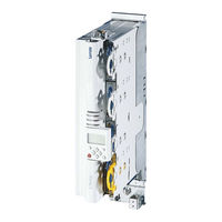
Lenze L-force 9400 Series Mounting Instructions (192 pages)
Single Drive Axis module
Brand:
Lenze
| Category:
Control Unit
| Size: 7 MB
Table of Contents
Deutsch
5
Table of Contents
5
1 Schnelleinstieg
6
2 Sicherheitshinweise
7
Allgemeine Sicherheits− und Anwendungshinweise für Lenze−Antriebsregler
7
Restgefahren
10
Verwendete Hinweise
11
Sicherheitshinweise für die Installation nach UL/CSA
12
3 Technische Daten
13
Allgemeine Daten und Einsatzbedingungen
13
Elektrische Daten
15
Abmessungen
17
4 Schaltungsbeispiel
18
5 Montagesockel Montieren und Verdrahten
19
6 Grundgerät Montieren
20
7 Grundgerät Verdrahten
21
8 Gerätemodule Verdrahten
27
Kommunikationsmodule
27
Funktionsmodule
28
Speichermodule
30
Sicherheitsmodule
32
9 Abschließende Arbeiten
39
Inbetriebnahme Vorbereiten
39
English
41
1 Quick Start Guide
42
2 Safety Instructions
43
General Safety and Application Notes for Lenze Controllers
43
Residual Hazards
46
Notes Used
47
Safety Instructions for the Installation According to UL/CSA
48
3 Technical Data
49
General Data and Operating Conditions
49
Electrical Data
51
Dimensions
53
4 Example Circuit
54
5 Mounting and Wiring the Installation Backplane
55
6 Mounting the Standard Device
56
7 Wiring of the Standard Device
57
8 Wiring the Device Modules
63
Communication Modules
63
Function Modules
64
Memory Modules
66
Safety Modules
68
9 Final Works
75
Preparing the Commissioning Procedure
75
Français
77
1 Prise en Main Rapide
78
2 Consignes de Sécurité
79
Consignes Générales de Sécurité Et D'utilisation Relatives Aux Variateurs Lenze
79
Dangers Résiduels
82
Consignes Utilisées
83
Consignes de Sécurité Pour L'installation Selon UL / CSA
84
3 Spécifications Techniques
86
Caractéristiques Générales Et Conditions D'utilisation
86
Caractéristiques Électriques
89
Encombrements
91
4 Exemple de Câblage
92
5 Montage Et Câblage du Socle de Montage
93
6 Montage de L'appareil de Base
94
7 Câblage de L'appareil de Base
95
8 Câblage des Modules
101
Modules de Communication
101
Modules de Fonction
102
Modules de Mémoire
104
Modules de Sécurité
106
9 Fin du Montage
114
Préparatifs À la Mise en Service
114
Español
117
1 Guía Rápida
118
2 Instrucciones de Seguridad
119
Instrucciones de Seguridad y Uso para Convertidores Lenze
119
Peligros Residuales
122
Indicaciones Utilizadas
123
Instrucciones de Seguridad para la Instalación Según UL/CSA
124
3 Datos Técnicos
125
Datos Generales y Condiciones de Uso
125
Datos Eléctricos
127
Dimensiones
129
4 Ejemplo de Conexión
130
5 Montar y Cablear Base de Montaje
131
6 Montar Equipo Básico
132
7 Cablear Equipo Básico
133
8 Cablear Módulos del Equipo
139
Módulos de Comunicación
139
Módulos de Función
140
Módulos de Memoria
142
Módulos de Seguridad
144
9 Últimos Pasos
152
Preparar Puesta en Marcha
152
Italiano
155
1 Guida Rapida
156
2 Informazioni Sulla Sicurezza
157
Norme Generali DI Utilizzo E DI Sicurezza Per Unità DI Controllo Lenze
157
Altri Pericoli
160
Avvertenze Utilizzate
161
Informazioni Sulla Sicurezza Per L'installazione Secondo UL/CSA
162
3 Dati Tecnici
163
Dati Generali E Condizioni DI Impiego
163
Dati Elettrici
165
Dimensioni
167
4 Esempio DI Schema DI Collegamento
168
5 Installazione E Cablaggio Della Base DI Montaggio
169
6 Montaggio del Modulo Asse
170
7 Cablaggio del Modulo Asse
171
8 Cablaggio Dei Moduli Aggiuntivi
177
Moduli DI Comunicazione
177
Moduli Funzione
178
Moduli DI Memoria
180
Moduli DI Sicurezza
182
9 Operazioni Conclusive
189
Preparazione Alla Messa in Servizio
189
Lenze L-force 9400 Series Mounting Instructions (148 pages)
RFI filter
Brand:
Lenze
| Category:
Water Filtration Systems
| Size: 1 MB
Table of Contents
Deutsch
3
Table of Contents
3
1 Über diese Dokumentation
4
Informationen zur Gültigkeit
4
Zielgruppe
4
Dokumenthistorie
5
Verwendete Konventionen
5
Verwendete Hinweise
6
2 Sicherheitshinweise
8
Allgemeine Sicherheitshinweise
8
Restgefahren
9
3 Produktbeschreibung
11
Lieferumfang
11
Übersicht
11
Identifikation
12
Einsatzbedingungen
12
4 Technische Daten
13
Allgemeine Daten und Einsatzbedingungen
13
Bemessungsdaten
15
Mechanische Daten
16
5 Mechanische Installation
18
Wichtige Hinweise
18
Anordnung der Geräte
19
Befestigungsraster
21
Montageschritte
22
6 Elektrische Installation
24
Wichtige Hinweise
24
Anschlussplan
26
Anschlussdaten
28
Montageschritte
29
English
32
1 About this Documentation
33
Validity Information
33
Target Group
33
Document History
33
Conventions Used
34
Notes Used
35
2 Safety Instructions
37
General Safety Information
37
Residual Hazards
38
3 Product Description
40
Scope of Supply
40
Overview
40
Identification
41
Operating Conditions
41
4 Technical Data
42
General Data and Operating Conditions
42
Rated Data
44
Mechanical Data
45
5 Mechanical Installation
47
Important Notes
47
Arrangement of the Devices
48
Mounting Grid
50
Mounting Steps
51
6 Electrical Installation
53
Important Notes
53
Connection Plan
55
Connection Data
57
Mounting Steps
58
Français
61
1 Présentation du Document
62
Validité
62
Public Visé
62
Historique du Document
62
Conventions Utilisées
63
Consignes Utilisées
64
2 Consignes de Sécurité
66
Consignes Générales de Sécurité
66
Dangers Résiduels
67
3 Description du Produit
69
Equipement Livré
69
Présentation Générale
69
Identification
70
Conditions D'utilisation
70
4 Spécifications Techniques
71
Caractéristiques Générales Et Conditions D'utilisation
71
Caractéristiques Assignées
73
Caractéristiques Mécaniques
74
5 Installation Mécanique
76
Remarques Importantes
76
Disposition des Appareils
77
Grille de Fixation
79
Opérations de Montage
80
6 Installation Électrique
82
Remarques Importantes
82
Schéma de Câblage
84
Données de Raccordement
86
Opérations de Montage
87
Español
89
1 Acerca de Esta Documentación
90
Información sobre la Validez
90
Grupo Objetivo
90
Historia del Documento
90
Convenciones Utilizadas
91
Indicaciones Utilizadas
92
2 Instrucciones de Seguridad
93
Instrucciones Generales de Seguridad
93
Peligros Residuales
94
3 Descripción del Producto
96
Alcance del Suministro
96
Vista General
96
Identificación
97
Condiciones de Uso
97
4 Datos Técnicos
98
Datos Generales y Condiciones de Uso
98
Datos Nominales
100
Datos Mecánicos
101
5 Instalación Mecánica
103
Indicaciones Importantes
103
Colocación de Los Equipos
104
Plantilla de Sujeción
106
Pasos para el Montaje
107
6 Instalación Eléctrica
109
Indicaciones Importantes
109
Esquema de Conexiones
111
Datos de Conexión
113
Pasos para el Montaje
114
Italiano
117
1 Informazioni Sul Manuale
118
Informazioni Sulla Validità
118
A Chi È Rivolto
118
Cronologia del Documento
118
Convenzioni Utilizzate
119
Avvertenze Utilizzate
120
2 Informazioni Sulla Sicurezza
122
Note Generali DI Sicurezza
122
Altri Pericoli
123
3 Descrizione del Prodotto
125
Oggetto Della Fornitura
125
Panoramica
125
Identificazione
126
Condizioni DI Utilizzo
126
4 Dati Tecnici
127
Dati Generali E Condizioni DI Impiego
127
Dati Nominali
129
Dati Meccanici
130
5 Installazione Meccanica
132
Note Importanti
132
Disposizione Delle Apparecchiature
133
Griglia DI Fissaggio
135
Procedura DI Montaggio
136
6 Installazione Elettrica
138
Note Importanti
138
Schema DI Collegamento
140
Dati DI Collegamento
142
Procedura DI Montaggio
143
Lenze L-force 9400 Series Commissioning Manual (108 pages)
Single & Multi Drive HighLine Axis module
Brand:
Lenze
| Category:
Servo Drives
| Size: 0 MB
Table of Contents
Deutsch
3
Table of Contents
3
1 Über diese Dokumentation
4
Verwendete Konventionen
4
Definition der Verwendeten Hinweise
5
2 Sicherheitshinweise
6
3 Basis-Inbetriebnahme
8
4 Erweiterte Inbetriebnahme
10
Motor und Antriebsregler Aufeinander Abstimmen
10
Antriebsgrundfunktionen
12
5 Klemmenbelegung der Technologieapplikationen
15
Stellantrieb - Drehzahl
15
Stellantrieb - Drehmoment
15
Positionier-Ablaufsteuerung/Tabellenpositionierung
16
Elektronisches Getriebe/Gleichlauf
16
Geräteprofil Cia402 (Ab Softwarestand V7)
17
6 Hinweise für Bestimmte Anwendungen
18
Hubwerk/Heber
18
Lüfter bei Sensorlosen Betriebsarten
18
7 Diagnose
20
English
23
1 About this Documentation
24
Conventions Used
24
Definition of Notes Used
25
2 Safety Instructions
26
3 Basic Commissioning
27
4 Extended Commissioning
29
Adjust Motor and Controller to each Other
29
Basic Drive Functions
31
5 Terminal Assignment of the Technology Applications
34
Actuating Drive - Speed
34
Actuating Drive - Torque
34
Positioning Sequence Control/Table Positioning
35
Electronic Gearbox/Synchronism
35
Device Profile Cia402 (from Software Version V7)
36
6 Notes on Special Applications
37
Hoist/Lifter
37
Fan in Sensorless Operating Modes
37
7 Diagnostics
39
Français
43
1 Propos de Cette Documentation
44
Conventions Utilisées
44
Définition des Consignes Utilisées
45
2 Consignes de Sécurité
46
3 Mise en Service Standard
48
4 Mise en Service Avancée
50
Adaptation du Moteur Et du Variateur
50
Fonctions D'entraînement de Base
53
5 Affectation des Bornes des Applications Technologiques
56
Actionneur - Vitesse
56
Actionneur - Couple
56
Commande Séquentielle de Positionnement / Positionnement Par Tableaux
57
Réducteur Électronique / Fonctionnement Synchrone
57
Profil D'appareil Cia402 (À Partir de la Version Logicielle V7)
58
6 Remarques Relatives À des Applications Spécifiques
59
Engin de Levage / Élévateur
59
Applications Avec Ventilateurs Fonctionnant en Mode Sans Bouclage
59
7 Diagnostic
61
Español
65
1 Acerca de Esta Documentación
66
Convenciones Utilizadas
66
Definición de las Notas Utilizadas
67
2 Instrucciones de Seguridad
68
3 Puesta en Marcha Básica
70
4 Puesta en Marcha Ampliada
72
Adaptar el Motor al Convertidor
72
Funciones Básicas del Accionamiento
75
5 Asignación de Bornes para las Aplicaciones Tecnológicas
78
Actuador - Velocidad
78
Actuador - Par
78
Control de Secuencia de Posicionamiento/Posicionamiento de Tablas
79
Reductor Electrónico/Sincronismo
79
Perfil del Equipo Cia402 (a Partir de la Versión de Software V7)
80
6 Instrucciones para Determinadas Aplicaciones
81
Mecanismo de Elevación/Elevador
81
Ventilador en Los Modos de Funcionamiento Sensorless
81
7 Diagnóstico
83
Italiano
87
1 Informazioni Sulla Presente Documentazione
88
Convenzioni Utilizzate
88
Simbologia Delle Note E Avvertenze Utilizzate
89
2 Note DI Sicurezza
90
3 Messa in Servizio DI Base
92
4 Messa in Servizio Avanzata
94
Adattamento del Motore All'unità DI Controllo
94
Funzioni DI Base
97
5 Assegnazione Dei Morsetti Delle Applicazioni Tecnologiche
100
Attuatore DI Velocità
100
Attuatore DI Coppia
100
Posizionamento con Controllo Sequenziale/Posizionamento Tabellare
101
Riduttore Elettronico/Sincronismo
101
Profilo DI Azionamento Cia402 (da Versione Software V7)
102
6 Avvertenze Per Determinate Applicazioni
103
Sistemi DI Sollevamento
103
Ventilatori in Modi Operativi Sensorless
103
7 Diagnostica
105
Lenze L-force 9400 Series Mounting Instructions (104 pages)
Motor brake control
Brand:
Lenze
| Category:
Servo Drives
| Size: 0 MB
Table of Contents
Deutsch
5
Table of Contents
5
1 Sicherheitshinweise
7
Definition der Verwendeten Hinweise
7
Allgemeine Sicherheits− und Anwendungshinweise
9
Sicherheitshinweise für die Installation nach UL oder UR
10
2 Technische Daten
11
Allgemeine Daten und Einsatzbedingungen
11
Bemessungsdaten
15
Mechanische Daten
17
3 Mechanische Installation
18
4 Elektrische Installation
19
Wichtige Hinweise
19
Anschlussdaten
20
Verdrahtungsbeispiel
22
English
25
1 Safety Instructions
27
Definition of Notes Used
27
General Safety and Application Notes
29
Safety Instructions for the Installation According to UL or UR
30
2 Technical Data
31
General Data and Operating Conditions
31
Rated Data
35
Mechanical Data
37
3 Mechanical Installation
38
4 Electrical Installation
39
Important Notes
39
Connection Data
40
Wiring Example
42
Français
45
1 Consignes de Sécurité
47
Définition des Conventions Utilisées
47
Instructions Générales de Sécurité Et D'utilisation
49
Consignes de Sécurité Pour L'installation Selon UL Ou UR
50
2 Spécifications Techniques
51
Caractéristiques Générales Et Conditions D'utilisation
51
Caractéristiques Nominales
55
Caractéristiques Mécaniques
57
3 Installation Mécanique
58
4 Installation Électrique
59
Remarques Importantes
59
Données de Raccordement
60
Exemple de Câblage
62
Español
65
1 Instrucciones de Seguridad
67
Definición de las Instrucciones Utilizadas
67
Instrucciones Generales de Seguridad y de Uso
69
Instrucciones de Seguridad para la Instalación Según UL O UR
70
2 Datos Técnicos
71
Datos Generales y Condiciones de Uso
71
Datos Nominales
75
Datos Mecánicos
77
3 Instalación Mecánica
78
4 Instalación Eléctrica
79
Indicaciones Importantes
79
Datos de Conexión
80
Ejemplo de Cableado
82
Italiano
85
1 Informazioni Sulla Sicurezza
87
Simbologia Delle Note E Avvertenze Utilizzate
87
Note Generali DI Sicurezza E Utilizzo
89
Informazioni Sulla Sicurezza Per L'installazione Secondo la Normativa UL O UR
90
2 Dati Tecnici
91
Dati Generali/Condizioni DI Utilizzo
91
Dati Nominali
95
Dimensioni
97
3 Installazione Meccanica
98
4 Installazione Elettrica
99
Note Importanti
99
Dati DI Collegamento
100
Esempio DI Cablaggio
102
Lenze L-force 9400 Series Manual (68 pages)
Ethernet communication module
Brand:
Lenze
| Category:
Control Unit
| Size: 1 MB
Table of Contents
Table of Contents
3
1 About this Documentation
5
Document History
7
Conventions Used
8
Terminology Used
9
Notes Used
10
2 Safety Instructions
11
General Safety Instructions and Application
11
Notes
11
Device and Application-Specific Safety Instructions
12
Residual Hazards
12
3 Product Description
13
Application as Directed
13
Identification
13
Product Features
14
Terminals and Interfaces
14
4 Technical Data
15
General Data and Operating Conditions
15
Protective Insulation
16
Dimensions
18
5 Installation
19
Mechanical Installation
20
Assembly
20
Disassembly
20
Electrical Installation
21
EMC-Compliant Wiring
21
Ethernet Connection
22
Specification of the Ethernet
22
Cable
23
Voltage Supply
25
6 Commissioning
26
Before Initial Switch-On
26
Configuring the Communication Module
27
Setting the Address
28
Address
29
IP Address
31
Subnet Mask
31
Gateway Address
32
Mac-ID
32
DHCP Implementation in the Servo Drive 9400
34
Basic Terms
34
DHCP Network Architecture
35
DHCP Operating Mode
35
DHCP Packet Structure
36
Initial Switch-On
37
7 Parameter Data Transfer
38
Structure of the Ethernet Data Telegram
39
Reading Parameters from the Controller
40
Writing Parameters to the Controller
40
Assignment of User Data Areas P0
41
Transmission Abort
42
Error Codes
43
Telegram Examples
45
Example 1: Querying the Heatsink Temperature (Read Request)
45
Example 2: Querying the Firmware Product Type (Read Request)
47
Example 3: Setting the Deceleration Time for Quick Stop (QSP) (Write Request)
49
8 Diagnostics
51
LED Status Displays
52
Error Messages of the Servo Drive 9400
53
9 Parameter Reference
54
Parameters of the Standard Device that Are Relevant to Communication
54
Parameters of the Communication Module for Slot MXI1
56
Parameters of the Communication Module for Slot MXI2
60
Table of Attributes
64
10 Index
66
Lenze L-force 9400 Series Mounting Instructions (62 pages)
Regenerative power supply module
Brand:
Lenze
| Category:
DC Drives
| Size: 2 MB
Table of Contents
Table of Contents
33
1 About this Documentation
34
Validity Information
34
Document History
34
Target Group
34
Conventions Used
34
Notes Used
35
2 Safety Instructions
36
General Safety and Application Notes for Lenze Power Supply Modules
36
Residual Hazards
38
Safety Instructions for the Installation According to UL oder UR
39
3 Technical Data
40
General Data and Operating Conditions
40
Electrical Data
42
Fuses and Cable Cross−Sections
44
Mechanical Data
45
4 Mounting and Wiring the Installation Backplane
46
5 Mounting the Standard Device
47
6 Wiring of the Standard Device
48
7 Wiring the Device Modules
52
Communication Modules
52
Memory Modules
58
Safety Modules
59
8 Final Works
60
Initial Commissioning at a Mains Voltage of 400 V
60
Initial Commissioning at a Mains Voltage of 230 or 500 V
60
Further Settings
61
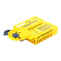
Lenze L-force 9400 Series Manual (19 pages)
Safety module, L-Force 9400
Brand:
Lenze
| Category:
Control Unit
| Size: 0 MB
Table of Contents
Table of Contents
3
Safety Engineering
4
Basics
4
Introduction
4
Drive−Based Safety with L−Force | 9400
4
Terms and Abbreviations of the Safety Engineering
5
Important Notes
6
Safety Instructions
7
Hazard and Risk Analysis
9
Standards
9
Safety Notes for the Installation According to UL or UR
9
Overview of Sensors
9
Device Modules
11
Slot
11
Function Mode of the Safety Modules
12
Safety Module SM0
13
Safety Module SM100
14
Acceptance
19
Description
19
Periodic Inspections
19
Advertisement
Related Products
Lenze L-force PROFIBUS-DP
Lenze L-force PROFIBUS-DP PT
Lenze L-force Communication LECOM-B
Lenze L-force Communication LECOM-LI
Lenze L-force E94ASHE0024
Lenze L-force E94ASHE0074
Lenze L-force E94ASHE0134
Lenze L-force E94ASHE0174
Lenze L-force E94ASHE0244
Lenze L-force E94ASHE0044
Lenze Categories
DC Drives
Control Unit
Inverter
Engine
Controller
More Lenze Manuals
Login
Sign In
OR
Sign in with Facebook
Sign in with Google
Upload manual
Upload from disk
Upload from URL