Sign In
Upload
Manuals
Brands
Lenze Manuals
Control Unit
ECSCA Series
Lenze ECSCA Series Manuals
Manuals and User Guides for Lenze ECSCA Series. We have
3
Lenze ECSCA Series manuals available for free PDF download: Operating Instructions Manual, Mounting Instructions
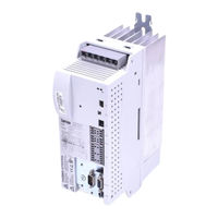
Lenze ECSCA Series Operating Instructions Manual (485 pages)
Axis module - Application
Brand:
Lenze
| Category:
Control Unit
| Size: 25 MB
Table of Contents
Scope of Supply
5
Status Displays
5
Table of Contents
6
Preface and General Information
15
About These Operating Instructions
15
Conventions Used in this Manual
15
Terminology Used
16
Code Descriptions
17
Structure of the System Block Descriptions
18
Features of the Ecsxa Axis Module
19
Scope of Supply
20
Legal Regulations
21
System Block Introduction
22
System Blocks ˘ Principle
22
Node Numbers
23
Access Via System Variables
24
Access Via Absolute Addresses
25
Definition of the Inputs/Outputs
25
Integrate System Blocks into DDS
27
Signal Types and Scaling
28
Safety Instructions
29
General Safety and Application Notes for Lenze Controllers
29
Thermal Motor Monitoring
33
Forced Ventilated or Naturally Ventilated Motors
34
Self−Ventilated Motors
35
Residual Hazards
37
Motor Protection
38
Safety Instructions for the Installation According to UL
39
Notes Used
40
Application Notes
40
Technical Data
41
General Data and Operating Conditions
41
Rated Data
43
Current Characteristics
45
Increased Continuous Current Depending on the Control Factor
45
Device Protection by Current Derating
48
Mechanical Installation
49
Important Notes
49
Mounting with Fixing Rails (Standard Installation)
50
Dimensions
50
Mounting Steps
51
Mounting with Thermal Separation (Push−Through Technique)
52
Dimensions
53
Mounting Steps
55
Mounting in Cold−Plate Design
56
Ambient Conditions
56
Dimensions
57
Mounting Steps
58
Electrical Installation
59
Installation According to EMC (Installation of a Ce−Typical Drive System)
59
General Information
59
Power Terminals
62
Connection to the DC Bus (+UG, −UG)
65
Connection Plan for Mimimum Wiring with Internal Brake Resistor
67
Connection Plan for Mimimum Wiring with External Brake Resistor
69
Motor Connection
71
Motor Holding Brake Connection
72
Connection of an Ecsxk
74
Control Terminals
75
Cable Cross−Sections and Screw−Tightening Torques
78
Digital Inputs and Outputs
79
Analog Input
80
Safe Torque off
81
During Operation
83
Automation Interface (AIF)
90
Wiring of System Bus (CAN)
91
Wiring of the Feedback System
96
Resolver Connection
97
Encoder Connection
98
Digital Frequency Input/Output (Encoder Simulation)
101
Commissioning
103
Before You Start
103
Commissioning Steps (Overview)
104
Carrying out Basic Settings with GDC
105
Loading the Lenze Setting
107
Setting of Mains Data
108
Selecting the Function of the Charging Current Limitation
108
Setting the Voltage Thresholds
109
Entry of Motor Data for Lenze Motors
110
Holding Brake Configuration
112
Setting of the Feedback System for Position and Speed Control
113
Resolver as Position and Speed Encoder
114
Ttl/Sincos Encoder as Position and Speed Encoder
116
Ttl/Sincos Encoder as Position Encoder and Resolver as Speed Encoder
119
Absolute Value Encoder as Position and Speed Encoder
123
Absolute Value Encoder as Position Encoder and Resolver as Speed Encoder
126
Setting the Polarity of Digital Inputs and Outputs
130
Entry of Machine Parameters
131
Controller Enable (CINH = 0)
132
Operation with Motors from Other Manufacturers
133
Entering Motor Data Manually
133
Checking the Direction of Rotation of the Motor Feedback System
136
Adjusting Current Controller
137
Effecting Rotor Position Adjustment
139
Optimising the Drive Behaviour after Start
142
Speed Controller Adjustment
142
Adjustment of Field Controller and Field Weakening Controller
145
Resolver Adjustment
148
Parameter Setting
149
General Information
149
Parameter Setting with "Global Drive Control" (GDC)
150
Parameter Setting with the XT EMZ9371BC Keypad
151
Connecting the Keypad
151
Description of the Display Elements
152
Description of the Function Keys
154
Changing and Saving Parameters
155
System Bus (CAN / CAN−AUX) Configuration
156
Setting the CAN Node Address and Baud Rate
156
Settings Via DIP Switch
157
Node Address Setting
157
Settings Via Codes
159
Individual Addressing
161
Determining the Boot−Up Master for the Drive System
163
Setting the Boot−Up Time/Cycle Time
164
Reset Node
166
Axis Synchronisation (CAN Synchronisation)
167
Monitoring of the Synchronisation (Sync Time Slot)
170
Axis Synchronisation Via CAN
171
Axis Synchronisation Via Terminal X6/DI1
172
Node Guarding
173
CAN Management
175
Mapping Indices to Codes
176
Functional Principle
177
Diagnostics Codes
178
CAN Bus Status (C0359/C2459)
178
CAN Telegram Counter (C0360/2460)
179
CAN Bus Load (C0361/2461)
180
Remote Parameterisation (Gateway Function)
181
Configuring the AIF Interface (X1)
183
CAN Baud Rate
183
CAN Boot up (AIF)
184
Node Address (Node ID)
185
Identifiers of the Process Data Objects
186
Individual Identifier Assignment
187
Display of the Identifier Set
188
Cycle Time (XCAN1_OUT
189
Synchronisation
191
XCAN Sync Response
191
XCAN Sync Identifier
191
XCAN Sync Tx Transmission Cycle
192
Reset Node
192
Monitoring
193
Time Monitoring for XCAN1_IN
193
Bus off
194
Operating Status of AIF Interface
196
Monitoring Functions
197
Fault Responses
198
Overview of Monitoring Functions
199
Configuring Monitoring Functions
203
Monitoring Times for Process Data Input Objects
203
Time−Out Monitoring for Activated Remote Parameterisation
205
Short Circuit Monitoring (OC1)
206
Earth Fault Monitoring (OC2)
206
Motor Temperature Monitoring (OH3, OH7)
207
Heatsink Temperature Monitoring (OH, OH4)
209
Monitoring of Internal Device Temperature (OH1, OH5)
210
Function Monitoring of Thermal Sensors (H10, H11)
211
Current Load of Controller (I X T Monitoring: OC5, OC7)
212
Current Load of Motor (I2 X T Monitoring: OC6, OC8)
215
DC−Bus Voltage Monitoring (OU, LU)
219
Voltage Supply Monitoring − Control Electronics (U15)
222
Motor Phase Failure Monitoring (LP1)
222
Monitoring of the Resolver Cable (Sd2)
223
Motor Temperature Sensor Monitoring (Sd6)
224
Monitoring of the Absolute Value Encoder Initialisation (Sd7)
225
Sin/Cos Signal Monitoring (Sd8)
226
Monitoring of the Speed System Deviation (Nerr)
227
Monitoring of Max. System Speed (NMAX)
228
Monitoring of the Rotor Position Adjustment (PL)
229
Diagnostics
230
Diagnostics with Global Drive Control (GDC)
230
Diagnostics with Global Drive Oscilloscope (GDO)
231
GDO Buttons
232
Diagnostics with the XT EMZ9371BC Keypad
233
Diagnostics with Pcan−View
234
Monitoring of Telegram Traffic on the CAN Bus
234
Setting All CAN Nodes to the "Operational" Status
236
Troubleshooting and Fault Elimination
237
Fault Analysis
237
Malfunction of the Drive
242
Fault Messages
243
Fault Messages Causes and Remedies
247
System Blocks
256
Aif_Io_Management (Node Number 161)
256
System Variables
257
Aif1_Io_Automationinterface (Node Number 41)
260
Inputs_Aif1
260
Aif2_Io_Automationinterface (Node Number 42)
268
Inputs_Aif2
268
Outputs_Aif2
270
Aif3_Io_Automationinterface (Node Number 43)
272
Inputs_Aif3
272
Outputs_Aif3
274
ANALOG1_IO (Node Number 11)
276
Can_Management (Node Number 101)
278
Status Messages
281
CAN3_IO (Node Number 33)
295
Inputs_Can3
298
Outputs_Can3
299
Canaux_Management (Node Number 111)
300
Inputs_Canaux_Management
301
System Variables
301
Outputs_Canaux_Management
301
Executing a Reset Node
302
Define Instant of Transmission for Canaux2_Out/Canaux3_Out
302
Status Messages
303
Canaux1_Io (Node Number 34)
304
Inputs_Canaux1
307
Outputs_Canaux1
308
Canaux2_Io (Node Number 35)
310
Inputs_Canaux2
313
Outputs_Canaux2
314
Canaux3_Io (Node Number 36)
315
Inputs_Canaux3
318
Outputs_Canaux3
319
Dctrl_Drivecontrol (Node Number 121)
320
Inputs_Dctrl
322
Outputs_Dctrl
324
Quick Stop (QSP)
325
Operation Inhibit (DISABLE)
326
Controller Inhibit (CINH)
326
Setting TRIP (TRIP−SET)
327
Resetting TRIP (TRIP−RESET)
327
Display of Digital Status Signals
328
Device Status
329
TRIP Status (Dctrl_Bexternalfault_B)
330
Transfer of the Status/Control Word Via AIF
330
Dfin_Io_Digitalfrequency (Node Number 21)
332
Inputs_Dfin
332
Transfer Function
335
Dfout_Io_Digitalfrequency (Node Number 22)
339
Inputs_Dfout / Outputs_Dfout
339
DIGITAL_IO (Node Number 1)
344
Inputs_Digital (Digital Inputs)
344
Outputs_Digital (Digital Outputs)
346
Terminal Assignment
347
Fcode_Freecode (Node Number 141)
348
Mctrl_Motorcontrol (Node Number 131)
352
Inputs_Mctrl
353
Outputs_Mctrl
355
Torque Setpoint / Additional Torque Setpoint
356
Torque Limitation
357
Setting Maximum Speed
358
Speed Setpoint Limitation
359
Torque Control with Speed Limitation
360
Parameterising Phase Controllers
361
Quick Stop (QSP)
362
Manual Field Weakening
363
Switching Frequency Changeover
364
Touch Probe (TP)
365
Adjusting the Motor Data
367
Monitoring
370
Osc_Oscilloscope (Node Number 60)
372
SYSTEM_FLAGS (System Flags, Node Number 151)
373
Inputs SYSTEM_FLAGS
373
Outputs SYSTEM_FLAGS
374
Appendix
375
PLC Functionality
375
Extendability / Networking
376
Memories
377
Retain Memory
377
Persistent Memory
378
Temporary Codes
381
System Program Organisation Units
384
Code Table
385
Table of Attributes
432
General Information about the System Bus (CAN)
441
Structure of the CAN Data Telegram
442
Communication Phases of the CAN Network (NMT)
443
State Transitions
444
Process Data Transfer
448
Parameter Data Transfer
454
Writing Parameters
458
Addressing of the Parameter and Process Data Objects
459
Overview of Accessories
461
Connector Sets
461
Brake Resistor
463
Mains Chokes
466
RFI Filters
467
Index
468
Advertisement
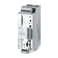
Lenze ECSCA Series Operating Instructions Manual (483 pages)
Axis module ? Application
Brand:
Lenze
| Category:
Control Unit
| Size: 3 MB
Table of Contents
Table of Contents
5
1 Preface and General Information
14
About These Operating Instructions
14
Conventions Used in this Manual
14
Terminology Used
15
Code Descriptions
16
Structure of the System Block Descriptions
17
Features of the Ecsxa Axis Module
18
Scope of Supply
19
Legal Regulations
20
System Block Introduction
21
System Blocks ˘ Principle
21
Node Numbers
22
Access Via System Variables
23
Access Via Absolute Addresses
24
Definition of the Inputs/Outputs
24
Integrate System Blocks into DDS
26
Signal Types and Scaling
27
2 Safety Instructions
28
General Safety and Application Notes for Lenze Controllers
28
Thermal Motor Monitoring
32
Forced Ventilated or Naturally Ventilated Motors
33
Self−Ventilated Motors
34
Residual Hazards
36
Safety Instructions for the Installation According to UL
38
Notes Used
39
3 Technical Data
40
General Data and Operating Conditions
40
Rated Data
42
Current Characteristics
44
Increased Continuous Current Depending on the Control Factor
44
Device Protection by Current Derating
47
4 Mechanical Installation
48
Important Notes
48
Mounting with Fixing Rails (Standard Installation)
49
Dimensions
49
Mounting Steps
50
Mounting with Thermal Separation (Push−Through Technique)
51
Dimensions
52
Mounting Steps
54
Mounting in Cold−Plate Design
55
Dimensions
56
Mounting Steps
57
5 Electrical Installation
58
Installation According to EMC (Installation of a Ce−Typical Drive System)
58
Power Terminals
61
Connection to the DC Bus (+UG, −UG)
64
Connection Plan for Mimimum Wiring with Internal Brake Resistor
66
Connection Plan for Mimimum Wiring with External Brake Resistor
68
Motor Connection
70
Motor Holding Brake Connection
71
Connection of an Ecsxk
73
Control Terminals
74
Digital Inputs and Outputs
78
Analog Input
79
Safe Torque off
80
Automation Interface (AIF)
89
Wiring of System Bus (CAN)
90
Wiring of the Feedback System
95
Resolver Connection
96
Encoder Connection
97
Digital Frequency Input/Output (Encoder Simulation)
100
6 Commissioning
102
Before You Start
102
Commissioning Steps (Overview)
103
Carrying out Basic Settings with GDC
104
Loading the Lenze Setting
106
Setting of Mains Data
107
Selecting the Function of the Charging Current Limitation
107
Setting the Voltage Thresholds
108
Entry of Motor Data for Lenze Motors
109
Holding Brake Configuration
111
Setting of the Feedback System for Position and Speed Control
112
Resolver as Position and Speed Encoder
113
Ttl/Sincos Encoder as Position and Speed Encoder
115
Ttl/Sincos Encoder as Position Encoder and Resolver as Speed Encoder
118
Absolute Value Encoder as Position and Speed Encoder
122
Absolute Value Encoder as Position Encoder and Resolver as Speed Encoder
125
Setting the Polarity of Digital Inputs and Outputs
129
Entry of Machine Parameters
130
Controller Enable (CINH = 0)
131
Operation with Motors from Other Manufacturers
132
Entering Motor Data Manually
132
Checking the Direction of Rotation of the Motor Feedback System
135
Adjusting Current Controller
136
Effecting Rotor Position Adjustment
138
Optimising the Drive Behaviour after Start
141
Speed Controller Adjustment
141
Adjustment of Field Controller and Field Weakening Controller
144
Resolver Adjustment
147
7 Parameter Setting
148
General Information
148
Parameter Setting with "Global Drive Control" (GDC)
149
Parameter Setting with the XT EMZ9371BC Keypad
150
Connecting the Keypad
150
Description of the Display Elements
151
Description of the Function Keys
153
Changing and Saving Parameters
154
8 System Bus (CAN / CAN−AUX) Configuration
155
Setting the CAN Node Address and Baud Rate
155
Settings Via DIP Switch
156
Settings Via Codes
158
Individual Addressing
160
Determining the Boot−Up Master for the Drive System
162
Setting the Boot−Up Time/Cycle Time
163
Reset Node
165
Axis Synchronisation (CAN Synchronisation)
166
Monitoring of the Synchronisation (Sync Time Slot)
169
Axis Synchronisation Via CAN
170
Axis Synchronisation Via Terminal X6/DI1
171
Node Guarding
172
CAN Management
174
Mapping Indices to Codes
175
Diagnostics Codes
177
CAN Bus Status (C0359/C2459)
177
CAN Telegram Counter (C0360/2460)
178
CAN Bus Load (C0361/2461)
179
Remote Parameterisation (Gateway Function)
180
9 Configuring the AIF Interface (X1)
182
CAN Baud Rate
182
CAN Boot up (AIF)
183
Node Address (Node ID)
184
Identifiers of the Process Data Objects
185
Individual Identifier Assignment
186
Display of the Identifier Set
187
Cycle Time (XCAN1_OUT
188
Synchronisation
190
XCAN Sync Response
190
XCAN Sync Identifier
190
XCAN Sync Tx Transmission Cycle
191
Reset Node
191
Monitoring
192
Time Monitoring for XCAN1_IN
192
Bus off
193
Operating Status of AIF Interface
195
10 Monitoring Functions
196
Fault Responses
197
Overview of Monitoring Functions
198
Configuring Monitoring Functions
202
Monitoring Times for Process Data Input Objects
202
Time−Out Monitoring for Activated Remote Parameterisation
204
Short Circuit Monitoring (OC1)
205
Earth Fault Monitoring (OC2)
205
Motor Temperature Monitoring (OH3, OH7)
206
Heatsink Temperature Monitoring (OH, OH4)
208
Monitoring of Internal Device Temperature (OH1, OH5)
209
Function Monitoring of Thermal Sensors (H10, H11)
210
Current Load of Controller (I X T Monitoring: OC5, OC7)
211
Current Load of Motor (I2 X T Monitoring: OC6, OC8)
214
DC−Bus Voltage Monitoring (OU, LU)
218
Voltage Supply Monitoring − Control Electronics (U15)
221
Motor Phase Failure Monitoring (LP1)
221
Monitoring of the Resolver Cable (Sd2)
222
Motor Temperature Sensor Monitoring (Sd6)
223
Monitoring of the Absolute Value Encoder Initialisation (Sd7)
224
Sin/Cos Signal Monitoring (Sd8)
225
Monitoring of the Speed System Deviation (Nerr)
226
Monitoring of Max. System Speed (NMAX)
227
Monitoring of the Rotor Position Adjustment (PL)
228
11 Diagnostics
229
Diagnostics with Global Drive Control (GDC)
229
Diagnostics with Global Drive Oscilloscope (GDO)
230
GDO Buttons
231
Diagnostics with the XT EMZ9371BC Keypad
232
Diagnostics with Pcan−View
233
Monitoring of Telegram Traffic on the CAN Bus
233
Setting All CAN Nodes to the "Operational" Status
235
12 Troubleshooting and Fault Elimination
236
Fault Analysis
236
Fault Analysis Via LECOM Status Words (C0150/C0155)
239
Malfunction of the Drive
241
Fault Messages
242
Causes and Remedies
246
Reset Fault Messages (TRIP−RESET)
254
13 System Blocks
255
Aif_Io_Management (Node Number 161)
255
Outputs_Aif_Management
258
Aif1_Io_Automationinterface (Node Number 41)
259
Inputs_Aif1
259
Outputs_Aif1
264
Aif2_Io_Automationinterface (Node Number 42)
267
Inputs_Aif2
267
Outputs_Aif2
270
Aif3_Io_Automationinterface (Node Number 43)
271
Inputs_Aif3
271
Outputs_Aif3
273
ANALOG1_IO (Node Number 11)
275
Can_Management (Node Number 101)
277
Can_Synchronization (Node Number 102)
281
CAN1_IO (Node Number 31)
283
CAN2_IO (Node Number 32)
289
CAN3_IO (Node Number 33)
294
Inputs_Can3
297
Outputs_Can3
298
Canaux_Management (Node Number 111)
299
Inputs_Canaux_Management
300
Outputs_Canaux_Management
300
Executing a Reset Node
301
Define Instant of Transmission for Canaux2_Out/Canaux3_Out
301
Status Messages
302
Canaux1_Io (Node Number 34)
303
Inputs_Canaux1
306
Outputs_Canaux1
307
Canaux2_Io (Node Number 35)
309
Inputs_Canaux2
312
Outputs_Canaux2
313
Canaux3_Io (Node Number 36)
314
Inputs_Canaux3
317
Outputs_Canaux3
318
Dctrl_Drivecontrol (Node Number 121)
319
Inputs_Dctrl
321
Outputs_Dctrl
323
Quick Stop (QSP)
324
Operation Inhibit (DISABLE)
325
Controller Inhibit (CINH)
325
Setting TRIP (TRIP−SET)
326
Resetting TRIP (TRIP−RESET)
326
Display of Digital Status Signals
327
Device Status
328
TRIP Status (Dctrl_Bexternalfault_B)
329
Transfer of the Status/Control Word Via AIF
329
Dfin_Io_Digitalfrequency (Node Number 21)
331
Inputs_Dfin
331
Dfout_Io_Digitalfrequency (Node Number 22)
338
Inputs_Dfout / Outputs_Dfout
338
DIGITAL_IO (Node Number 1)
343
Inputs_Digital (Digital Inputs)
343
Outputs_Digital (Digital Outputs)
345
Fcode_Freecode (Node Number 141)
347
Mctrl_Motorcontrol (Node Number 131)
351
Inputs_Mctrl
352
Outputs_Mctrl
354
Torque Setpoint / Additional Torque Setpoint
355
Torque Limitation
356
Setting Maximum Speed
357
Speed Setpoint Limitation
358
Torque Control with Speed Limitation
359
Parameterising Phase Controllers
360
Quick Stop (QSP)
361
Manual Field Weakening
362
Switching Frequency Changeover
363
Touch Probe (TP)
364
Adjusting the Motor Data
366
Monitoring
369
Osc_Oscilloscope (Node Number 60)
371
SYSTEM_FLAGS (System Flags, Node Number 151)
372
Inputs SYSTEM_FLAGS
372
Outputs SYSTEM_FLAGS
373
14 Appendix
374
PLC Functionality
374
Extendability / Networking
375
Memories
376
Retain Memory
376
Persistent Memory
377
Download of Various Data Items
379
Temporary Codes
380
RAM Memory Access Via Codes
381
System Program Organisation Units
383
Code Table
384
Table of Attributes
431
General Information about the System Bus (CAN)
440
Overview of Accessories
460
Connector Sets
460
Components for Operation and Communication
461
Brake Resistor
462
Mains Chokes
465
RFI Filters
466
15 Index
467
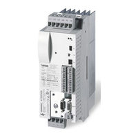
Lenze ECSCA Series Mounting Instructions (214 pages)
Axis module in cold plate design
Brand:
Lenze
| Category:
Servo Drives
| Size: 1 MB
Table of Contents
Deutsch
7
Table of Contents
7
1 Über diese Dokumentation
8
2 Sicherheitshinweise
9
Allgemeine Sicherheits− und Anwendungshinweise für Lenze−Antriebsregler
9
Motor Thermisch Überwachen
13
Fremdbelüftete oder Selbstgekühlte Motoren
15
Eigenbelüftete Motoren
17
Restgefahren
20
Sicherheitshinweise für die Installation nach UL/CSA
22
3 Technische Daten
24
Allgemeine Daten und Einsatzbedingungen
24
Bemessungsdaten
27
4 Mechanische Installation
29
Wichtige Hinweise
29
Montage in Cold−Plate−Technik
30
Abmessungen
31
Montageschritte
32
5 Elektrische Installation
33
Emv−Gerechte Installation (Aufbau des Ce−Typischen Antriebssystems)
33
Leistungsanschlüsse
36
Anschluss an den DC−Zwischenkreis (+UG, −UG)
40
Anschluss Motor
43
Anschluss Motorhaltebremse
44
Steueranschlüsse
46
Digitale Eingänge und Ausgänge
50
Analog−Eingang
51
Sicher Abgeschaltetes Moment
53
Systembus (CAN) Verdrahten
59
Rückführsystem Verdrahten
63
Anschluss Resolver
64
Anschluss Encoder
65
Leitfrequenzeingang/−Ausgang (Encoder−Nachbildung)
69
6 Installation Überprüfen
72
English
77
1 About this Documentation
78
2 Safety Instructions
79
General Safety and Application Notes for Lenze Controllers
79
Thermal Motor Monitoring
83
Forced Ventilated or Naturally Ventilated Motors
85
Self−Ventilated Motors
87
Residual Hazards
90
Safety Instructions for the Installation According to UL
92
3 Technical Data
94
General Data and Operating Conditions
94
Rated Data
97
4 Mechanical Installation
99
Important Notes
99
Mounting in Cold−Plate Design
100
Dimensions
101
Mounting Steps
102
5 Electrical Installation
103
Installation According to EMC (Installation of a Ce−Typical Drive System)
103
Power Terminals
106
Connection to the DC Bus (+UG, −UG)
110
Motor Connection
114
Motor Holding Brake Connection
115
Control Terminals
117
Digital Inputs and Outputs
121
Analog Input
122
Safe Torque off
124
Wiring of System Bus (CAN)
130
Wiring of the Feedback System
134
Resolver Connection
135
Encoder Connection
136
Digital Frequency Input/Output (Encoder Simulation)
140
6 Installation Check
143
Français
147
1 Présentation du Document
148
2 Consignes de Sécurité
149
Consignes Générales de Sécurité Et D'utilisation Relatives Aux Variateurs Lenze
149
Surveillance de la Température du Moteur
153
Moteurs Avec Motoventilation Ou Refroidissement Naturel
155
Moteurs Avec Autoventilation
157
Dangers Résiduels
160
Consignes de Sécurité Pour L'installation Selon UL
162
3 Spécifications Techniques
164
Caractéristiques Générales Et Conditions D'utilisation
164
Caractéristiques Assignées
167
4 Installation Mécanique
169
Remarques Importantes
169
Montage Sur Semelle de Refroidissement
170
Cotes
171
Opérations de Montage
172
5 Installation Électrique
174
Câblage Conforme CEM (Installation D'un Système D'entraînement CE)
174
Partie Puissance
177
Raccordement du Bus CC (+UG, −UG)
181
Raccordement du Moteur
184
Raccordement du Frein de Parking
185
Partie Commande
187
Entrées Et Sorties Numériques
191
Entrée Analogique
192
Absence Sûre de Couple
194
Câblage du Bus Système (CAN)
200
Câblage du Système de Bouclage
204
Raccordement du Résolveur
205
Raccordement du Codeur
206
Entrée/Sortie Fréquence Maître (Émulation Codeur)
210
6 Vérification de L'installation
213
Advertisement
Advertisement
Related Products
Lenze ECSCP Series
Lenze ECSCM Series
Lenze ECSCS Series
Lenze ECSEK002
Lenze ECS A Series
Lenze ECS S Series
Lenze ECS M Series
Lenze ECS 064 Series
Lenze ECS A032 Series
Lenze ECSE 008 Series
Lenze Categories
DC Drives
Control Unit
Inverter
Engine
Controller
More Lenze Manuals
Login
Sign In
OR
Sign in with Facebook
Sign in with Google
Upload manual
Upload from disk
Upload from URL