Sign In
Upload
Manuals
Brands
Kuka Manuals
Controller
KR C2
Kuka KR C2 Manuals
Manuals and User Guides for Kuka KR C2. We have
5
Kuka KR C2 manuals available for free PDF download: Operating Instructions Manual, Assembly Instructions Manual, Operating Handbook, User Manual
Kuka KR C2 Operating Instructions Manual (215 pages)
edition 2005
Brand:
Kuka
| Category:
Control Systems
| Size: 12 MB
Table of Contents
Table of Contents
3
Introduction
9
Industrial Robot Documentation
9
Representation of Warnings and Notes
9
Terms Used
9
Purpose
11
Target Group
11
Intended Use
11
Product Description
13
Overview of the Industrial Robot
13
Overview of the Robot Controller
13
Description of the Control PC
14
Control PC Interfaces
15
PCI Slot Assignment
16
Motherboard
16
Hard Drive
18
Multi-Function Card (MFC3)
18
Digital Servo-Electronics (DSE-IBS-C33)
19
Overview of Resolver Digital Converter (RDC)
20
Resolver Digital Converter
20
Force Sensor Card (KSK) for RDC (Option)
22
KSK Switch Box (Option)
23
Fast Measurement with RDC (Option)
24
Saferdc
26
I/O Print Card for Saferdc
28
Force Sensor Card for Saferdc (Option)
29
Fast Measurement with Saferdc (Option)
29
KUKA VGA Card (KVGA)
30
Batteries
31
Description of the KUKA Control Panel (KCP)
31
Front View
32
Rear View
33
KCP Coupler (Optional)
33
Electronic Safety Circuit (ESC) Safety Logic
35
ESC Nodes
36
Overview of CI3 Boards
37
CI3 Standard Board
38
CI3 Extended Board
40
CI3 Bus Board
41
CI3 Tech Board
43
Description of the Power Unit
44
Fuses
45
Power Supply Unit KPS 600
46
Low-Voltage Power Supply KPS-27
48
KUKA Servo Drive (KSD)
49
Mains Filter
50
Cabinet Cooling
50
Description of Interfaces
51
Power Supply Connection X1/XS1
53
KCP Connector X19
54
Motor Connector X20, Axes 1 to 6
55
Motor Connector X7 (Optional)
56
Data Cable X21, Axes 1 to 8
57
Saferobot X21.1
57
Interface X40
59
Safe KSK XA7
60
Safe KSK XA8
61
Description of the Mounting Plate for Customer Components (Optional)
61
Technical Data
63
Robot Controller
63
Saferdc
65
KCP Coupler (Optional)
66
Dimensions of Robot Controller
66
Minimum Clearances, Robot Controller
67
Minimum Clearances, Top-Mounted / Technology Cabinet
68
Dimensions of Boreholes for Floor Mounting
68
Swing Range for Cabinet Door
69
Plates and Labels
69
Safety
73
General
73
Liability
73
Intended Use of the Industrial Robot
73
EC Declaration of Conformity and Declaration of Incorporation
74
Terms Used
75
Personnel
75
Workspace, Safety Zone and Danger Zone
77
Triggers for Stop Reactions
77
Safety Functions
78
Overview of Safety Functions
78
ESC Safety Logic
79
Mode Selector Switch
79
Operator Safety
80
EMERGENCY STOP Device
81
External EMERGENCY STOP Device
82
Enabling Device
82
External Enabling Device
83
Additional Protective Equipment
83
Jog Mode
83
Software Limit Switches
83
Mechanical End Stops
84
Mechanical Axis Range Limitation (Optional)
84
Axis Range Monitoring (Optional)
84
Release Device (Optional)
85
KCP Coupler (Optional)
85
Labeling on the Industrial Robot
85
External Safeguards
86
Overview of Operating Modes and Safety Functions
86
Emergency Stop
86
Safety Measures
87
General Safety Measures
87
Testing Safety-Related Controller Components
88
Transportation
88
Start-Up and Recommissioning
89
Virus Protection and Network Security
91
Manual Mode
91
Simulation
92
Automatic Mode
92
Maintenance and Repair
92
Decommissioning, Storage and Disposal
94
Safety Measures for "Single Point of Control
94
Applied Norms and Regulations
95
Planning
97
Overview of Planning
97
Electromagnetic Compatibility (EMC)
97
Installation Conditions
98
Connection Conditions
100
Power Supply Connection
101
Power Supply Connection Via X1 Harting Connector
102
Power Supply Connection Via CEE Connector XS1
102
EMERGENCY STOP Circuit and Safeguard
102
Interface X11
105
PE Equipotential Bonding
109
Load Voltage US1 and US2 (Optional)
111
Visualization of the KCP Coupler (Option)
111
RDC Power Supply for Fast Measurement (Option)
111
Saferdc Power Supply for Fast Measurement (Option)
112
Performance Level
114
PFH Values of the Safety Functions
114
Transportation
117
Transportation with the Set of Rollers (Optional)
117
Transportation Using Lifting Tackle
117
Transportation by Pallet Truck
118
Transportation by Fork Lift Truck
119
Start-Up and Recommissioning
121
Start-Up Overview
121
Installing the Robot Controller
123
Connecting the Connecting Cables
123
Connecting the KCP
124
Connecting the PE Equipotential Bonding
124
Connecting the Robot Controller to the Power Supply
124
Reversing the Battery Discharge Protection Measures
124
Connecting the EMERGENCY STOP Circuit and Safeguard
125
Configuring and Connecting Connector X11
125
Switching on the Robot Controller
125
Checking the Direction of Rotation of the External Fan
125
Operation
127
Display and Operator Control Elements of the KCP Coupler (Optional)
127
Uncoupling the KCP
127
Coupling the KCP
128
Booting the Robot Controller from a KUKA USB Stick
128
Maintenance
129
Cleaning the Robot Controller
130
Repair
131
Wiring Example X11
131
Exchanging the Internal Fan
132
Exchanging the External Fan
133
Removal, Installation of the Control PC
134
Exchanging the PC Fans
134
Exchanging the Motherboard Battery
135
Exchanging the Motherboard
135
Exchanging DIMM Memory Modules
135
Exchanging the KVGA Card
136
KVGA Card Settings
137
Exchanging the MFC3 Card
137
Exchanging the DSE-IBS-C33 Card
137
Exchanging the Hard Drive
138
Exchanging the CI3 Board
139
Exchanging the RDC Board
139
Exchanging the Force Sensor Card for RDC
141
Exchanging the Saferdc Board
141
Exchanging the Force Sensor Card for Saferdc
143
Exchanging the I/O Print Board for Saferdc
144
Exchanging the Batteries
145
Exchanging the KPS600
146
Exchanging the KSD
147
Exchanging the KPS-27
148
Exchanging the KCP Coupler Card
148
Exchanging the Pressure Relief Plug
149
Installing the KUKA System Software (KSS)
150
Troubleshooting
151
Repair and Procurement of Spare Parts
151
Control PC Errors
151
MFC3 Errors
152
Field Bus Communication Errors
153
Checking the KCP
153
Fuses and LED Indicators on the CI3 Board
154
CI3 Standard Board
154
CI3 Extended Board
155
CI3 Bus Board
157
CI3 Tech Board
158
Checking the KPS600
160
Checking the KPS-27
163
Testing the KSD
163
Heat Sink Temperature
164
Checking the Temperature Sensor Ballast Resistor
165
Checking the Fans
166
Checking the Motor Winding and Brake
166
Checking the DSE-IBS-C33
167
KCP Coupler LED Display (Optional)
167
KCP Coupler Troubleshooting
169
Leds on the RDC Board
170
Leds on the Saferdc Board
170
Leds on the Force Sensor Card (KSK) for Saferdc (Option)
173
Leds on the I/O Print Board
173
Checking the Saferdc
174
DSE-RDW Diagnosis
174
Description of the User Interface
175
Setting the Language
176
MFC3 Register Display
176
DSE-IBS Information
177
RDC Table
178
RDC Offset and Symmetry Adjustment
178
Check RDC-DSE Communication
179
Drive Bus Diagnostics
181
Drive Bus Error List
181
Drive Bus - KPS
182
Drive Bus - KSD-16
184
KPS600 Error Messages
185
KSD Error Message
186
ESC Diagnosis
186
User Interface
186
Log File
187
ESC Circuit Reset
187
Terminating ESC Diagnosis
187
State Display of the ESC Nodes
188
Troubleshooting
189
Error Display of the ESC Nodes
189
Displaying All Status Bits
191
Configuring Controllers
192
Configuring the Controller Properties
193
Configuring ESC Nodes
194
Selecting the Display for Signals
195
Selecting the Properties of the ESC Node
196
Assigning ESC Nodes to a Controller
197
Error Messages and Troubleshooting
197
KUKA Service
201
Requesting Support
201
KUKA Customer Support
201
Advertisement
Kuka KR C2 Operating Instructions Manual (157 pages)
Brand:
Kuka
| Category:
Robotics
| Size: 6 MB
Table of Contents
Table of Contents
3
Introduction
9
Target Group
9
Robot System Documentation
9
Representation of Warnings and Notes
9
Terms Used
9
Product Description
11
Overview of the Robot System
11
Overview of the Robot Controller
11
Description of the Control PC
12
PC Interfaces
13
PC Slot Assignment
14
Motherboard
15
Hard Drive
16
CD-ROM Drive (Optional)
16
Floppy Disk Drive (Optional)
16
Multi-Function Card (MFC3)
16
Digital Servo-Electronics (DSE-IBS-C33)
18
KUKA VGA Card (KVGA)
18
Batteries
19
Description of the KUKA Control Panel (KCP)
19
Front View
20
Rear View
21
KCP Coupler (Optional)
21
Electronic Safety Circuit (ESC) Safety Logic
23
ESC Nodes
24
Overview of CI3 Boards
25
CI3 Standard Board
26
CI3 Extended Board
28
CI3 Bus Board
29
CI3 Tech Board
31
Description of the Power Unit
32
Power Supply Unit KPS600
33
Fuses
35
Low-Voltage Power Supply KPS-27
36
KUKA Servo Drive (KSD)
36
Mains Filter
38
Cabinet Cooling
38
Description of Interfaces
39
Power Supply Connection
40
KCP Connector X19
42
Motor Connector X20, Axes 1 to 6
43
Motor Connector X7 (Optional)
44
Data Cable X21, Axes 1 to 8
45
Description of the Mounting Plate for Customer Components (Optional)
45
Technical Data
47
Basic Data
47
KCP Coupler (Optional)
48
Dimensions of Robot Controller
49
Minimum Clearances, Robot Controller
49
Minimum Clearances, Top-Mounted / Technology Cabinet
50
Swing Range for Cabinet Door
50
Plates and Labels
50
Safety
53
System Planning
53
EC Declaration of Conformity and Declaration of Incorporation
53
Installation Site
53
External Safeguards
53
Workspace, Safety Zone and Danger Zone
54
Description
55
Category of the Safety-Oriented Circuits
55
Stop Reactions
55
Labeling on the Robot System
56
Safety Information
56
Safety Features
57
Overview of the Safety Features
57
ESC Safety Logic
57
Operator Safety Input
57
EMERGENCY STOP Button
58
Enabling Switches
58
Jog Mode
59
Mechanical End Stops
59
Mechanical Axis Range Limitation (Option)
59
Axis Range Monitoring (Option)
60
Software Limit Switches
60
Release Device (Option)
60
Kuka.saferobot (Option)
61
Personnel
61
Safety Measures
62
General Safety Measures
62
Transportation
63
Start-Up
63
Programming
64
Automatic Mode
64
Planning
65
Overview of Planning
65
Electromagnetic Compatibility (EMC)
65
Installation Conditions
66
Connection Conditions
67
Power Supply Connection
68
Power Supply Connection Via X1 Harting Connector
69
Power Supply Connection Via CEE Connector XS1
69
EMERGENCY STOP Circuit and Safeguard
70
Interface X11
71
PE Equipotential Bonding
74
Planning the KCP Coupler Option
75
Transportation
77
Transportation Using Lifting Tackle
77
Transportation by Pallet Truck
78
Transportation by Fork Lift Truck
78
Start-Up
79
Start-Up Overview
79
Installing the Robot Controller
80
Connecting the Connecting Cables
80
Connecting the KCP
81
Connecting the PE Equipotential Bonding
81
Connecting the Robot Controller to the Power Supply
81
Reversing the Battery Discharge Protection Measures
82
Connecting the EMERGENCY STOP Circuit and Safeguard
82
Configuring and Connecting Connector X11
82
Switching on the Robot Controller
82
Checking the Direction of Rotation of the External Fan
83
Operation
85
Display and Operator Control Elements of the KCP Coupler (Optional)
85
Uncoupling the KCP
85
Coupling the KCP
85
Booting the Robot Controller from a USB Stick
86
Maintenance
87
Maintenance Table
87
Cleaning the Robot Controller
88
Repair
89
Service Jumper Plug X11
89
Exchanging the Internal Fan
90
Exchanging the External Fan
91
Exchanging the Pressure Relief Plug
91
Exchanging the PC
92
Exchanging the PC Fans
93
Exchanging the Motherboard Battery
94
Exchanging the Motherboard
94
Exchanging DIMM Memory Modules
94
Exchanging the Batteries
95
Removal and Installation of the CD-ROM Drive (Optional)
96
Removal and Installation of the Floppy Disk Drive (Optional)
97
Exchanging the Hard Drive
98
Exchanging the KVGA Card
98
KVGA Card Settings
99
Exchanging the MFC3 Card
99
Exchanging the DSE-IBS-C33 Card
99
Exchanging the KPS600
100
Exchanging the KPS-27
100
Exchanging the KSD
101
Removal and Installation of the KCP Coupler
102
Installing the KUKA System Software (KSS)
102
Troubleshooting
103
Repair and Procurement of Spare Parts
103
PC Fault Profiles
103
MFC3 Error Messages
105
KCP Error Messages
105
Field Bus Communication Error Messages
106
Fuses and LED Indicators on the CI3 Board
106
CI3 Standard Board
106
CI3 Extended Board
108
CI3 Bus Board
109
CI3 Tech Board
110
KPS 600 Fuses, Messages and Error Displays
112
Error Messages
115
Error Messages on the KSD
115
KCP Coupler LED Display (Optional)
117
KCP Coupler Troubleshooting
119
DSE-RDW Diagnosis
120
Description of the User Interface
120
Setting the Language
121
MFC3 Register Display
121
DSE IBS Information
122
RDC Table
123
RDC Offset and Symmetry Adjustment
124
Check RDC-DSE Communication
125
Drive Bus Diagnostics
127
Drive Bus Error List
128
Drive Bus - KPS
128
Drive Bus - KSD-16
130
KPS600 Error Messages
131
KSD Error Messages
132
ESC Diagnosis
132
User Interface
132
Log File
133
ESC Circuit Reset
133
Terminating ESC Diagnosis
133
State Display of the ESC Nodes
134
Error Display of the ESC Nodes
135
Displaying All Status Bits
136
Configuring Controllers
137
Configuring the Controller Properties
138
Configuring ESC Nodes
139
Selecting the Display for Signals
140
Selecting the Properties of the ESC Node
141
Assigning ESC Nodes to a Controller
142
Error Messages and Troubleshooting
142
Appendix
145
KUKA Service
147
Requesting Support
147
KUKA Customer Support
147
Index
153
Kuka KR C2 Operating Handbook (96 pages)
Machine Data
Brand:
Kuka
| Category:
Controller
| Size: 0 MB
Table of Contents
Table of Contents
3
1 Introduction
8
Characteristics
8
System Requirements
8
Software
8
Hardware
8
2 The File $MACHINE.DAT
9
Description of the Individual Machine Data
9
V_R1Mada[ ]
9
Tech_Max
9
Num_Ax
10
Axis_Type[ ]
11
Coup_Comp[ ]
11
Excoup_Comp[ ]
11
Mames[ ]
12
Robroot
13
Ersysroot
14
Rat_Mot_Ax[ ]
15
Rat_Mot_Enc[ ]
16
Dsechannel[ ]
16
Pmchannel[ ]
18
Loop_Lg_Ptp[ ]
19
Loop_G_Vel_Ptp[ ]
19
Loop_I_Vel_Ptp[ ]
20
Loop_Direction[ ]
20
Slave_Loop_Fol_Critical[ ]
20
Slave_Loop_Fol_Alarm[ ]
21
Slave_Loop_Speed_Alarm[ ]
21
Slave_Loop_Pmchannel[Ln]
21
Loop_Type[Ln]
21
Loop_Type_Attribute[ ]
22
Master_Loop[Ln]
22
Slave_Torque_Ratio[ ]
23
Ninput_Sensortype[Ln]
23
Ninput_Sensorchannel[Ln]
24
Ninput_Subchannel[Ln]
24
Posinput_Sensortype[Ln]
25
Posinput_Sensorchannel[Ln]
25
Posinput_Subchannel[Ln]
25
Torqinput_Sensortype[Ln]
26
Loop_Rat_Mot_Ax[ ]
26
Loop_Rat_Extpos_Ax[ ]
26
Motor_Pole_Number[ ]
27
Servofile_Config[ ]
27
Servofilekps1[ ]
27
Curr_Max[ ]
28
Curr_Cal[ ]
28
Curr_Lim[I]
29
Curr_Mon[I]
29
Kps_Curr_Max
30
Kps_Curr_Rated
30
Curr_Com_Ex[ ]
30
Kt_Mot[ ]
31
Kt0_Mot[ ]
31
Raise_Time[ ]
31
Raise_T_Mot[ ]
32
Vel_Axis_Ma[ ]
32
Vel_Cpt1_Ma
33
Vel_Dse_Ma[ ]
33
Axis_Reso[ ]
33
Red_Vel_Axc[ ]
34
Red_Acc_Axc[ ]
34
Red_Acc_Dyn
35
Red_Vel_Cpc
35
Red_Acc_Cpc
35
Vel_Cp_T1
35
Vel_Cp_Com
35
Red_Jus_Ueb
36
Red_Acc_Ov[ ]
36
Acc_Car_Tool
36
Acc_Car_Limit
37
Acc_Car_Act
37
Acc_Car_Stop
37
Red_Acc_Emx[ ]
38
Warmup_Red_Vel
38
Warmup_Time
39
Cooldown_Time
39
Warmup_Curr_Limit
39
Warmup_Min_Fac
39
Warmup_Slew_Rate
39
St_Tol_Vel[ ]
40
St_Tol_Time
40
Bounce_Time
41
Vel_Ax_Jus[ ]
41
Sen_Del[ ]
41
L_Emt_Max[ ]
42
G_Vel_Cal
42
Lg_Ptp[ ]
42
Lg_Cp[ ]
43
Tc_Sym
43
Decel_Mb[]
43
G_Coe_Cur
44
G_Vel_Ptp[ ]
44
G_Vel_Cp[ ]
44
I_Vel_Ptp[ ]
45
I_Vel_Cp[ ]
45
Vel_Filt[ ]
46
Tm_Con_Vel
46
Apo_Dis_Ptp[ ]
46
Acc_Ma
47
Vel_Ma
47
Acc_Ov
48
Red_T1
48
Def_Flt_Ptp
48
Def_Flt_Cp
48
Def_Ov_Jog
49
Ana_Del_Flt
49
100 $Seq_Cal
49
101 $Dir_Cal
49
102 $Red_Cal_Sd
50
103 $Red_Cal_Sf
50
104 $Brk_Mode
50
Maschinendaten 12.0400 en
51
105 $Brk_Opentm
52
106 $Brk_Del_Com
52
107 $Brk_Del_Pro
53
108 $Brk_Del_Ex
54
109 $Serv_Off_Tm
54
110 $Ms_Da
54
111 $Ffc_Vel
55
112 $Ffc_Torq
55
113 $Geartorq_Mon
55
114 $Servomode
56
115 $Acc_Act_Ma
56
116 $Vel_Act_Ma
56
117 $In_Pos_Car
57
118 $In_Pos_Ori
57
119 $In_Pos_Ma[ ]
58
120 $Time_Pos[ ]
59
121 $In_Still_Ma
59
122 $Fol_Err_Ma[ ]
60
123 $Vel_Enc_Co
60
124 $Com_Val_Mi[ ]
60
125 $Tl_Com_Val
61
126 $Touch_Vel
61
127 $Touch_Acc
61
128 $Softn_End[ ]
61
129 $Softp_End[ ]
62
130 $Axworkspace
62
131 $Brk_Max_Tm
62
132 $Emstop_Time
63
133 $Act_Val_Dif
63
134 $Trafoname
63
135 $Kinclass
63
136 $Ax_Sim_On
64
137 $Simulated_Axis
64
138 $Trafo_Axis
65
139 $Main_Axis
65
Maschinendaten 12.0400 en
66
Maschinendaten 12.0400 en
67
Maschinendaten 12.0400 en
68
140 $Wrist_Axis
69
141 $A4_Par
69
142 $Def_A4Fix
70
143 $Def_A5Link
70
144 $Spindle
71
145 $Axis_Seq
71
146 $Axis_Dir[ ]
72
147 $Inc_Axis
72
148 $Inc_Extax[ ]
73
149 $Inc_Car[ ]
73
150 $Pos_Swb[ ]
73
151 $Singul_Pos
74
152 $Dis_Wrp1
74
153 $Dis_Wrp2
74
154 $Ori_Check
75
155 $Tiroro
75
156 $Tflwp
76
157 $Tx3P3
76
158 $Length_A
76
159 $Length_B
76
160 $Dh_4
77
161 $Dh_5
77
162 $Spin_A
78
163 $Spin_B
78
164 $Spin_C
78
165 $Trp_A
78
166 $Spc_Kin
79
167 $Asr_Error
79
168 $Rat_Ext_Enc
79
169 $Ax_Energy_Max[ ]
80
169.1Kinetic Energy
80
169.2Potential Energy
81
169.3Maximum Energy of the Linear Unit
81
169.4Maximum Energy of a Turntable
81
170 $Brk_Energy_Max[ ]
81
171 $Brk_Cool_Off_Coeff[ ]
81
172 $Brk_Torque[ ]
82
Machine Data for External Axes
83
Ex_Ax_Num
83
Ex_Ax_Async
84
Async_T1_Fast
84
Maschinendaten 12.0400 en
85
Async_Ex_Ax_Decouple
86
Interaction with System Variables
87
Ex_Kin
88
Et1_Ax
88
Et1_Name[ ]
89
Et1_Ta1Kr
89
Et1_Ta2A1
90
Et1_Ta3A2
90
Et1_Tfla3
90
Et1_Tpinfl
91
Advertisement
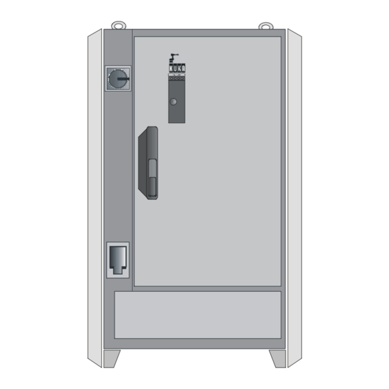
Kuka KR C2 User Manual (89 pages)
CONTROL CABINET
Brand:
Kuka
| Category:
Controller
| Size: 1 MB
Table of Contents
Table of Contents
3
1 Repair and Procurement of Spare Parts
7
Customer Repair
7
Repair by KUKA Service Personnel
7
Procurement of Spare Parts
7
2 Fault Analysis and Elimination
8
Fault Analysis
8
Isolation of Faults Using Checklists
8
Isolation of Faults by Exchanging Components
8
3 Typical Fault Profiles
9
Fault Profiles Related to the PC
9
Power Supply
9
Basic Configuration
9
Drives
9
PC--Related Peripherals
9
Fault Profile Checklist
10
Fault Profiles Related to DSE and Machine Data
15
Program Crashes (with Possible Loss of Mastering)
15
The Robot Does Not Move in Jog Mode
15
The Drives Cannot be Switched on
16
DSE Error Messages When Booting the System
17
DSE X Not Found
17
Memory Test Error DSE X
17
DSE X Does Not Run up
17
DSE Axis Assignment Ax
18
Power Module Axis Ax Not / Incorrectly Connected
18
Machine Data Loader Canceled
18
Incorrect Machine Data
18
DSE Error Messages During Operation
19
Watchdog Interpolation Cycle Ax
19
Synchronization Error with DSE Ax
19
Regulator Limit Exceeded Ax
19
Stopped Ax
19
Motor Temperature Ax
19
Fault Profiles Related to the MFC
20
Controller Hangs When Loading Software Components
20
KCP Control Panel Does Not Work
20
No Image on KCP
20
Operating Mode Switchover on KCP Does Not React
21
When PC Is Booted, the Operating System Vxworks Does Not Run up
21
Fault Profiles Related to the KCP
22
No Display on the LCD
22
Drives Cannot be Switched on
22
No Entries Can be Made Via KCP
22
EMERGENCY STOP Cannot be Acknowledged
23
Space Mouse Does Not Work
23
Fault Profiles Related to a Field Bus Card
24
Communication Via Diagnostic Interface Not Possible
24
Error Message "XXXXX I/O Driver Configuration Error
24
After Inserting the Field Bus Card: no Display, Controller Does Not Boot (Stop 0)
24
The Controller "Hangs" after Initialization of the Field Bus Card
24
No External Power Supply for Slave When Controller Switched off
24
4 Servo Drive Module Messages and Error Displays
25
Servo Drive Module Leds (KSD1)
25
KCP Messages for Drives Diagnosis
26
5 KPS- - 600 Messages and Error Displays
27
KPS--600/10 and /20 LED Indicators
27
Meaning of Leds 1 and 2
28
Meaning of Leds 3 and 4
28
Meaning of Leds 5 and 6
28
KPS--600 Error Messages on the KCP
29
6 KPS- -27 Operating State Indicators
31
7 DSE- -IBS Operating State Indicators
32
8 RDC2 Operating State Indicators
33
9 ESC Diagnostic Tool
34
Softkey Bar
35
ESC Diagnosis Error Messages
37
10 DSE- - RDW Diagnostic Tool
39
Main Menu of the DSE--RDW Diagnostic Tool
39
Language Selection
40
System Info
41
MFC2 Register Display
42
DSE IBS Information
43
Display RDC Table
44
RDC Offset and Symmetry Adjustment
45
Check RDC--DSE Communication
46
Drive Bus Diagnostics
47
Drive Bus Error List
48
Drive Bus Diagnostics -- KPS--2
49
Drive Bus KSD 1--16
50
Error Messages Valid for the KPS--600
51
Error Messages Valid for the Ksds
52
11 Oscilloscope
53
Display
53
File Selection
54
Oscilloscope Screen
54
The Information Window
55
The Softkey Bar
56
The Color Softkeys
56
The Scaling Function
57
The Zoom Function
58
The Save Function
58
The R.M.s. Value Function
58
Print
60
The Cursor Functions
60
The Filter Function
63
Superposing Traces
64
Changing Color Assignments
66
Switching Curves on and off
67
Configure
68
General
70
Trigger Condition
71
Trace Status
73
Trace Data
73
Examples of a Trace
77
12 Robot Repair Card
81
Kuka KR C2 Assembly Instructions Manual (106 pages)
Brand:
Kuka
| Category:
Robotics
| Size: 2 MB
Table of Contents
Table of Contents
3
Introduction
7
Documentation of the Industrial Robot
7
Representation of Warnings and Notes
7
Purpose
9
Intended Use
9
Target Group
10
Product Description
11
General
11
Wrist
12
Arm
13
Link Arm
14
Main Axis Motor Units A1 to A3
15
Rotating Column
16
Base Frame
18
Working Range Limitation for A1
19
Working Range Monitoring for A1 and A2
19
Energy Supply System
19
Technical Data
21
General
21
Principal Data
23
Safety
35
Representation of Warnings and Notes
35
General
35
Liability
36
Intended Use of the Industrial Robot
36
EC Declaration of Conformity and Declaration of Incorporation
37
Terms Used
38
Personnel
39
Workspace, Safety Zone and Danger Zone
40
Overview of Protective Equipment
41
Mechanical End Stops
41
Mechanical Axis Range Limitation (Optional)
42
Axis Range Monitoring (Optional)
42
Options for Moving the Manipulator Without Drive Energy
42
Labeling on the Industrial Robot
44
Safety Measures
44
General Safety Regulations
44
Transportation
46
Start--Up and Recommissioning
46
Manual Mode
47
Automatic Mode
48
Maintenance and Repair
48
Decommissioning, Storage and Disposal
50
Applied Norms and Regulations
51
Transportation
53
Installation
57
General
57
Information for Planning
58
Principal Loads
59
Mounting Variants
60
Mounting Base with Centering
60
Machine Frame Mounting
65
Adapter Plate
67
Installation
69
Moving the Manipulator Without Drive Energy
72
Electrical Installations
73
Description
73
Cabling Plans and Wiring Diagrams
77
Wiring Diagram
81
Connecting Cables
83
General
83
Routing of Cables
84
Junction Boxes on the Manipulator
84
Coding
85
Connector Panel on the Control Cabinet
85
Configuration of the Connecting Cables
86
Connector Pin Allocation
87
Tightening Torques
89
Tightening Torques, Standard
89
Consumables, Safety Data Sheets
91
Safety Data Sheet for Optitemp RB1 Cable Grease
91
Toxicological Information
92
Safety Data Sheet for Optimol Olit CLS Lubricating Grease
94
Disposal Information
101
Advertisement
Related Products
Kuka KR C4 compact
Kuka KR C1
Kuka KR 470-2 PA
Kuka KR 30 HA
Kuka KR 60 HA
Kuka KR 350
Kuka KR 20-3
Kuka KR 20-3 C
Kuka KR 30-2
Kuka KR 60-2
Kuka Categories
Robotics
Controller
Industrial Equipment
Indoor Furnishing
Control Systems
More Kuka Manuals
Login
Sign In
OR
Sign in with Facebook
Sign in with Google
Upload manual
Upload from disk
Upload from URL