Sign In
Upload
Manuals
Brands
Kramer Manuals
Remote Control
K-CONFIG
User Manuals: Kramer K-CONFIG Room Controller
Manuals and User Guides for Kramer K-CONFIG Room Controller. We have
1
Kramer K-CONFIG Room Controller manual available for free PDF download: User Manual
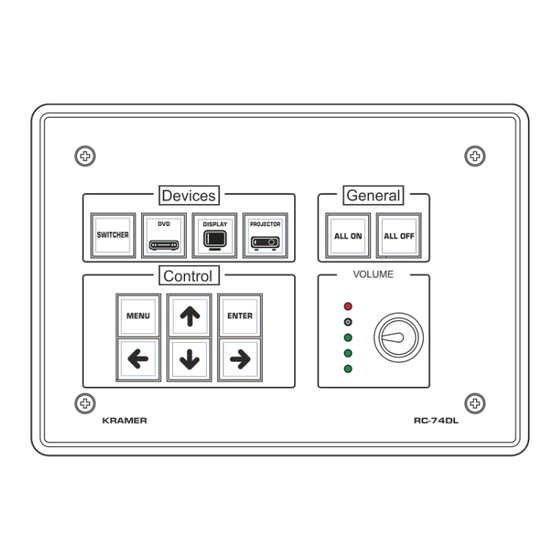
Kramer K-CONFIG User Manual (188 pages)
Room Controller
Brand:
Kramer
| Category:
Remote Control
| Size: 11 MB
Table of Contents
User Manual
1
Table of Contents
2
1 Introduction
8
Overview
8
System Requirements
9
2 Planning the Controlled Room
10
Glossary
14
3 Kramer K-CONFIG Software Installation
16
Installing the ".NET Framework" Revision 4.0 (or Higher) Software
16
Installing the USB Driver
16
Figure 1: USB Driver Installation -USB Installation Attempt
16
Figure 2: USB Driver Installation - Select USB Driver Properties
17
Figure 3: USB Driver Installation -USB Driver Properties Window
17
Figure 4: USB Driver Installation - USB Driver Update
18
Figure 5: USB Driver Installation - USB Driver Location
18
Figure 6: USB Driver Installation - Windows Security
19
Figure 7: USB Driver Installation - USB Driver Updated
19
Installing Kramer K-CONFIG Software
20
Figure 8: USB Driver Installation - USB Recognized on PC
20
Figure 9: Application Installation
20
Figure 10: Installing Kramer K-CONFIG
21
Figure 11: End User License Agreement
21
Figure 12: Registration Window
22
Figure 13: KRAMER K-CONFIG Software
22
Figure 14: Setting a Working Directory
23
Figure 15: Change the Working Directory Window
23
Figure 16: Drive Database Loaded
23
Figure 17: Installation Complete. the Main Window Opens
24
4 Getting to Know K-CONFIG
25
Figure 18: Opening K-CONFIG
25
Figure 19: Opening K-CONFIG
25
Figure 20: Import Drivers Window
26
The Main Window
27
Figure 21: Drivers Tree - with Imported Drivers, Sorted by Vendor, Device Type or by Keyword
27
Figure 22: Opening K-CONFIG Default Layout for the First Time
28
Figure 23: Dragging the Triggers Window
28
Figure 24: Drag and Drop Tool
29
Figure 25: Triggers Window Repositioned
29
Figure 26: Customized Window Setup
30
Figure 27: Adding the Port Manager Window to the K-CONFIG Layout
30
Figure 28: the Port Manager Window Added to the K-CONFIG Layout
31
The K-CONFIG Menus
32
Figure 29: the File Menu
32
Figure 30: New Project Warning
32
Figure 31: Saving a Project
33
Figure 32: Import Devices
34
Figure 33: Import Devices - Message
34
Figure 34: Select Virtual Device to Save
34
Figure 35: Export Device Xml File
35
Figure 36: Export Device Xml
35
Figure 37: the Device Menu
35
Figure 38: the Connection Method Window
36
Figure 39: Connecting to a Master Device - Selecting the Device
36
Figure 40: Connecting to a Master Device - Selecting the Connection Method
36
Figure 41: Connecting to a Master Device - the Connection Details
37
Figure 42: Connecting to a Master Device - Reading the Configuration
37
Figure 43: the Window Menu
37
Figure 44: Window Menu - Web Settings Window
38
Figure 45: Help Menu
38
Figure 46: Help Menu - Check for Updates
39
Figure 47: the Help Menu - about K-CONFIG
39
Figure 48: the Help Menu - Enable Analytics
39
Quick Access Icons
40
Figure 49: the Quick Access Toolbar
40
5 The Driver Manager - Getting Started
41
Getting to Know the Driver Manager
41
Figure 50: the Commands List in the Driver Manager
42
Figure 51: an Empty Command Line
43
Selecting the Driver Manager
44
Figure 52: Selecting the Driver Manager in the File Menu
44
Figure 53: the Drivers Tree
45
Figure 54: Selecting a Sony Driver
45
Figure 55: the Driver Manager Window
46
Figure 56: Driver Details Summary PDF File
47
The Common Commands Tree Editor
48
Figure 57: Open the Common Commands Tree Editor
48
Figure 58: the Common Commands Tree Editor Window - IR, Serial and Replies
48
Figure 59: the Common Commands Tree Editor Window - Tables
49
Figure 60: the Common Commands Tree Editor Window - Queries
49
Figure 61: the Commands Tree Editor Window - Adding a Non-Default Shared Command
50
Figure 62: the Commands Tree Editor Window - Add Command Window
50
Figure 63: the Commands Tree Editor Window - Adding the Command Name
50
Setting the Shared Commands
51
Figure 64: the Driver Manager Window - Non-Default Shared Command Added to the Input List
51
Figure 65: the Driver Manager - Selecting the Device Type
51
Figure 66: the Driver Manager - Dragging the PWR_OFF to the Power Command Group
52
Figure 67: the Driver Manager - Action Copy Message
52
Figure 68: the Driver Manager -PWR_OFF Added to the Power Command Group
52
Serial Commands
53
Figure 69: the Driver Manager - Standard Commands Added
53
Figure 70: Serial Commands
53
Figure 71: Serial Commands -Add New Command Name
54
Figure 72: Serial Commands - the New Command Name
54
Figure 73: Serial Commands -Selecting the New Command Name
54
Figure 74: Serial Commands - New Command Added
55
Figure 75: Testing Serial Commands -Connecting the PC to the Room Controller
56
Figure 76: Testing Serial Commands -Selecting a Device Port
56
Figure 77: Testing Serial Commands -Ethernet Settings for Controlled Device
56
Figure 78: Testing Serial Commands - Setting the Command
57
Figure 79: Testing Serial Commands - Request and Response
57
Figure 80: Testing Serial Commands - Storing the Reply
57
Figure 81: Testing Serial Commands - Serial Reply Stored
58
Figure 82: Testing Serial Commands - Serial Reply Matches Stored Reply
58
Figure 83: IR Commands - Convert Pronto Command Window
59
Figure 84: IR Commands - Pronto Command Converted
59
Figure 85: IR Commands - Connect to the Room Controller Device
60
Figure 86: IR Commands - the Device Is Connected
61
Figure 87: IR Commands - the IR Command String Obtained
61
Figure 88: IR Commands - Selecting a Room Controller Device IR Port
62
Figure 89: IR Emitter Wiring
62
Figure 90: Serial Reply Commands - Selecting a Serial Reply Command
63
Figure 91: Serial Reply Commands - Reading the Serial Reply Command
63
Figure 92: the Driver Manager Window - New Table
64
Figure 93: the Driver Manager Window - Select Number of Rows
65
Figure 94: the Driver Manager Window - Typing Commands
65
Figure 95: the Driver Manager Window - Writing the Commands
66
Figure 96: the Driver Manager Window - Selecting Every 3 Rows
66
Figure 97: the Driver Manager Window - Logarithmic Row Selection
67
Figure 98: the Driver Manager Window - Setting the LED Levels
67
Figure 99: the Driver Manager Window - the Query
68
Figure 100: the Driver Manager Window - the Shared Query
69
Figure 101: the Lamphour Query Details
70
6 Defining the Control Room Via the Project Navigator
71
Adding a Master Room Controller
71
Figure 102: the Project Navigator Window
71
Figure 103: Adding a Master Device to the Project Navigator Window
72
Figure 104: Main Window - Master Device Selected
72
Figure 105: Main Window - Show Unused Ports
73
Figure 106: the Port Manager Window for RC-74DL
73
Figure 107: the Auxiliary Device Window
74
Figure 108: Filtering the Controller Device Name
74
Figure 109: Master Controller Device Shortcuts - Example 1
75
Figure 110: Master Controller Device Shortcuts - Example 2
75
Figure 111: Master Room Controller Device Shortcuts - Example 3
76
Figure 112: Set Automatic Behavior - Message
76
Figure 113: Set Automatic Behavior - Port Manager Example
77
Figure 114: Set Automatic Behavior - RC-13TC with Assigned Ports
77
Figure 115: Set Automatic Behavior - Device Transport Commands Wizard Window
77
Adding Room Controllers
78
Figure 116: the Device View Area for RC-74DL and RC-63DLN
78
Figure 117: the Device View Area for RC-74DL and Four Auxiliary Devices
79
Figure 118: Auxiliary Master Device Shortcuts
79
Figure 119: Auxiliary Device Shortcuts - Set the same as
80
Figure 120: Auxiliary Device Shortcuts - Configure Switch Buttons for RC-3TBU
80
Figure 121: Auxiliary Device Shortcuts - Connect the Device to Your PC
80
Figure 122: Auxiliary Device Shortcuts - Set the Connection Method
81
Figure 123: Auxiliary Device Shortcuts - Selecting Default Drivers
81
Figure 124: Auxiliary Device Shortcuts - Configuring RC-3TBU Buttons
81
Adding a Control Gateway Device
82
Figure 125: Auxiliary Device Shortcuts - Setting Automatic Behavior
82
Figure 126: Adding a Control Gateway Device
82
Figure 127: Control Gateway Device - FC-26 Listed in the Project Navigator
83
Figure 128: Control Gateway Device - Port Manager Window
83
Figure 129: Control Gateway Device - Proxy (Gateway) Port
84
Figure 130: Control Gateway Device - Proxy (Gateway) Ports List
84
Figure 131: Control Gateway Device - Select a Port
84
Figure 132: Control Gateway Device - Select a Port
85
Figure 133: Control Gateway Device - Ethernet Settings for IR Port
85
Figure 134: Control Gateway Device - FC-26 Communication Web Page
85
Figure 135: Control Gateway Device - IR Port Ethernet Settings
86
Figure 136: Control Gateway Device - Port Manager, Assigning an Ethernet Port
86
Figure 137: Control Gateway Device - Assigning All the IR Ports
86
Figure 138: Control Gateway Device - Select Proxy (Gateway) Port
87
Figure 139: Control Gateway Device - FC-26 Serial Port Settings Web Page
87
Figure 140: Control Gateway Device - RS-232 Port Ethernet Settings
87
Figure 141: Control Gateway Device - FC-26 Port Manager
88
Figure 142: Multiple Control Gateways - Selecting the Virtual Ethernet Port
88
Figure 143: Multiple Control Gateway Ports - the Proxy (Gateway) Ports Window
89
Figure 144: Multiple Control Gateway Ports - Selecting Different Proxy (Gateway) Port Types
89
Figure 145: Multiple Control Gateway Ports - Proxy Ports Selected Per Control Gateway
90
Figure 146: Multiple Control Gateway Ports - Selected Proxy (Gateway) Ports in Project Navigator Window
90
Figure 147: Multiple Control Gateway Ports - Selected Proxy (Gateway) Ports in the Port Manager Window
90
The Virtual Device
91
Figure 148: Control Gateway Device Shortcuts
91
Figure 149: Adding a Virtual Device
91
Figure 150: the Basic Virtual Device Front Panel
92
Figure 151: the Virtual Device Properties Window
92
Figure 152: Custom Virtual Device Appearance in K-CONFIG
93
Figure 153: Editing the Virtual Device (Step 1)
93
Figure 154: Editing the Virtual Keypad Device (Step 2)
94
Figure 155: the "DVD Controller" Virtual Device Front Panel
94
Figure 156: Setting the LCD and Button Label Names
94
Figure 157: Setting the Button Behavior
95
Figure 158: Setting the Knob Function
95
Figure 159: Final Appearance of the "Room 1" Virtual Device Front Panel in K-CONFIG
95
Figure 160: Creating a Virtual Panel Template
96
Figure 161: Selecting a Virtual Panel Template
96
Figure 162: Virtual Panel Template in the Device View
96
Figure 163: Setting a Virtual Panel to be the Main Panel
97
Figure 164: New Main Virtual Panel
97
Figure 165: Virtual Device - Link to Another Panel
98
Figure 166: Virtual Device - a Button with a Link
98
Figure 167: Virtual Keypad Device Shortcuts - Saving as a Template
99
Figure 168: Virtual Device Shortcuts - Saved as a Template
99
Figure 169: Virtual Device Shortcuts - New Template Added
99
Figure 170: Virtua Device Shortcuts - Setting the same as
99
Adding the Virtual Device Templates
100
Figure 171: Virtual Device Templates - Selecting the Template
100
Figure 172: Virtual Device Templates - Deselecting Panels
101
Figure 173: Virtual Template Device Shortcuts - Saving as a Template
101
The Room Controller Device View
102
Figure 174: Device View - Editing the Panel Background
102
Figure 175: Device View - Panel Background Examples
102
Figure 176: the Device Front Panel - Adding an Image to a Button
102
Figure 177: the Device Front Panel - Adding a Label to a Button
103
Figure 178: Setting the Button Transparency on a Virtual Panel
103
7 Assigning the Controlled Devices to Master and Auxiliary Device Ports
104
Figure 179: the Control Room Example
104
Figure 180: Select the Port Manager
105
Figure 181: the RC-74DL Port Manager
105
Assigning a Controlled Device Driver to an RS-232 / RS-485 / IR Port
106
Figure 182: the Drivers Tree Window
106
Figure 183: Select the Driver
106
Figure 184: Assigning a Driver to a Port
107
Figure 185: Writing the Port Description
107
Figure 186: Serial Settings Window
107
Figure 187: Action Editor - Automatic Driver Selection
108
Figure 188: Project Navigator - Display of the Assigned Drivers
108
Setting the Functionality of the GPI/O Port
109
Figure 189: Project Navigator - Display of the Assigned and Unassigned (Unused) Drivers
109
Figure 190: Port Manager - Master RC GPI/O Ports
109
Figure 191: Port Manager - Selecting Digital Input for a Temperature Sensor
109
Figure 192: GPI/O Threshold Window
110
Assigning a Controlled Device Driver to an Ethernet Port
111
Figure 193: the GPI/O Defined as Digital Output Mode
111
Figure 194: Ethernet Settings Example
111
Figure 195: Set Volume Properties
112
8 Using the Triggers
113
The Custom Events Trigger
114
Figure 196: the Standard Built-In Triggers List
114
Figure 197: Custom Events - Selecting the Device Startup Trigger
115
Figure 198: Custom Events - Selecting the Power on Command
115
Figure 199: the Action Editor for RC-74DL and RC-63DL
115
Figure 200: Custom Events - Command Added to the Action List
116
Figure 201: Custom Events - Commands Added to the Action List
116
Figure 202: Custom Events - Add a New Trigger
116
Figure 203: Custom Events - Add a New Trigger Name
116
Figure 204: Custom Events - the Scheduling Window
117
Figure 205: Custom Events - the Scheduling Example 1
117
Keypad Events Trigger
118
Figure 206: Custom Events - the Scheduling Example 2
118
Figure 207: Keypad Events - Selecting a Button
118
Figure 208: Button Behavior in the Triggers List
120
Figure 209: the Knob Triggers
121
Figure 210: Keypad Events List
121
Figure 211: the Knob Triggers with States
121
Monitor Events Triggers
122
Figure 212: the Keypads Event List with States
122
Figure 213: the Monitor Events Trigger Window
122
GPI/O Events Triggers
123
Figure 214: Adding a Monitor Event to the Available Triggers List
123
Figure 215: GPI/O Events - Port Manager Setup
123
Figure 216: GPI/O Events - GPI/O in Project Navigator
123
Figure 217: GPI/O Events - GPI/O Trigger Properties
124
Figure 218: GPI/O Events - Digital Input: Selecting the GPI/O Port and Behavior
124
Figure 219: GPI/O Events - Setting the Digital Input Condition Timeout
124
Timer Events Triggers
125
Figure 220: GPI/O Events - Analog Input: Selecting the GPI/O Port and Behavior
125
Figure 221: Timer Events - Timer Trigger Flowchart: Power on Example
125
Figure 222: Timer Events - Adding the Trigger Name and Timeout
126
Figure 223: Timer Events - the Timer Trigger in the Triggers List
126
Figure 224: Timer Events - Adding Button Status
126
Figure 225: Timer Events - the Timer Trigger Action List
127
Figure 226: Timer Events - Projector Power on Command in the Button Trigger Action List
127
Figure 227: Timer Events - Selecting the Timer Start/Stop Action
127
Figure 228: Timer Events - Selecting the Timer Start/Stop Action (Start State Selected)
128
Figure 229: Timer Events - Active Button Trigger Action List
128
Figure 230: Timer Trigger - Add the Monitor Event
128
Figure 231: Timer Trigger - Monitor Event Action List
128
Figure 232: Timer Events - Timer Trigger Flowchart: Inactivity Example
129
Figure 233: Timer Events - the Timer Trigger Name Window (Inactivity)
130
Figure 234: Timer Events - the Timer Trigger in the Triggers List (System Inactivity)
130
Figure 235: Timer Events - Timer Trigger Action List
130
Figure 236: Timer Events - Button 1 Action List
130
Figure 237: Timer Events - Add the Stop Timer Action
131
Figure 238: Timer Events - Move the Stop Timer Action
131
Figure 239: Timer Events - Add the Start Timer Action
131
Query Events
132
Figure 240: Timer Events - Button 1 Action List with Timer Triggers
132
Figure 241: Query Events - the Query Events Window
132
Figure 242: Query Events - Select the Query
133
Figure 243: Query Events - the Query Results
133
Figure 244: Query Events - Select the Query Results
134
Figure 245: Query Events - the Power-On Trigger
134
Sub Routines
135
Figure 246: Query Events - Creating Several Query Triggers
135
Figure 247: Sub Routines - Create a New Action Group Trigger
135
Figure 248: Sub Routines - Set the Sub Routine Trigger Name
135
Figure 249: Sub Routines - Set the Action Group Trigger Name
136
Figure 250: Sub Routines - Selecting the Sub Routine Action Group Trigger in the Action Editor
136
Figure 251: Sub Routines - Sub Routine Trigger Is Added to an Event Trigger
137
9 Adding Actions to a Trigger
138
General Instructions
139
Figure 252: the Action Editor - Available Action Types
139
Adding a Port Command
140
Figure 253: Selecting the Port Command Action Type
140
Figure 254: Selecting the Command
140
Figure 255: the New Command in the Action List
141
Figure 256: the Action List for the All on Trigger
141
Figure 257: the All on Trigger (after Adding Commands to the Action List)
141
Figure 258: the Table Port Command
142
Figure 259: the Table Port Command - Setting a Specific Volume Level
142
Adding a Port Switch Action
143
Figure 260: the Table Port Command - Added to the Action List
143
Figure 261: Selecting the Port Switch Action Type
143
Figure 262: Port Switch Action Type Added to the Action List
143
Adding a Panels Status Action
144
Figure 263: Panels Status Action Editor
144
Figure 264: Panels Status Action List
144
Figure 265: Panels Status Action - as Appears in the Action Editor
145
Figure 266: Panels Status - Selecting a Button
145
Adding a Switcher Command
150
Figure 267: Panel Status - Panel Lock
150
Figure 268: Panel Status - Panel Lock or Unlock State
150
Figure 269: Switcher Command - Select an Input
150
Adding an Audio Power Amplifier
151
Timer Start/Stop
151
Figure 270: Power Amplifier - Select an Input
151
Figure 271: Timer Start/Stop - Select a Timer Trigger
151
Delay
152
Query Start/Stop
152
Figure 272: Delay - Set the Delay Time
152
Figure 273: Query Start/Stop - Selecting the Query Trigger
152
Adding Sub Routines
153
Site Control Message
153
Figure 274: Sub Routines - Select a Sub Routine
153
Figure 275: Site Control Message - Select the Query Event
153
10 Connecting to the Device
154
Connecting Methods
154
Figure 276: Connection Method Window
155
Figure 277: Discover Devices
155
Figure 278: Configuration Mismatch Warning
156
Figure 279: Local Area Connection Properties Window
157
Figure 280: Internet Protocol Version 4 Properties Window
157
Figure 281: Internet Protocol Version 6 Properties Window
158
Figure 282: Internet Protocol Properties Window
158
Set the K-NET Ids
159
Figure 283: KNET ID - a Controlled Room Setting Example
159
Figure 284: KNET ID - Connect the Device Directly to PC
160
Figure 285: KNET ID - the K-NET ID Connect Window
160
Figure 286: KNET ID - Setting K-NET ID
160
Figure 287: KNET ID -K-NET ID Assigned
160
Firmware Upgrade
161
Figure 288: Firmware Update Window
162
Figure 289: Load Firmware Upgrade Window
162
Figure 290: Firmware Upgrade Warning
162
Figure 291: Firmware Upgrade Process
163
Figure 292: Firmware Upgrade Successful
163
Figure 293: Firmware Upgrade Process Complete
163
Device Settings Window
164
Figure 294: General Device Settings
164
Figure 295: Selecting an Auxiliary Device
165
Figure 296: Auxiliary Device Settings
165
The Ethernet Settings Tab
166
The Security Tab
166
Figure 297: the DIM Light Power Feature
166
Figure 298: Ethernet Settings
166
Figure 299: Security Settings
166
Figure 300: Date and Time Settings
167
Syncing the Configuration to the Room Controller Device
169
Figure 301: Discovering a Room Controller Device
169
Figure 302: Loading a Configuration
170
Figure 303: Write Configuration Warning
170
Figure 304: Write Configuration Warning (Without the KPR Project)
170
Figure 305: Writing Configuration and Device Resetting Process
171
Figure 306: Writing Configuration Complete
171
Reading the Configuration from the Room Controller Device
172
Figure 307: Writing Project Complete
172
Figure 308: Writing Complete
172
Figure 309: Read Configuration from Device - New Project Message
172
Clear Configuration from Room Controller Device
173
Figure 310: Read Configuration from Device - Reading Process
173
Figure 311: Read Configuration from Device - Reading Complete
173
Figure 312: Clearing Configuration from Device - Warning Message
173
Figure 313: Clearing Configuration from Device - Warning Message
174
Figure 314: Clearing Configuration from Room Controller Device - no File Loaded
174
11 Using the Embedded Web Pages
175
Browsing the K-CONFIG Web Pages
175
The Room Controller Devices Web Page
176
Figure 315: the Embedded Web Pages - Communication Error Message
176
Figure 316: the Embedded Web Pages - Loading the Web Pages
176
Figure 317: the Embedded Web Pages - the Devices Web Page (and Pages List)
176
Figure 318: the Embedded Web Pages - Master Controller Panel
177
Figure 319: the Embedded Web Pages - the Devices Web Page
177
Figure 320: the Embedded Web Pages - the Devices Web Page
178
Figure 321: the Embedded Web Pages - the Virtual Device Panel
178
Figure 322: the Embedded Web Pages - the Virtual Device Panel
179
Figure 323: the Embedded Web Pages - Link to Front Panel 1 (in K-CONFIG)
179
Figure 324: the Embedded Web Pages - the Driver Command Groups
180
Figure 325: the Embedded Web Pages - VSM-4X4Hfs Driver Command Buttons
180
Figure 326: the Embedded Web Pages - TV Driver Command Buttons
181
Figure 327: the Embedded Web Pages - Action Editor
181
The Macros Web Page
182
The Scheduled Tasks Web Page
182
Figure 328: the Embedded Web Pages - the Macros Web Page
182
Figure 329: the Embedded Web Pages - the Scheduled Tasks Web Page
182
Figure 330: the Embedded Web Pages - Adding a Macro to the Schedule
182
Figure 331: the Embedded Web Pages - Saving the Schedule
183
Figure 332: the Embedded Web Pages - Saving Warning
183
Figure 333: the Embedded Web Pages - Editing a Macro
183
The Device Settings Web Page
184
The Date and Time Settings Web Pages
184
Figure 334: the Embedded Web Pages - the Device Settings Web Page
184
Figure 335: the Embedded Web Pages - Date and Time Settings
184
The about Web Page
185
Figure 336: the Embedded Web Pages - the about Web Page
185
12 Creating a KRAMER NETWORK Virtual Master
186
Opening a New Project
186
Figure 337: Virtual Master Device - Selecting the Virtual-Master
186
Figure 338: Virtual Master Device -The Virtual-Master in the Project Navigator
187
Figure 339: Virtual Master Device - Selecting an Auxiliary Device
187
Syncing the Virtual Device Configuration to the Virtual Master Device
188
Figure 340: Virtual Master Device - Room Configuration
188
Figure 341: Virtual Master Device - Syncing to Device
188
Advertisement
Advertisement
Related Products
Kramer K-Cam4K
Kramer K-CamHD
Kramer KDS-EN2T
Kramer KDS-MP2
Kramer KT-107S
Kramer KDS-SW2-EN7
Kramer KED
Kramer KDS-100DEC
Kramer KT-2010SH
Kramer KT-2010
Kramer Categories
Matrix Switcher
Switch
Media Converter
Amplifier
Receiver
More Kramer Manuals
Login
Sign In
OR
Sign in with Facebook
Sign in with Google
Upload manual
Upload from disk
Upload from URL