Sign In
Upload
Manuals
Brands
Koden Manuals
Marine Radar
MDC-2240
Koden MDC-2240 Manuals
Manuals and User Guides for Koden MDC-2240. We have
4
Koden MDC-2240 manuals available for free PDF download: Operation Manual, Installation Manual, Specifications, Quick Start Manual
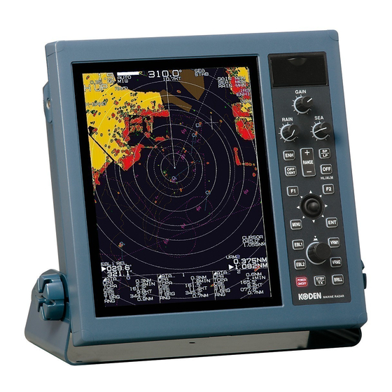
Koden MDC-2240 Operation Manual (129 pages)
Brand:
Koden
| Category:
Marine Radar
| Size: 1 MB
Table of Contents
Declaration of Conformity
2
Table of Contents
7
Chapter 1 Preface
15
About this Operation Manual
15
For Safe Usage
16
Disposal of Used Cell and this Device
18
Treatment of the Used Lithium Ion Cell
18
Disposal of this Device
18
Principal Features of this Device
18
In Case no Heading and Speed Signals Are Input from Navigation Equipment
19
Chapter 2 Function and Control Names
20
Radar Screen
20
Control Panel
21
Chapter 3 Basic Operation (for Control Panel)
25
Power On/Off
25
Power on
25
Power off
25
Change Brilliance of Display Unit (Screen and Control Panel)
25
Change Screen Brilliance
25
Change Brightness of Control Panel Dimmer
26
Transmission
26
Start Transmission
26
Stop Transmission
27
Change Range (Indicated Distance)
27
Adjust Receiver Gain (GAIN)
28
Reduce Sea Clutter (STC)
29
Enhance Target (W Clutter (FTC)
31
Measure Distance and Bearing of a Target
32
Measure Distance (VRM)
32
Measure Bearing (EBL)
33
Measure Distance/Bearing (Parallel Index Line)
34
Measure Distance and Bearing between Two Points (Offset)
37
Change Echo Color (DAY/NIGHT)
38
Remove the Heading Line
38
Relocate Own Ship Position (Off-Centering)
39
Select Display Mode
40
For H up (Head up Mode)
40
For C up (Course up Mode)
41
For N up (North up Mode)
41
For Relative Motion (RM) and True Motion (TM)
42
Reset True Motion
43
Use ATA/EPA
44
Manual Acquisition
44
Delete Target (Select and Delete)
45
Delete All Targets
45
Use Automatic Acquisition (up to 40 Targets Can be Acquired in Default)
45
Other Setting
48
EPA Operation Method
49
Update EPA
50
Types and Meaning of ATA/EPA Symbol
51
Use F (Function Key)
52
For Short Cut Menu
52
Position Data Output
53
Chapter 4 Menu Operations
54
How to See and Use Menu
54
Display Menu (Main Menu)
54
Delete Menu
54
Select Menu Item
54
Determine Setting
55
Display Detailed Menu
55
MARKER Menu
56
Display Range Rings
56
Set Bearing Mode (Relative/True Mode)
57
Marker Selection (MDC-2200 Only)
57
Designate Display Lines of Parallel Index
57
Designate Display Direction of Parallel Index
57
Designate Cross Cursor Display Method
58
VRM1 Setting of Range Unit
59
VRM2 Setting of Range Unit
59
PI Setting of Range Unit
59
Display Stern Marker
59
Setting of Cursor Shape
59
Tracking Cursor
59
HU Bearing Interlocking
60
Display VRM/EBL Intersection
60
Display Bearing Scale
60
Display Bearing in Numerical Value or with Symbol on the Bearing Scale
60
Select Bearing Display Location
60
Select Display Format
61
Use Blinking of Heading Line
61
Display Guard Line
61
Display Own Ship's Outline
61
Setup Own Ship's Profile (Cannot Use on Transmitting)
61
Display/Generate Own Ship's Profile
62
ECHO Menu
63
Select Display Mode
64
Display Trail
64
Select Trail Display Mode (Relative or True)
64
Select Trail Color (Blue or Red)
66
Select Trail Display Shape
66
Sustain Range
66
Time Keep
66
Switching of Base Input Sensor in True Motion (Course or Position)
66
Rel Mode
67
Trail Detection Level (1 to 6)
67
Interference Rejection (IR)
67
Display Target Stable Using Signal Processing
67
Switch over Day/Night Mode
68
Daytime Echo Color Selection (Change Daytime Mode Color)
68
Night Echo Color Selection (Change Night Mode Color)
68
Daytime Background Color Selection
68
Night Background Color Selection
68
Enlarge Cursor Position Image by Zooming Function
68
Reset True Motion
68
True Motion Reset Position
69
Fixed Image
69
Sector Scan
69
Designate Range Unit (NM, Km, Sm)
69
Designate Rotation Angle
69
Designate Rotation Speed
69
Full Screen Display
70
Off Center Position
70
NAV Menu
71
Select Stabilization Base (SEA/GND)
71
Set up Tide Bearing
71
Set up Tide Speed
71
Set up Vector Display Time
71
Set up Vector Display Mode
72
Use Navline
72
Select Block No. of Navline
72
Delete Navline by Designating Block no
72
Set up Detection Function
72
Input/Edit Navline Data
72
ALARM Menu
73
Use Guard Zone
73
Setup CPA
75
Setup TCPA
75
Setup ATA Buzzer Sound
75
Setup AIS Buzzer Sound
75
Setup Alarm 1 Detection Mode
77
Setup Alarm 1 Detection Level
77
Setup Alarm 1 Area Setting Method
77
Use Alarm 2
77
Select Alarm 2 Block Number
77
Delete Registered Data by Designating Block Number
78
Select Alarm 2 Detection Method
78
Setup Alarm 2 Detection Level
78
Input/Edit Alarm 2 Data
78
Delete Alarm Sound
79
ATA/EPA Menu
80
Select ATA Function or EPA Function
80
Manual Target Acquisition
80
Delete All Acquired Targets
81
Setting Method for Acquiring Number Manually
81
Auto Acquisition
81
Set up Target ID Display
81
ID Size
81
Select Target
81
EPA Update
81
Data Display Format
82
AIS Menu (Optional AIS Unit Required)
83
Activate AIS Display
83
Set up Target ID Display
83
Select Target
84
Setup Detection Area (Display Area Setup)
84
Setup Lost Target Display
84
Setup Sleep Ship Display
84
Setup Class B Target Display
84
Setup ATON Target Display
84
Setup SART Target Display
85
Setup BASE Target Display
85
Auto Acquisition Ring
85
Type and Meaning of AIS Symbols
85
CHART Menu
86
Display/Hide Chart
87
Insert Method of C-MAP Chart Card
87
Chart Card Removal
88
Setup Own Ship Track, ATA Target Track, and AIS Target Track
88
Setup Track Memory Interval
89
Delete Track
89
Setup Way Point/Route
89
Display Mark
89
Select Block Number for Mark Display
89
Delete Mark Data of Specified Block Number
90
Display Line from Own Ship Location to Mark
90
Select Display Mark Shape
90
Input Mark (Own Ship Position)
90
Mark Input/Delete (Cursor Position)
91
Input/Edit Mark (Latitude/Longitude Input)
91
All Marks Display
91
Select Chart
91
Detail Chart Display Setting
92
Accommodate Radar Image and Chart Display (Position Compensation)
92
Correct Latitude
92
Correct Longitude
92
Display Waypoint/Route ID
92
Display Flag Mark on Waypoint
92
Select COAST LINE/GPS BUOY
93
Using of COAST LINE
93
Using of GPS Buoys
93
DATADISP Menu
95
Upper Display Setting
95
Lower Display Area Background Color Setting
95
Setup DISP1 Display Item
96
Setup DISP2 Display Item
96
Setup DISP3 Display Item
96
Protect Cancel
96
STARTUP Menu
97
Tuning Method
97
Auto Tune Setting
97
Bearing Setting
97
Range Adjustment
97
STC Curve
98
Main Bang Suppression
98
10) F Key Setting
98
RAIN Key Setting
98
SEA Key Setting
98
GAIN Key Setting
98
I/O Menu
99
Heading Bearing
99
Ship Speed
99
Cog/Sog
99
Ground Stabilization Setting
99
Output (J4,J5)
99
Baud Rate
100
Input
100
SYSTEM Menu
101
Lang
101
Buzzer Sound
101
Buzzer Sound Frequency
101
Key Click
101
External Buzzer
101
PRESET Menu
102
Gain Manual
102
Manual STC Maximum
102
Manual STC Minimum
102
STC Curve
102
FTC Manual Selection
103
Main Bang Suppression
103
Target Level
103
ATA Performance
103
Video Mode
103
CONTRAST Menu
104
BITE Menu
105
Alarm Test
105
ATA Test
105
Total Operating Hours
105
Transmitting Hours
105
Panel Test
106
Monitor
106
Monitor No. Selection
106
ATA Diagnose
106
AIS Diagnose
106
Version
106
ANTENNA Menu
107
High Voltage
107
Mag Current
107
Mag Heater Voltage
107
Tune Voltage
107
Antenna Unit Type
107
Antenna Unit Communication Status
107
OPTION Menu
108
Inter-Switch
108
Antennal Location Designation
108
Echo Offset
108
Heading Offset
108
Antenna High Speed Rotation
108
Display Information
109
Ferry Mode
109
Length Unit
110
INITIAL Menu
111
Readout of Setup Items
111
Setup Save
111
External Load
112
External Save
112
System Program Load
112
ATA Program Load
112
AIS Program Load
112
Mark Load
112
Mark Save
112
Past Load
112
Past Save
112
Preset Load
113
Menu Configuration
114
Chapter 5 Specification and Configurations
118
Antenna
118
Display Unit
118
Configuration Items
119
Standard Configuration
119
Options
119
External View and Dimensions
120
Chapter 6 Principle of Radar System
122
What Is Radar System
122
Side Lobe
122
Beam Width
123
Characteristics of Radar Radio Wave
123
Target Hardness Reflected
123
Radar Shadow
124
False Image
124
Radar Interference
126
Chapter 7 Index
127
Advertisement
Koden MDC-2240 Installation Manual (123 pages)
Brand:
Koden
| Category:
Marine Radar
| Size: 1 MB
Table of Contents
Table of Contents
3
Preface
10
Precaution for Operation
10
Japan Domestic Criteria
10
Precautions for Maintenance
12
Caution against Residual High Voltage
12
Keep Inboard Power Source "Off
12
Caution against the Dust
12
Measures against Static Electricity
12
Chapter 1 Prior to Installation
13
Installation Precautions
13
Unpacking of Components
13
Appearance Verification of each Unit and Accessories
13
Selection of Location for Installation
13
Antenna Unit
13
Display Unit and Operation Panel
14
Cable Wiring and Interconnection
15
Antenna Unit
15
Display Unit
15
Chapter 2 System Configurations
16
Standard Configuration List
16
Spare Parts List
20
Installation Material List
20
Options
21
MDC-2240/2260/2210/2220 System Configuration
22
Chapter 3 Method of Installation
24
How to Install the Antenna-Scanner Unit
24
Installation of the Antenna-Scanner Unit
24
Mounting Antenna
25
Connecting the Cable
26
Interconnection Diagram of Cable
29
Installation of the Display Unit
30
Installation of MRD-101
30
Installation of MRD-102
34
Flush Mounting for MRD-102
37
Installing the Optional PCB
39
Installing the AIS PCB
39
Cable Connection to a Display Unit
40
Cable Connection for MRD-101
40
Cable Connection for MRD-102
41
Connecting the Display Unit to GPS Compass (KGC-1)
42
Connecting the KGC-1 and GTD-110/150 to a Display Unit
43
Connecting a Display Unit to KGC-1, GTD-110/150 and KBG-2/3
44
Connecting an External Buzzer and External Monitor
45
AIS Cable Connection
45
Cable Connection for Inter-Switch
46
Cable Connection Instructions for Cross-Over, Parallel and Independent Connection
46
Cable Connection for Slave Display Unit Used as a Monitor
47
Chapter 4 Setup after Installation
48
Setup of Menu Items at Installation
48
Adjustment of Transmitting Delay Time (Trigger Delay)
48
Display Bearing Adjustment
49
Adjustment of Automatic Tune
49
Assigning any Functions to Function Keys
50
Setup of Preset Menu Items
50
Setting Gain/Anti-Sea Clutter /STC Curve
50
Setup of Manual Gain
50
Setup of STC Curve
51
Setup of Manual STC Maximum Value
52
Setup of Manual STC Minimum Value
52
Setup of MBS Value (Main Bang Suppression)
53
Setup of ATA Threshold (ATA Target Level)
53
Changing the Radar Picture Expression (Video Mode)
53
Setting MAP Chart (at the Time of Using C-Map Card)
54
Display of C-Map Chart
54
Setup of Chart Details to be Displayed
54
Alignment of Chart Position
54
Setup of Serial Input
54
Using System Without Input Connection
54
Adjustment of Heading
55
Adjustment of Heading with Gyro I/F or GPS Compass Made by Other Manufacturer
55
Adjustment of Heading with KGC-1
55
Setup of Own-Ship Speed
55
Setup of Selected Bearing and Selected Speed Using Ground Stabilization
55
Selection of Signal for Ground Stabilization
55
Changing the Baud Rate of I/O Port J4, J5 and J6
56
Restriction of Signal Type of Specific Input Port
56
Controlling the Brilliance of the Marker, Radar Echoes, Etc. Independently
56
System Setup
57
Changing of Language from Japanese to English
57
Turning-Off the Alarm Buzzer
57
Change of Sound Volume of Buzzer
57
Turning-On/Off of Key-Click Sound
57
Turning-On/Off Alarm Sound for an External Alarm
57
Setup of Inter-Switch Functions
58
Crossover Connection (Please Refer to Figure 4.5)
58
Parallel (Dual) Connection
59
Independent Connection
60
Monitor Connection
61
Displaying Antenna Location on the Screen
62
Switching Antenna Rotation Speed, High/Low
62
Chapter 5 Detailed Setup and Additional Menu
63
Menu Configuration
64
Detailed Setup Items
68
Marker
68
Cursor and Bearing Cooperation
68
Cursor Shape
68
Stern Line
68
VRM1 Range Unit, VRM2 Range Unit and PI Range Unit
68
Bearing Display
69
Bearing Scale
69
Display Type
69
Head Line Blink
69
Position of Bearing Display
69
VRM/EBL Intersection
69
Guard Line
70
Own Ship's Profile Display
70
Echo
71
Keeping Range
71
Rel Mode
71
Time Keep
71
True Move
71
Detection Level
72
Position of True Motion Reset
72
Holding Picture
72
Sector Scan
72
Range Unit
72
Rotation Margin (Angle)
73
Rotation Speed
73
All Ppi
73
Off Centering Position
73
Navigation
74
Block Clear
74
Detection
74
Latitude and Longitude Input
74
Alarm
75
Detection Level
75
Area
75
Alarm2 Display
75
Block Number
76
Block Clear
76
Detection
76
Detection Level
76
Latitude and Longitude Input
76
Chart
77
Display Line from Own Ship Location to Mark
77
Mark Setup (Latitude and Longitude Input)
77
All Marks Display
77
Chart Selection
77
Chart Display Setup
77
Navigation Align Mode
78
Navigation Align Latitude
78
Navigation Align Longitude
78
Identification Display of Waypoint/Route
78
Display Flag Mark on Waypoint
78
Select Coast Line/Gps Buoy
78
Using of Coast Line
78
Using of GPS Buoys
79
Additional Menu
80
Input/Output
80
Heading
80
Speed
80
Cog/Sog
81
Ground Stabilization Mode
81
Latitude/Longitude
81
Output (J4, J5)
81
TLL out
81
Baud Rate
82
Input
82
Buzzer Frequency
83
Buzzer Sound
83
Contrast
83
External Buzzer
83
Key Click
83
Lang
83
Preset
83
System
83
Alarm Test
84
ATA Diagnosis
84
ATA Test
84
Monitor
84
Monitor Number Select
84
Panel Test
84
Self Diagnosis
84
Total Operation Hours
84
Total Transmission Hours
84
AIS Diagnosis
85
External Load
85
Initial
85
Readout of Setup Items
85
Setup Save
85
Version
85
AIS Program Load
86
ATA Program Load
86
External Save
86
Mark Load
86
Mark Save
86
Past Load
86
Past Save
86
Preset Load
86
System Program Load
86
Chapter 6 Troubleshooting and On-Board Repair
87
Provided Self Diagnostic Facilities
87
Error Display and Its Delete
87
Error Display List
88
Alarm Display List
89
Warning Display List
91
Status Indicator Lamp
92
Malfunction Diagnostics
93
Malfunction Detection Step
93
Malfunction Diagnostics Flow Chart
94
Initial Malfunction Diagnostics 1
94
Initial Malfunction Diagnostics 2
95
No Display
96
No Response from the Antenna Unit
97
Radar Picture Error
98
Data such as Heading, Speed, Latitude/Longitude Cannot be Received
99
Operation Panel Error
100
Antenna Unit Error
101
Other Errors
101
On-Board Repair
107
Replacement of Fuse
107
Replacement of Internal Battery
108
Chapter 7 Maintenance
109
Regular Service and Cleaning up
109
Monthly Inspection
109
Annual Inspection
109
Chapter 8 Input/Output Data
111
Input Data
111
Priority of Received Data
116
Details of ATA Tracking Data Output
116
Details of the Radar Data Output
117
Own Ship Data
117
Radar System Data
117
Interface Specification
118
Serial Data Input/Output Specification
118
External Buzzer and External Monitor Signal Specification
119
Koden MDC-2240 Specifications (2 pages)
MDC-2200/2500 series 12-inch / 15-inch Color LCD Marine Radar
Brand:
Koden
| Category:
Marine Radar
| Size: 0 MB
Advertisement
Koden MDC-2240 Quick Start Manual (2 pages)
Brand:
Koden
| Category:
Marine Radar
| Size: 2 MB
Advertisement
Related Products
Koden MDC-2200 series
Koden MDC2260
Koden MDC2220
Koden MDC2210
Koden MDC-2500 series
Koden MDC2560
Koden MDC-2004BB
Koden MDC-2060BB
Koden MDC-2010BB
Koden MDC-2041A
Koden Categories
Marine Radar
Marine Equipment
GPS
Sonar
Monitor
More Koden Manuals
Login
Sign In
OR
Sign in with Facebook
Sign in with Google
Upload manual
Upload from disk
Upload from URL