Sign In
Upload
Manuals
Brands
Kikusui Manuals
Test Equipment
TOS3200
Kikusui TOS3200 Manuals
Manuals and User Guides for Kikusui TOS3200. We have
3
Kikusui TOS3200 manuals available for free PDF download: Operation Manual, User Manual, Interface Manual
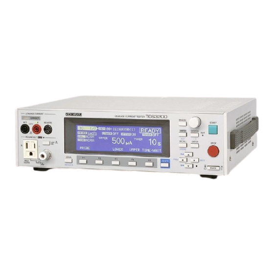
Kikusui TOS3200 Operation Manual (208 pages)
Leakage Current Tester
Brand:
Kikusui
| Category:
Test Equipment
| Size: 11.66 MB
Table of Contents
Use of Operation Manual
2
Safety Symbols
3
Notations Used in this Manual
3
Safety Precautions
4
Measurement Category
5
Table of Contents
6
Contents
6
Contents by Objectives
12
Front Panel
14
Rear Panel
16
General Description
17
Product Overview
18
Features
18
Options
20
Rack Mounting Option
20
Test Probe
20
Multi Outlet
21
Installation and Preparation
23
Checking the Package Contents
24
Precautions Concerning Installation Location
25
Using the Stand
26
Precautions for Moving the Product
26
Connecting the Power Cord
27
Connecting the Power Cord for the TOS3200
28
Connecting the Power Cord for the EUT
28
Turning the Power on
29
Turning the POWER Switch on
29
Turning the POWER Switch off
30
Panel Control Basics
31
Screen Configuration
32
Panel Control
34
Switching the Screen
34
Selecting Items
34
Entering Data
35
Adjusting the Screen Brightness
36
Key Lock
36
Selecting the Operation Mode
37
Single Tests (TC/PCC/METER)
37
Program Tests (AUTO)
37
Panel Memory
38
Storing to the Test Conditions
39
Recalling from the Test Conditions
39
TC and PCC Tests
41
Connecting the EUT
42
Using the Output on the Front Panel
42
Using the Terminal Block on the Rear Panel
42
Using the Optional Multi Outlet (OT01-TOS)
43
Checking the EUT Operation
44
Connecting the Test Lead (TL21-TOS)
45
Using the Flat Probe (FP01-TOS)
48
Using the Optional Test Probe (HP21-TOS)
49
Measurement Check
49
Judgment System
50
Validity of the Lower Reference
50
Test Wait Time and Judgment
51
Setting Test Conditions of the TC Measurement
52
Setup Items of TC1/2
52
Setup Items of TC1/2 (LOWER / UPPER / TIMER / WAIT)
54
Setup Items of TC2/2 (NTWK / MODE / RANGE)
55
Setting Test Conditions of the PCC Measurement
56
Setup Items of PCC1/2 (POL / COND)
56
Setup Items of PCC1/2 (LOWER / UPPER / TIMER / WAIT)
58
Setup Items of PCC2/2 (MODE / RANGE)
59
Setting Additional Test Conditions
60
Maximum Value Hold Function of the Measured Current (MEAS MODE)
60
Hold Time of the PASS Judgment (PASS HOLD)
60
Measured Current Conversion Display (CONV)
61
Buzzer Volume (BUZ VOL)
61
Starting the Test
62
When the Test Starts
62
Switching to Expanded Display
64
Displaying the Voltage between the Measurement Network Reference Points
64
Unable to Start the Test
65
Stopping the Test
66
Aborting the Test
66
When the Test Ends
66
Storing the Test Result
66
Releasing the Judgment Result
66
Storing the Test Results
67
Displaying the Test Results
68
Deleting the Stored Data
68
Meter Mode Measurement
69
Connecting the EUT
70
Constructing the Connection Circuit
70
Connecting the Test Lead (TL21-TOS)
71
Measuring in Meter Mode
72
Maximum Value Hold Function of the Measured Current (MEAS MODE)
72
SELV Detection Function
73
Setup Items of METER2/2 (NTWK / MODE / RANGE)
73
Program Test
75
Program Tests
76
Limitations on the Test Conditions in the Steps
77
Interval Time
77
Creating Sequence Programs
78
Inserting a Step in a New Program
78
Inserting a Step in an Existing Program
79
Deleting a Step
79
Setup Items of AUTO1/2
80
Setup Items of AUTO2/2 (Common to All Steps)
82
Sequence Program Editing Procedure
83
Entering the Edit Screen
83
Setting Items Common to the Program (All Steps)
84
Setting Step 00
84
Setting Step 01
85
Exiting from the Edit Screen
85
Setting Additional Test Conditions
86
Maximum Value Hold Function of the Measured Current (MEAS MODE)
86
Hold Time of the PASS Judgment (PASS HOLD)
86
Measured Current Conversion Display (CONV)
87
Buzzer Volume (BUZ VOL)
87
Power Supply to the EUT During the Interval Time (LINE BRK (AUTO))
88
Starting the Test
88
When a Test Starts
88
Unable to Start the Test
90
Stopping the Test
91
Aborting the Test
91
When the Test Ends
91
Program Test Judgment
91
Storing the Test Result
92
Releasing the Judgment Result
92
Storing the Test Results
93
Displaying the Test Results
94
Deleting the Stored Data
94
External Control
95
SIGNAL I/O Connector
96
SIGNAL I/O Specifications
96
Internal Construction
98
Application Examples of Input Signal
98
Application Examples of Output Signal
99
Starting the Test
99
Recalling the Panel Memory and Sequence Program
100
Remote Control
101
Remote Control Overview
102
VISA Library
103
Using the RS232C Interface
104
Using the GPIB Interface
107
Using the USB Interface
109
Overview of Messages
110
SCPI Command Syntax
110
Parameters
112
Command Description in this Manual
114
IEEE488.2 Common Commands
115
Selecting the Operation Mode
118
Setting the TC Measurement and PCC Measurement
118
Setting the Connection Destination of the Measurement Terminal (TC Measurement Only)
118
Setting the Power Line Polarity
119
Setting the Single Fault Mode
119
Setting the Lower Reference
120
Setting the Upper Reference
120
Setting the Test Time and Test Wait Time
121
Setting the Measurement Network (TC Measurement Only)
123
Setting the Measurement Mode
123
Setting the Measurement Range
124
Querying the Settings
124
Saving and Recalling from the Panel Memory
125
Executing the Test (Trigger Function)
126
Saving and Querying the Test Result
130
Querying the Judgment Result (Common to All Tests)
130
Saving the Result
130
Querying the Result
131
Deleting the Test Results
132
Setting the Program Test
133
Setting the Meter Mode Measurement
138
Setting the Measurement Network (Current Measurement Only)
138
Setting the Measurement Mode
138
Setting the Measurement Range (Current Measurement Only)
139
Querying the Settings
139
Querying the Measured Value
140
Querying the Measured Current Flowing through Measurement Terminals a and B
140
Querying the Measured Voltage between the Measurement Network Reference Points
140
Querying the Measured Voltage between Measurement Terminals a and B (Voltage Measurement Only)
141
Clearing the Maximum Measured Value
142
Voltage, Current, and Power of the EUT
142
Various Settings
144
Holding the Maximum Measured Current
144
Pass Judgment Hold Time
144
Converting Measured Current Based on the Specified Line Voltage
144
Setting the Safety Extra Low Voltage (SELV)
145
Setting the Buzzer Volume
145
Setting the Screen Brightness
146
Setting the Time
146
Turning the Power Line to the EUT On/Off
147
Showing/Hiding Communication Errors
147
Releasing the Protection Status
147
Other Settings
148
Status Register and Status Report Function
150
IEEE488.2 Register Model
152
Status Byte Register
152
Event Status Register
153
SCPI Register Model
154
Operation Status Register
154
Questionable Status Register
156
Preset Status
157
Tutorial
158
TC Measurement/Pcc Measurement (MANUAL TEST)
158
Program Test (AUTO TEST)
159
Meter Mode Measurement
160
Maintenance
161
Test Lead Check
162
Measurement Check
162
Time Settings and Calibration Management
164
Calibration
165
Replacing the Fuse
166
Replacing the Backup Battery
166
Specifications
167
Measurement Items, Measurement Mode, and Measurement Network
168
Current Measurement Section*1
168
Judgment Function
170
Voltage Measurement between a and B
171
Timer, Test Function, and Memory
171
Other Functions
172
Interface
173
General
174
Outline Drawing
175
Measurement Network (NTWK)
176
A Glossary
177
Appendix
177
B Four Principal Tests for Evaluating the Safety of Electrical and
177
Withstanding Voltage Test
181
Insulation Resistance Test
182
Earth Continuity Test
183
Leakage Current Test
184
C a List of Messages
186
D a List of Errors
192
Command Errors
192
Execution Errors
193
Query Errors
194
E Processing Time of Main
195
Commands
195
A List of Default Settings
196
Initializing the TOS3200
196
Default Values of the Panel Memory
198
G System Settings
200
Setup Items of SYSTEM1/5
200
Setup Items of SYSTEM2/5
201
Setup Items of SYSTEM3/5
202
Setup Items of SYSTEM4/5
202
Setup Items of SYSTEM5/5
203
H Protection Function
204
Troubleshooting
205
Advertisement
Kikusui TOS3200 User Manual (130 pages)
Leakage Current Tester
Brand:
Kikusui
| Category:
Test Equipment
| Size: 4.47 MB
Table of Contents
About the TOS3200 Manuals
2
Safety Symbols
3
Notations Used in this Manual
3
Safety Precautions
4
Measurement Category
5
Table of Contents
6
Contents
6
Contents by Objectives
10
Front Panel
12
Rear Panel
14
General Description
15
Product Overview
16
Features
16
Options
18
Rack Mounting Option
18
Test Probe
18
Multi Outlet
19
Installation and Preparation
21
Checking the Package Contents
22
Precautions Concerning Installation Location
23
Using the Stand
24
Precautions for Moving the Product
24
Connecting the Power Cord
25
Connecting the Power Cord for the TOS3200
26
Connecting the Power Cord for the EUT
26
Turning the Power on
27
Turning the POWER Switch on
27
Turning the POWER Switch off
28
Panel Control Basics
29
Screen Configuration
30
Panel Control
32
Switching the Screen
32
Selecting Items
32
Entering Data
33
Adjusting the Screen Brightness
34
Key Lock
34
Selecting the Operation Mode
35
Single Tests (TC/PCC/METER)
35
Program Tests (AUTO)
35
Panel Memory
36
Storing to the Test Conditions
37
Recalling from the Test Conditions
37
TC and PCC Tests
39
Connecting the EUT
40
Using the Output on the Front Panel
40
Using the Terminal Block on the Rear Panel
40
Using the Optional Multi Outlet (OT01-TOS)
41
Checking the EUT Operation
42
Connecting the Test Lead (TL21-TOS)
43
Using the Flat Probe (FP01-TOS)
46
Using the Optional Test Probe (HP21-TOS)
47
Measurement Check
47
Judgment System
48
Validity of the Lower Reference
48
Test Wait Time and Judgment
49
Setting Test Conditions of the TC Measurement
50
Setup Items of TC1/2
50
Setup Items of TC1/2 (LOWER / UPPER / TIMER / WAIT)
52
Setup Items of TC2/2 (NTWK / MODE / RANGE)
53
Setting Test Conditions of the PCC Measurement
54
Setup Items of PCC1/2 (POL / COND)
54
Setup Items of PCC1/2 (LOWER / UPPER / TIMER / WAIT)
56
Setup Items of PCC2/2 (MODE / RANGE)
57
Setting Additional Test Conditions
58
Maximum Value Hold Function of the Measured Current (MEAS MODE)
58
Hold Time of the PASS Judgment (PASS HOLD)
58
Measured Current Conversion Display (CONV)
59
Buzzer Volume (BUZ VOL)
59
Starting the Test
60
When the Test Starts
60
Switching to Expanded Display
62
Displaying the Voltage between the Measurement Network Reference Points
62
Unable to Start the Test
63
Stopping the Test
64
Aborting the Test
64
When the Test Ends
64
Storing the Test Result
64
Releasing the Judgment Result
64
Storing the Test Results
65
Displaying the Test Results
66
Deleting the Stored Data
66
Meter Mode Measurement
67
Connecting the EUT
68
Constructing the Connection Circuit
68
Connecting the Test Lead (TL21-TOS)
69
Measuring in Meter Mode
70
Maximum Value Hold Function of the Measured Current (MEAS MODE)
70
SELV Detection Function
71
Setup Items of METER2/2 (NTWK / MODE / RANGE)
71
Program Test
73
Program Tests
74
Limitations on the Test Conditions in the Steps
75
Interval Time
75
Creating Sequence Programs
76
Inserting a Step in a New Program
76
Inserting a Step in an Existing Program
77
Deleting a Step
77
Setup Items of AUTO1/2
78
Setup Items of AUTO2/2 (Common to All Steps)
80
Sequence Program Editing Procedure
81
Entering the Edit Screen
81
Setting Items Common to the Program (All Steps)
82
Setting Step 00
82
Setting Step 01
83
Exiting from the Edit Screen
83
Setting Additional Test Conditions
84
Maximum Value Hold Function of the Measured Current (MEAS MODE)
84
Hold Time of the PASS Judgment (PASS HOLD)
84
Measured Current Conversion Display (CONV)
85
Buzzer Volume (BUZ VOL)
85
Power Supply to the EUT During the Interval Time (LINE BRK (AUTO))
86
Starting the Test
86
When a Test Starts
86
Unable to Start the Test
88
Stopping the Test
89
Aborting the Test
89
When the Test Ends
89
Program Test Judgment
89
Storing the Test Result
90
Releasing the Judgment Result
90
Storing the Test Results
91
Displaying the Test Results
92
Deleting the Stored Data
92
External Control
93
SIGNAL I/O Connector
94
SIGNAL I/O Specifications
94
Internal Construction
96
Application Examples of Input Signal
96
Application Examples of Output Signal
97
Starting the Test
97
Recalling the Panel Memory and Sequence Program
98
Maintenance
99
Test Lead Check
100
Measurement Check
100
Time Settings and Calibration Management
102
Calibration
103
Replacing the Fuse
104
Replacing the Backup Battery
104
Specifications
105
Measurement Items, Measurement Mode, and Measurement Network
106
Current Measurement Section*1
106
Judgment Function
108
Voltage Measurement between a and B
109
Timer, Test Function, and Memory
109
Other Functions
110
Interface
111
General
112
Outline Drawing
113
Measurement Network (NTWK)
114
Appendix
115
A a List of Default Settings
115
Initializing the TOS3200
116
Default Values of the Panel Memory
118
B System Settings
120
Setup Items of SYSTEM1/5
120
Setup Items of SYSTEM2/5
121
Setup Items of SYSTEM3/5
122
Setup Items of SYSTEM4/5
122
Setup Items of SYSTEM5/5
123
C Protection Function
124
D Troubleshooting
125
Index
127
Kikusui TOS3200 Interface Manual (84 pages)
Leakage Current Tester
Brand:
Kikusui
| Category:
Test Equipment
| Size: 1.35 MB
Table of Contents
About the TOS3200 Manuals
2
Notations Used in this Manual
2
Table of Contents
3
Contents
3
Selecting the Interface
5
Remote Control Overview
6
VISA Library
7
Using the RS232C Interface
8
Using the GPIB Interface
11
Using the USB Interface
12
SCPI Language Overview
13
Overview of Messages
14
SCPI Command Syntax
14
Command Syntax
15
Parameters
17
Command Reference
19
Command Description in this Manual
20
IEEE488.2 Common Commands
21
Selecting the Operation Mode
24
Setting the TC Measurement and PCC Measurement
24
Setting the Connection Destination of the Measurement Terminal (TC Measurement Only)
24
Setting the Power Line Polarity
25
Setting the Single Fault Mode
25
Setting the Lower Reference
26
Setting the Upper Reference
26
Setting the Test Time and Test Wait Time
27
Setting the Measurement Network (TC Measurement Only)
29
Setting the Measurement Mode
29
Setting the Measurement Range
30
Querying the Settings
30
Saving and Recalling from the Panel Memory
31
Executing the Test (Trigger Function)
32
Saving and Querying the Test Result
37
Querying the Judgment Result (Common to All Tests)
37
Saving the Result
37
Querying the Result
38
Deleting the Test Results
39
Setting the Program Test
40
Setting the Meter Mode Measurement
45
Setting the Measurement Network (Current Measurement Only)
45
Setting the Measurement Mode
45
Setting the Measurement Range (Current Measurement Only)
46
Querying the Settings
46
Querying the Measured Value
47
Querying the Measured Current Flowing through Measurement Terminals a and B
47
Querying the Measured Voltage between the Measurement Network Reference Points
47
Querying the Measured Voltage between Measurement Terminals a and B (Volt- Age Measurement Only)
48
Clearing the Maximum Measured Value
48
Voltage, Current, and Power of the EUT
49
Various Settings
50
Holding the Maximum Measured Current
50
Pass Judgment Hold Time
50
Converting Measured Current Based on the Specified Line Voltage
50
Setting the Safety Extra Low Voltage (SELV)
51
Setting the Buzzer Volume
51
Setting the Screen Brightness
52
Setting the Time
52
Turning the Power Line to the EUT On/Off
53
Showing/Hiding Communication Errors
53
Releasing the Protection Status
53
Other Settings
54
Status Register and Status Report Function
56
IEEE488.2 Register Model
58
Status Byte Register
58
Event Status Register
59
SCPI Register Model
60
Operation Status Register
60
Questionable Status Register
62
Preset Status
63
Tutorial
64
TC Measurement/Pcc Measurement (MANUAL TEST)
64
Program Test (AUTO TEST)
65
Meter Mode Measurement
66
A a List of Messages
67
B a List of Errors
74
Command Errors
74
Execution Errors
75
Query Errors
76
C Processing Time of Main
77
Commands
77
D a List of Default Settings
78
Initializing the TOS3200
78
Default Values of the Panel Memory
80
Index
82
Advertisement
Advertisement
Related Products
Kikusui TOS5101
Kikusui TOS5050
Kikusui TOS5051
Kikusui tos6200
Kikusui TOS6200A
Kikusui TOS6210
Kikusui TOS9200
Kikusui TOS8030
Kikusui TOS5050A
Kikusui TOS5051A
Kikusui Categories
Power Supply
Test Equipment
Measuring Instruments
Controller
Remote Control
More Kikusui Manuals
Login
Sign In
OR
Sign in with Facebook
Sign in with Google
Upload manual
Upload from disk
Upload from URL