Sign In
Upload
Manuals
Brands
Keysight Technologies Manuals
Test Equipment
U1453A
Keysight Technologies U1453A Manuals
Manuals and User Guides for Keysight Technologies U1453A. We have
3
Keysight Technologies U1453A manuals available for free PDF download: User Manual, Service Manual
Keysight Technologies U1453A User Manual (163 pages)
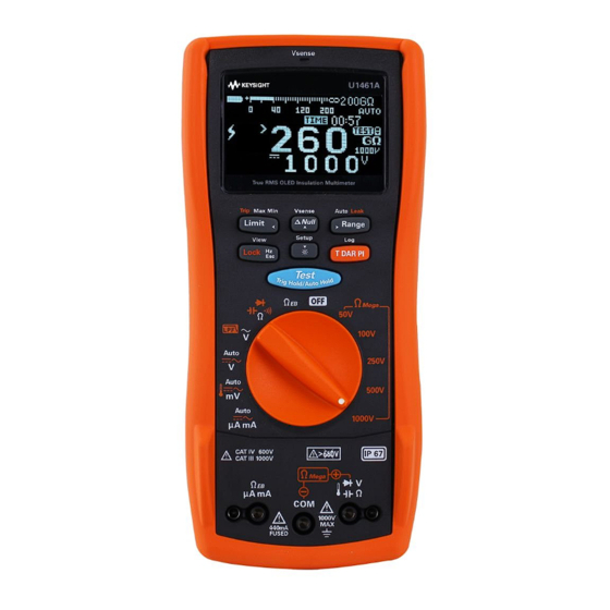
Insulation Multimeter/Insulation Tester
Brand:
Keysight Technologies
| Category:
Multimeter
| Size: 4 MB
Table of Contents
Safety Symbols
3
Safety Considerations
4
Measurement Category
6
Environmental Conditions
7
Regulatory Markings
8
Waste Electrical and Electronic Equipment (WEEE) Directive 2002/96/EC
9
Product Category
9
Sales and Technical Support
9
Table of Contents
11
1 Introduction
20
About this Manual
20
Documentation Map
20
Safety Notes
20
Preparing Your Tester
21
Check the Shipment
21
Install or Change the Batteries
21
Turn on Your Tester
24
Select the Range
24
Adjust the Tilt Stand
25
Connect to the Handheld Meter Logger Software
26
Figure 1-1 Keysight Handheld Meter Logger Software
26
Connect the Bluetooth Adapter
27
Figure 1-2 Bluetooth Adapter Connection
27
Your Tester in Brief
28
Dimensions
28
Figure 1-3 Width Dimensions
28
Figure 1-4 Height and Depth Dimensions
29
Overview
30
Table 1-1 Front Panel Part Descriptions
30
Table 1-2 Rear Panel Parts
31
Rotary Switch
32
Table 1-3 U1461A/U1453A Rotary Switch Functions
32
Keypad
35
Table 1-4 U1461A/U1453A Keypad Functions
38
Display Screen
39
Figure 1-5 Display Screen Allocation Example
39
Table 1-5 General Annunciators
40
Figure 1-6 Analog Bar Graph Example
45
Table 1-6 Measurement Units Display
45
Table 1-7 Analog Bar Graph Display Counts/Bar
46
Input Terminals
47
Figure 1-7 Connecting the Remote Switch Probe
47
Table 1-8 Terminal Connections for Different Measuring
47
Cleaning Your Tester
48
Additional Features
49
Automatic Power-Off
49
OLED Auto DIM Function
49
Change the OLED Brightness
49
Hazardous Voltage Indication
50
Power-On Options
50
Table 1-9 Power-On Options
50
2 Making Measurements
52
Insulation Resistance Test
52
Figure 2-1 Insulation Resistance Test Example
53
Using the Remote Switch Probe
54
Locking the Test
55
Figure 2-2 T Operation
56
Timed (T) Insulation Resistance/Earth-Bond Resistance Test
56
Figure 2-3 DAR Operation
57
Measuring the Dielectric Absorption Ratio (DAR)
57
Figure 2-4 PI Operation
58
Measuring the Polarization Index (PI)
58
Performing Leakage Current Trip Tests
59
Viewing the Leakage Current
59
Figure 2-5 TRIP Operation
60
Performing Stepped Voltage Trip Tests
61
Figure 2-6 Scan Signal
62
Figure 2-7 SCAN TRIP Operation
63
Figure 2-8 Ramp Signal
64
Figure 2-9 RAMP TRIP Operation
65
Changing the Insulation Resistance Test Voltage
66
Table 2-1 Rotary Switch Position for Insulation Resistance Tests .52 Table 2-2 User Test Voltage Range for Insulation Resistance
66
Earth-Bond Resistance Test
67
Table 2-3 Earth-Bond Resistance Test Position
67
Figure 2-10 Earth-Bond Resistance Test Example
68
Measuring AC or DC Voltage
70
Table 2-4 AC and DC Voltage Measurement Positions
70
Figure 2-11 AC or DC Voltage Measurement Example
71
Auto AC or DC Signal Identification
72
Figure 2-12 AC Voltage with LPF Measurement Example
73
Using the LPF (Low Pass Filter) Feature for AC Signals
73
Enabling the LPF in the Setup
75
Figure 2-13 Enabling the Low-Pass Filter
75
Measuring AC or DC Current
76
Table 2-5 AC and DC Current Measurement Positions
76
Figure 2-14 AC or DC Current Measurement Example
77
Scale of 4-20 Ma or 0-20 Ma
78
Table 2-6 % Scale Measurement Range
78
Measuring Frequency
79
Table 2-7 Measurement Positions Allowing Frequency
79
Figure 2-15 Definition of Frequency
80
Measuring Duty Cycle and Pulse Width
81
Measuring Resistance
82
Table 2-8 Resistance Measurement Position
82
Figure 2-16 Resistance Measurement Example
83
Continuity Test
84
Table 2-9 Continuity Test Position
84
Figure 2-17 Continuity Test Example
85
Diode Test
86
Table 2-10 Diode Test Position
86
Figure 2-18 Forward-Bias Diode Test Example
87
Figure 2-19 Reverse-Bias Diode Test Example
88
Table 2-11 Auto-Diode Voltage Thresholds
89
Using the Auto-Diode Feature
89
Figure 2-20 Auto-Diode Operation
90
Measuring Capacitance
91
Table 2-12 Capacitance Measurement Position
91
Figure 2-21 Capacitance Measurement Example
92
Viewing the Cable Length Value
93
Measuring Temperature
94
Table 2-13 Temperature Measurement Position
94
Figure 2-22 Surface Temperature Measurement Example
96
3 Tester Features
99
Non-Contact AC Voltage Detection (Vsense)
100
Figure 3-1 Detecting AC Voltage Example
101
Making Relative Measurements (Null)
102
Capturing Maximum and Minimum Values (Max Min)
103
Freezing the Display (Trighold and Autohold)
105
Performing Limit Comparisons (Limit)
106
Table 3-1 Hi/Lo Default Settling Values
106
Recording Measurement Data (Log)
108
Table 3-2 Log Maximum Capacity
108
Performing Interval Logs (AUTO)
109
Performing Manual Logs (HAND)
109
Performing Event Logs (TRIG)
110
Table 3-3 Event Log Trigger Conditions
111
Reviewing Previously Recorded Data (View)
113
4 Setup Options
115
Using the Setup Menu
116
Table 4-1 Setup Menu Key Functions
116
Editing Numerical Values
117
Setup Menu Summary
118
Table 4-2 Setup Menu Item Descriptions
118
Setup Menu Items
125
Menu 1
125
Changing the Variation Count
125
Changing the Recording Option
126
Changing the Sample Interval Duration
126
Changing the Data Update Rate
127
Enabling Smooth Mode
128
Menu 2
129
Menu 3
131
Menu 4
135
Menu 5
139
Menu 6
141
Menu 7
145
Menu 8
149
Menu 9
150
Menu 10
154
Menu 11
158
5 Characteristics and Specifications
161
Advertisement
Keysight Technologies U1453A Service Manual (59 pages)
Insulation Testers and Insulation Multimeter, U1450 Series
Brand:
Keysight Technologies
| Category:
Test Equipment
| Size: 2 MB
Table of Contents
Declaration of Conformity
2
Safety Information
2
Safety Symbols
3
Safety Considerations
4
Emc Compliance
6
Safety Compliance
6
Environmental Conditions
6
Regulatory Markings
7
Waste Electrical and Electronic Equipment (WEEE) Directive 2002/96/EC
8
Product Category
8
Sales and Technical Support
8
Table of Contents
9
Calibration Error Codes
15
Performance Verification Tests
15
Recommended Test Equipment
15
1 Calibration Procedures
16
Calibration Overview
16
Closed-Case Calibration
16
Keysight Calibration Services
16
Calibration Interval
16
Adjustment Is Recommended
17
Recommended Test Equipment
18
Table 1-1 Table
18
Calibration Process
19
Test Considerations
20
Performance Verification Tests
21
Performance Verification Tests for U1452A/U1452AT/U1451A
21
Table 1-5 Table
21
Table 1-7 Table
22
Performance Verification Tests for U1461A/U1453A
25
Performance Verification Tests for Models U1461A/U1453A
25
Calibration Security
31
Unsecuring the Instrument for Calibration
32
To Unsecure the Instrument from the Front Panel
32
To Change the Calibration Security Code
33
To Reset the Calibration Security Code to Its Factory Default
33
Using the Front Panel for Adjustments
35
Adjustment Considerations
35
Valid Adjustment Input Values (U1452A/U1452AT/U1451A)
36
Adjustment Input Values (U1452A/U1452AT/ U1451A)
37
Valid Adjustment Input Values (U1453A)
38
Adjustment Input Values (U1453A)
39
Valid Adjustment Input Values (U1461A)
42
Adjustment Procedure
46
Non-Contact Voltage (NCV) Calibration
47
Exiting the Adjustment Mode
48
Calibration Count
49
Calibration Error Codes
50
2 Service and Maintenance
52
Troubleshooting
52
Operating Checklist
52
Fuse Replacement
53
Returning the Instrument for Service
55
Replaceable Parts
56
To Order Replaceable Parts
56
Types of Service Available
57
Extended Service Contracts
57
Obtaining Repair Service (Worldwide)
58
Keysight Technologies U1453A Service Manual (64 pages)
Insulation Testers and Insulation Multimeter
Brand:
Keysight Technologies
| Category:
Multimeter
| Size: 1 MB
Table of Contents
Safety Symbols
5
Safety Considerations
6
Environmental Conditions
8
Table of Contents
13
1 Calibration Procedures
19
Calibration Overview
20
Closed-Case Calibration
20
Keysight Calibration Services
20
Calibration Interval
20
Adjustment Is Recommended
21
Recommended Test Equipment
22
Table 1-1 Recommended Test Equipment
22
Calibration Process
23
Test Considerations
24
Performance Verification Tests
25
Performance Verification Tests for U1452A/U1452AT/U1451A
25
Table 1-2 Performance Verification Tests (U1452A/U1452AT/U1451A)
25
Performance Verification Tests for U1461A/U1453A
29
Table 1-3 Performance Verification Tests for Models U1461A/U1453A
29
Calibration Security
35
Unsecuring the Instrument for Calibration
36
To Unsecure the Instrument from the Front Panel
36
To Change the Calibration Security Code
37
To Reset the Calibration Security Code to Its Factory Default
37
Using the Front Panel for Adjustments
39
Adjustment Considerations
39
Valid Adjustment Input Values (U1452A/U1452AT/U1451A)
40
Table 1-4 Adjustment Input Values (U1452A/U1452AT/U1451A)
40
Valid Adjustment Input Values (U1453A)
42
Table 1-5 Adjustment Input Values (U1453A)
42
Valid Adjustment Input Values (U1461A)
46
Table 1-6 Adjustment Input Values (U1461A)
46
Adjustment Procedure
50
Non-Contact Voltage (NCV) Calibration
51
Exiting the Adjustment Mode
52
Calibration Count
53
Calibration Error Codes
54
Table 1-7 Calibration Error Codes
54
2 Service and Maintenance
55
Troubleshooting
56
Table 2-1 Operating Checklist
56
Fuse Replacement
57
Returning the Instrument for Service
59
Replaceable Parts
60
To Order Replaceable Parts
60
Types of Service Available
61
Extended Service Contracts
61
Obtaining Repair Service (Worldwide)
62
Advertisement
Advertisement
Related Products
Keysight Technologies U1461A
Keysight Technologies U1818A
Keysight Technologies U1818B
Keysight Technologies U1610/20A
Keysight Technologies U1610A
Keysight Technologies U1620A
Keysight Technologies U11645A
Keysight Technologies U3042AE12
Keysight Technologies U3020AS16
Keysight Technologies U3022AE10
Keysight Technologies Categories
Measuring Instruments
Test Equipment
Control Unit
Portable Generator
Power Supply
More Keysight Technologies Manuals
Login
Sign In
OR
Sign in with Facebook
Sign in with Google
Upload manual
Upload from disk
Upload from URL