Sign In
Upload
Manuals
Brands
Keysight Technologies Manuals
Cash Counter
53230A
Keysight Technologies 53230A Manuals
Manuals and User Guides for Keysight Technologies 53230A. We have
1
Keysight Technologies 53230A manual available for free PDF download: Service Manual
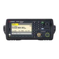
Keysight Technologies 53230A Service Manual (273 pages)
350 MHz Universal Frequency Counter/Timer
Brand:
Keysight Technologies
| Category:
Cash Counter
| Size: 10.04 MB
Table of Contents
Software Updates/Licenses
3
Assistance
4
Certification
4
Exclusive Remedies
4
Lithium Battery Recycling
5
Safety Symbols
5
Safety Information
6
General
6
Before Applying Power
6
Ground the Instrument
6
Fuses
6
Do Not Operate in an Explosive Atmosphere
7
Do Not Operate Near Flammable Liquids
7
Do Not Remove the Instrument Cover
7
Do Not Modify the Instrument
7
In Case of Damage
7
Cleaning the Instrument
7
Protection Limits
8
Installing the Instrument
9
Battery Operation
9
Waste Electrical and Electronic Equipment (WEEE) Directive
10
Product Category
10
Sales and Technical Support
10
Table of Contents
11
1 Performance Tests
24
Introduction
24
Chapter Overview
25
Performance Tests
26
Recommended Calibration Cycle
27
Internal Auto-Calibration
27
Equipment Required
28
Table 1-1 Recommended Test Equipment for Operational Verification and Performance Tests
28
Power-On Test
29
Self-Test (Q)
31
Run Internal Self-Test
31
Keysight 53210A/53220A/53230A Operational Verification
33
Figure 1-1 Operational Verification Setup for Keysight 53210A/220A/230A
33
Frequency Checks
33
Figure 1-2 Termination Check Setup
35
Termination Checks (Optional)
35
Keysight 53210A/53220A/53230A Complete Performance Tests
37
Table 1-2 the Keysight 53210A/53220A/53230A Performance
38
Test 1: (Q) Absolute Time Base
38
Figure 1-3 Absolute Timebase Test Setup
39
Figure 1-4 Test Setup for Channel 1/2 Frequency Accuracy Tests
43
Test 2: (Q) Frequency Accuracy - Channels 1 and 2
43
Keysight 53210A/53220A/53230A Performance Test Record (Tests 1 to 7)
48
Test 3: Single Period
49
Figure 1-5 Test Setup for Single Period
50
Test 4: (Q) Pulse Width
55
Figure 1-6 Pulse Width Test Setup
56
Test 5: (Q) Time Interval
60
Figure 1-7 Time Interval (Channel 1 to 2) Test Setup
61
(6 Ghz Microwave Channel)
65
Test 6A: (Q) Frequency Accuracy - Channel 2/3, Option 106
65
Figure 1-8 Option 106 ( 6 Ghz ) Microwave Channel 2/3 Test
66
(15 Ghz Microwave Channel)
71
Test 6B: (Q) Frequency Accuracy - Channel 2/3, Option 115
71
Figure 1-9 Option 115 ( 15 Ghz ) Microwave Channel 2/3 Test
72
Test 7A: (Q) Pulse Burst Frequency - 53230A Channel 3 Option 150 with Option 106
77
Figure 1-10 Option 106/150 Microwave Channel 3 Test Setup
78
Test 7C: (Q) Pulse Burst Frequency - 53230A Channel 3 Option 150 with Option 115
83
Figure 1-11 Option 115/150 Microwave Channel 3 Test Setup
84
Keysight 53210A/53220A/53230A Operational Verification and Performance Test Record
89
Keysight 53210A/53220A/53230A Performance Test Record (Tests 1 to 7)
90
2 Service
99
Introduction
100
Returning the Counter to Keysight Technologies for Service
100
About the Keysight 53210A/53220A/53230A Calibration Menu
100
The Keysight 53210A/53220A/53230A Calibration Procedures
100
Pre-Troubleshooting Information
100
Troubleshooting Information
100
Figure 2-1 the Front Panel at a Glance
101
Figure 2-2 Front Panel Display
102
Returning the Instrument to Keysight Technologies for Service
104
Operating Checklist
104
Is the Instrument Inoperative
104
Does the Instrument Fail Self-Test
104
Types of Service Available
104
Extended Service Contracts
104
Obtaining Repair Service (Worldwide)
105
To Provide Repair Information
106
To Pack in the Original Packaging Materials
107
To Pack in Commercially Available Materials
107
Warranty
108
About the Keysight 53210A/53220A/53230A Calibration Menu
109
Overview of the Keysight 53210A/53220A/53230A Calibration Menu
109
To Get Help with the Calibration Menu Functions
111
Figure 2-3 Calibration Procedure Summary
112
To View the Calibration Menu and Security Status from the Counter Front Panel
113
To Lock the Counter against Calibration
114
To Unlock the Counter for Calibration
116
To Change to a New Security Code
117
The Keysight 53210A/53220A/53230A Calibration Procedures
118
Equipment Required
118
Table 2-1 Recommended Test Equipment for Calibration
118
Determine the Counter Firmware Version
119
Figure 2-4 Information Screen
120
Calibration Cycle
121
Calibration String
121
Internal Reference Oscillator Calibration
121
Figure 2-5 Oscillator Calibration Setup
122
Summary of Oscillator Calibration Procedure
126
Remote Oscillator Calibration Summary
126
Voltage Calibration (Internal Dacs)
127
Figure 2-6 DC Voltage Source and DMM Connections
130
Option 106 Microwave Channel Frequency Calibration
133
Table 2-2 Option 106 Calibration Frequencies and Power Levels
137
Option 115 Microwave Channel Frequency Calibration
140
Figure 2-7 Microwave Source Connection to Channel
141
Figure 2-8 Microwave Source Connection to Channel 3
141
Table 2-3 Option 115 Calibration Frequencies and Power Levels
145
Internal Auto-Calibration
147
To View the Calibration Count
150
Resetting the Security Code to a Null
151
Pre-Troubleshooting Information
152
Safety Considerations
152
Recommended Test Equipment
153
Table 2-4 Recommended Equipment for Test and Troubleshooting
153
Repair Considerations
154
After Service Considerations
155
Table 2-5 Keysight 53210A/53220A/53230A Assembly Identification
156
Figure 2-9 Counter Top Internal View
158
Figure 2-10 Bottom Internal View
159
Troubleshooting the Counter
160
Power Supply Check
160
Unit Fails Self-Test
160
Unit Is Inoperative
160
Figure 2-11 Ac Power Supply Testpoint Locations on the Motherboard Assembly (Top View, Internal Battery Removed, Test Points Visible.)
162
Table 2-6 DC Power Supply Voltages
163
Checking the Battery and Battery Charger
164
Figure 2-12 Battery Folded in the Service Position
165
Figure 2-13 Test Button and Charge Indicator
166
Performing the Counter Self-Test
169
To Determine the Counter Firmware Version
170
Reseat the Boards
172
Re-Run the Counter Self Test
173
Error Messages
174
Command Errors (-100
174
Execution Errors (-200
174
Hardware Errors (-240, -241, -250
175
Device-Specific Errors (-300
176
Calibration Errors (700
177
Query Errors (-400
177
Self-Test Errors (901
178
3 Replacing Assemblies
182
Introduction
182
Tools Required
183
Do this First
183
Electrostatic Discharge
184
To Remove the Cover and Rear Bezel
185
Figure 3-1 Handle Removal
185
Figure 3-2 Rear Bezel and Cover Removal
186
To Remove the Internal DC Battery Assembly (Option 300)
187
Figure 3-3 Battery Assembly Temporary Position for Service or Removal
188
To Remove the GPIB Assembly
189
Figure 3-4 Top View of Counter Showing GPIB Assembly
189
To Remove a 6.0 Ghz or 15.0 Ghz Microwave Channel Assembly (Options 106/115)
190
Re-Installing the Microwave Channel Assembly
190
To Remove a 6.0 Ghz or 15.0 Ghz Microwave Channel Assembly (Options 106/ 115)
190
Figure 3-5 Front Flange Resting on Plastic Tab
191
To Remove the Processor Board
193
Figure 3-6 Processor PC Board
193
To Remove the Front Panel Assembly
194
Figure 3-7 Front Rubber Bumper Removal
194
Figure 3-8 Front Panel Removal
195
To Remove the Display Assembly from the Front Panel
197
To Remove the Motherboard
198
To Remove the AC Power Supply Assembly
199
4 Retrofitting Options
202
Introduction
202
Tools Required
202
To Retrofit the 53220A/53230A Channel 3 Input, 6.0 Ghz (Option 106) or 15.0 Ghz (Option 115) Plus Front Panel Option
202
Do this First
203
To Retrofit Ultra-High Stability Timebase (Option 010)
204
To Retrofit the GPIB Connector
205
GPIB Connector Parts (P/N 53200U-400)
205
Preliminary Steps
205
GPIB Connector Installation Procedure
206
To Retrofit the Internal Battery DC Power (Option 300)
207
Option 300 DC Power Input Assembly Parts
207
Preliminary Steps
207
Battery Assembly Installation Procedure
208
Figure 4-1 Connector Locking Tab
208
Figure 4-2 Jumper Cable Installed
209
Figure 4-3 Digital and Y-Cables
210
Figure 4-4 Test Button and Charge Indicator
210
Figure 4-5 Battery Assembly Connectors
211
Figure 4-6 Battery Assembly Held by Three Small Tabs
212
To Retrofit the 53210A (Channel 1) or 53220A/53230A (Channels 1/2) Rear Panel Inputs (Option 201)
213
Option 201 Rear Panel Channel 1/2 Parts
213
Preliminary Steps
213
Channels 1/2 Rear Panel Retrofit Procedure
215
Figure 4-7 Option 201 Rear Input Channels 1 and 2
215
To Retrofit the 53210A Channel 2 Front Panel Input (Option 106 or Option 115, Plus Front Panel Option 202)
217
Option 106/115 Channel 2 Parts
217
Option 202 Front Panel Channel 2 Parts
217
Preliminary Steps
218
Figure 4-8 53210A Channel 2 Front Panel Option 106/202
219
Channel 2 Front Panel Retrofit Procedure (53210A)
220
Figure 4-9 Processor Printed Circuit Board
220
Figure 4-10 T20 TORX Screw on Motherboard
221
Figure 4-11 Connector-Adapter Installation
222
Figure 4-12 Semi-Rigid Cable Position
223
Figure 4-13 Front Flange Resting on Plastic Tab
225
To Retrofit the 53210A Channel 2 Rear Panel Input, 6.0 Ghz (Option 106) or 15.0 Ghz (Option 115) Plus Rear Panel Option
227
Option 106/115 Channel 2 Parts
227
Option 203 Rear Panel Channel 2 Parts
227
Preliminary Steps
228
Figure 4-14 53210A Channel 2 Rear Panel Option
229
Channel 2 Rear Panel Retrofit Procedure (53210A)
230
Figure 4-15 Channel 2 Assembly Installed on Top of the Motherboard, with the SMA Edge Connector Pointing Toward the Rear of the Counter
230
Option 202 Front Panel Channel 3 Parts
232
Preliminary Steps
233
Front Panel Installation Procedure (Option 202 Only)
235
Figure 4-18 T20 TORX Screw on Motherboard
236
Figure 4-19 Connector-Adapter Parts
238
Figure 4-20 Semi-Rigid Cable Position
239
To Retrofit the 53220A/53230A Channel 3 Input, 6.0 Ghz (Option 106) or 15.0 Ghz (Option 115) Plus Rear Panel Option
242
Option 203 Rear Panel Channel 3 Parts
242
Preliminary Steps
243
Figure 4-21 53220A/53230A Rear Panel Option 106/203
244
Figure 4-22 Channel 3 Assembly Installed on Top of the Motherboard, with the Female SMA Edge Connector Pointing Toward the Rear
245
Rear Panel Installation Procedure (Option 203 Only)
245
To Retrofit Option 150 (Pulse Microwave Measurements) for the 53230A
247
Retrofitting Procedure
247
5 Replaceable Parts
249
Introduction
250
Contacting Keysight Technologies How to Order a Part Replaceable Parts
250
Contacting Keysight Technologies
251
By Telephone (in the United States)
251
For Mail Correspondence, Use the Address below
251
How to Order a Part
252
Parts Identification
252
Replaceable Parts
254
Table 5-1 Table of Replaceable Parts
254
Figure 5-1 Keysight 53210A/53220A/53230A Counters, Top View (Cover Off)
257
Figure 5-2 Keysight 53210A/53220A/53230A Counters, Bottom View (Cover Off)
258
6 Backdating
260
Introduction
260
Serial Numbers
260
Table 6-1 Instruments this Guide Directly Applies to
260
Backdating Firmware
262
To Determine the Counter Firmware Version
262
Figure 6-1 Information Screen
263
Procedure Changes
264
Information Concerning Option 106 "Microwave Input", FW Rev (27.0)
264
Figure 6-2 Microwave Source Connection to Channel
265
Advertisement
Advertisement
Related Products
Keysight Technologies 53210A
Keysight Technologies 53220A
Keysight Technologies 53150A
Keysight Technologies 53151A
Keysight Technologies 53152A
Keysight Technologies 53147A
Keysight Technologies 53149A
Keysight Technologies 53148A
Keysight Technologies Option 503
Keysight Technologies Option 513
Keysight Technologies Categories
Measuring Instruments
Test Equipment
Control Unit
Portable Generator
Power Supply
More Keysight Technologies Manuals
Login
Sign In
OR
Sign in with Facebook
Sign in with Google
Upload manual
Upload from disk
Upload from URL