
Related Manuals for Keysight Technologies 53210A

Summary of Contents for Keysight Technologies 53210A
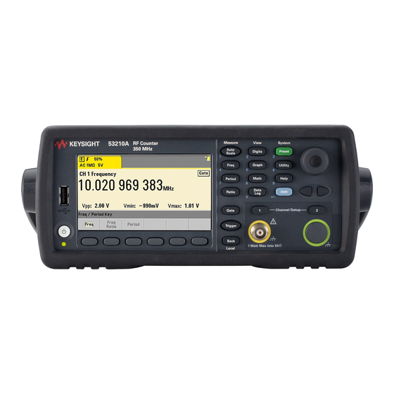
- Page 1 Keysight 53210A/53220A/ 53230A 350 MHz Universal Frequency Counter/Timer Assembly Level Service Guide...
- Page 2 FAR 27.401 or DFAR could result in personal injury or death. 227.7103-5 (c), as applicable in any Do not proceed beyond a WARNING technical data. notice until the indicated conditions are fully understood and met. Keysight 53210A/53220A/53230A Assembly Level Service Guide...
-
Page 3: Software Updates/Licenses
This product utilizes Microsoft Windows CE. Keysight highly recommends that all Windows-based computers connected to Windows CE instruments utilize current anti-virus software. For more information, go to the product page at: www.keysight.com/find/53210A www.keysight.com/find/53220A www.keysight.com/find/53230A Keysight 53210A/53220A/53230A Assembly Level Service Guide... -
Page 4: Assistance
Certification Keysight Technologies certifies that this product met its published specifications at time of shipment from the factory. Keysight Technologies further certifies that its calibration measurements are traceable to the United States National Institute of Standards and Technology, to the extent allowed by the Institute's calibration facility, and to the calibration facilities of other International Standards Organization members. -
Page 5: Lithium Battery Recycling
Lithium Battery Recycling The 53210A/53220A/53230A counters contain a 3 V “coin cell” lithium battery. Keysight recommends that this battery be replaced every year at the instrument’s 1-year calibration interval. Replacement procedures are provided in the 53210A/ 53220A/53230A Service Guide. Option 300 provides battery operation of the 53210A/53220A/53230A using a 12 lithium battery. -
Page 6: Safety Information
(grounding) conductor or disconnection of the protective earth terminal will cause a potential shock hazard that could result in personal injury. Fuses The Keysight 53210A/53220A/53230A is provided with an internal line fuse appropriate for the line voltages listed on the instrument. This fuse is not user accessible. -
Page 7: Do Not Operate In An Explosive Atmosphere
Cleaning the instrument Clean the outside of the instrument with a soft, lint-free, slightly-dampened cloth. Do not use detergents or chemical solvents. Keysight 53210A/53220A/53230A Assembly Level Service Guide... -
Page 8: Protection Limits
Do not connect the input channels of the 53210A/53220A/53230A to AC WARNING line-voltage mains or to circuits derived from AC mains. The instrument must be used in CAT I (isolated from mains) applications only. Do not use in other IEC Measurement Category (CAT II, CAT III, or CAT IV) applications. -
Page 9: Installing The Instrument
Instrument ventilation is through the sides and rear. Do not obstruct the ventilation holes in any of these locations. Battery operation When operating the 53210A or 53220A under battery power (Option 300), failure to observe the following warnings may result in damage to the instrument, electric shock, and serious personal injury:... -
Page 10: Waste Electrical And Electronic Equipment (Weee) Directive
To contact Keysight for sales and technical support, refer to the support links on the following Keysight websites: – www.keysight.com/find/53210A www.keysight.com/find/53220A www.keysight.com/find/53220A (product-specific information and support, software and documentation updates) – www.keysight.com/find/assist (worldwide contact information for repair and service) Keysight 53210A/53220A/53230A Assembly Level Service Guide... -
Page 11: Table Of Contents
..........29 Keysight 53210A/53220A/53230A Assembly Level Service Guide... - Page 12 ..........100 Returning the counter to Keysight Technologies for service .
- Page 13 ..........108 About the Keysight 53210A/53220A/53230A Calibration Menu .
- Page 14 ......194 To remove the display assembly from the front panel ..197 Keysight 53210A/53220A/53230A Assembly Level Service Guide...
- Page 15 Channel 2 front panel retrofit procedure (53210A) ... .220 To Retrofit the 53210A Channel 2 Rear Panel Input, 6.0 GHz (Option 106) or 15.0 GHz (Option 115) plus Rear Panel Option 203 .
- Page 16 Rev (27.0) ......... . . 264 Keysight 53210A/53220A/53230A Assembly Level Service Guide...
- Page 17 ........272 Keysight 53210A/53220A/53230A Assembly Level Service Guide...
- Page 18 THIS PAGE HAS BEEN INTENTIONALLY LEFT BLANK. Keysight 53210A/53220A/53230A Assembly Level Service Guide...
- Page 19 ....... . .188 Figure 3-4 Top view of counter showing GPIB assembly ..189 Keysight 53210A/53220A/53230A Assembly Level Service Guide...
- Page 20 Figure 4-7 Option 201 rear input channels 1 and 2 ..215 Figure 4-8 53210A channel 2 front panel Option 106/202 ..219 Figure 4-9 Processor printed circuit board .
- Page 21 .....254 Table 6-1 Instruments this guide directly applies to ..260 Keysight 53210A/53220A/53230A Assembly Level Service Guide...
- Page 22 THIS PAGE HAS BEEN INTENTIONALLY LEFT BLANK. Keysight 53210A/53220A/53230A Assembly Level Service Guide...
- Page 23 Counter/Timer Assembly Level Service Guide Performance Tests Introduction Power-On Test Self-Test (Q) Keysight 53210A/53220A/53230A Operational Verification Keysight 53210A/53220A/53230A Complete Performance Tests Keysight 53210A/53220A/53230A Operational Verification and Performance Test Record Keysight 53210A/53220A/53230A Performance Test Record (Tests 1 to 7) Verifying specifications.
-
Page 24: Performance Tests
Power-On Test – Self-Test (Q) – Keysight 53210A/53220A/53230A Operational Verification – Keysight 53210A/53220A/53230A Complete Performance Tests – Keysight 53210A/53220A/53230A Operational Verification and Performance Test Record – Keysight 53210A/53220A/53230A Performance Test Record (Tests 1 to 7) Keysight 53210A/53220A/53230A Assembly Level Service Guide... -
Page 25: Chapter Overview
The complete performance verification tests verify the specifications listed on the Keysight 53210A/53220A/53230A Product Reference CD-ROM as “Keysight 53210A/53220A/53230A Specifications.” All tests can be performed without accessing the inside of the instrument. The complete performance tests are recommended as acceptance tests upon initial receipt of your counter. They will also help you to become familiar with its performance and operation. -
Page 26: Performance Tests
– Ensure that ambient relative humidity is less than 80%. – See page 37 for warm-up considerations. – Keep the instrument cables as short as possible, consistent with the impedance requirements. Use only RG-58 or equivalent 50 Ω cable for measurements. Keysight 53210A/53220A/53230A Assembly Level Service Guide... -
Page 27: Recommended Calibration Cycle
AutoDigits OFF: [Digits] / (AutoDigits) / <Off> – The softkey menus shown in the test procedures represent the functionality of the 53230A. The softkey menus for the 53210A and 53220A may be different depending on the function selected. Recommended calibration cycle The counter requires periodic verification of operation. -
Page 28: Equipment Required
BNC(f) to banana plug (m) 10M4161 50 Ω coaxial cable with BNC(m) to BNC(m), 48 inches Keysight 10503A BNC connectors (5) 3.5mm cables (2) DC-18 GHz,matched pair Keysight 11500E Coaxial BNC tee connector Keysight 1250-0781 Keysight 53210A/53220A/53230A Assembly Level Service Guide... -
Page 29: Power-On Test
– The counter is now ready to measure frequency of a signal applied to CHANNEL 1 input as indicated by illumination of the Freq softkey and Channel 1 annunciator. An auto-cal is performed at power-on. (See “To run auto calibration:” NOTE page 148 for more information.) Keysight 53210A/53220A/53230A Assembly Level Service Guide... - Page 30 NOTE Counter” on page 160 of this service guide. 5 Mark Pass or Fail in the Keysight 53210A/53220A/53230A Power-ON Test Record, Test 1, at the end of this chapter. The power-on hardware initialization activities check the following circuits for NOTE operation: –...
-
Page 31: Self-Test (Q)
After turn-on, or at any time a reasonable operational status needs to be verified, the internal Self-Test can be run. Run internal self-test 1 Disconnect any input signal(s) from the counter. 2 Press the Utility key and then the Instr Setup softkey. Keysight 53210A/53220A/53230A Assembly Level Service Guide... - Page 32 If “Sel f-Test Failed” is displayed or any other failure is indicated, refer to the NOTE troubleshooting section in Chapter 2, "Service" page 4 Mark Pass or Fail in the “Keysight 53210A/53220A/53230A Performance Test Record (Tests 1 to 7)” on page 90. Keysight 53210A/53220A/53230A Assembly Level Service Guide...
-
Page 33: Keysight 53210A/53220A/53230A Operational Verification
Options"). If you are unfamiliar with the operation of the counter, you can review the “Keysight 53210A/53220A/53230A Quick Start Tutorial.” However, the procedures in this chapter are written so that little operational experience is necessary. The procedures should be followed in the order in which they appear. - Page 34 The remaining steps apply only to the Keysight 53220A and Keysight NOTE 53230A53230A since the Keysight 53210A does not have a second RF frequency input. 5 In the same way as for Channel 1, connect the Int Ref Out to the Channel 2 input connector (front or rear panel).
-
Page 35: Termination Checks (Optional)
(set DMM to appropriate Ohms range). On the DMM, use a dual-banana plug-to-BNC connector. Ch 1 Figure 1-2 Termination Check Setup 3 Press the Channel 1 key. – The LED turns on and the Channel 1 Setup softkeys are displayed: Keysight 53210A/53220A/53230A Assembly Level Service Guide... - Page 36 90. 10 Repeat steps 2 through 9 for RF Channel 2 for the Keysight 53220A/53230A counters ONLY, since the Keysight 53210A counter does not have a standard RF Channel 2. 11 Mark Pass or Fail in the Keysight 53220A/53230A Operational Verification Test...
-
Page 37: Keysight 53210A/53220A/53230A Complete Performance Tests
The following seven performance tests, when successful, verify that the counter meets the instrument specifications as provided on the CD ROM that came with your Keysight 53210A/53220A/53230A Counter. See also the information on running a ‘QUICK’ performance test on page 25. -
Page 38: Test 1: (Q) Absolute Time Base
[a] Other counter measurement functions are mathematically derived by the processor from the parameters verified by these performance tests. Test 1: (Q) Absolute time base This test uses the Keysight 53210A/53220A/53230A Frequency Counters to measure the absolute frequency of the internal 10 MHz clock. Equipment –... -
Page 39: Figure 1-3 Absolute Timebase Test Setup
– Channel 1 annunciator is lit. 3 Press the Trigger key. – The following softkeys are displayed: 4 Press and set: – Trigger Source: Manual – Wait For Trig is displayed. – Rdgs/Trigger: 100. Keysight 53210A/53220A/53230A Assembly Level Service Guide... - Page 40 8 Press the Frequency/Period key. – The following softkeys are displayed: Opt 150 – If Ad vanced is appears, press Auto to select Auto measurement mode. The 53210A does not have an Auto measurement mode. NOTE Keysight 53210A/53220A/53230A Assembly Level Service Guide...
- Page 41 – Level Setup / Input Level: 0.000 V – BW Limit: Off – Probe: None 11 Press the Math key. – The Math softkeys are displayed: 12 Press to set: – All Math: On Keysight 53210A/53220A/53230A Assembly Level Service Guide...
- Page 42 – 10 MHz ± 0.5 Hz (for Option 010 high stability timebase) 3 Record the ‘Mean’ test value, Test 1, in the “Keysight 53210A/53220A/53230A Performance Test Record (Tests 1 to 7)” on page 90. 4 Proceed to Test #2 or disconnect the test setup. Keysight 53210A/53220A/53230A Assembly Level Service Guide...
-
Page 43: Test 2: (Q) Frequency Accuracy - Channels 1 And 2
Trig In IS M 1 -A U S B L A N 9 0 V A M a x CG635 Signal Generator Ch 1 Figure 1-4 Test setup for channel 1/2 frequency accuracy tests Keysight 53210A/53220A/53230A Assembly Level Service Guide... - Page 44 – Ext Ref is shown in the upper right-hand corner of the display. – The following softkeys are displayed: *Opt 150 4 Press and set: – Measurement mode: Ad vanced / Auto The 53210A does not have an Auto measurement mode. NOTE Keysight 53210A/53220A/53230A Assembly Level Service Guide...
- Page 45 – Rdgs/Trigger: 100 9 Press the Gate key. – The Gate softkeys are displayed: 10 Press and set: – Gate src: Timed – Gate time: 10 mSec – Gate out: On – Polarity: Norm Keysight 53210A/53220A/53230A Assembly Level Service Guide...
- Page 46 – Level Setup / Auto Level: Off – Level Setup / Input Level: 0.000 V 13 Press the Math key. – The following softkeys are displayed: 14 Press and set: – All math: On Keysight 53210A/53220A/53230A Assembly Level Service Guide...
- Page 47 1 Press the Trigger key to manually trigger the counter. – Counter takes 100 readings and fills in Math functions. 2 Verify the ‘Mean’ is: – 10 MHz ± 100 mHz (for 53210A) – 10 MHz ± 10 mHz (for 53220A/53230A) 3 Verify the ‘Std Dev’ is less than: –...
-
Page 48: Keysight 53210A/53220A/53230A Performance Test Record (Tests 1 To 7)
Performance Tests 4 Record the ‘Mean’ and ‘Std Dev’, Test 2a, for Channel 1 (10 MHz), in the “Keysight 53210A/53220A/53230A Performance Test Record (Tests 1 to 7)” page 90. 5 Press the Reset Stats softkey. 6 Set CG635 output frequency to 115 MHz and repeat step 1. -
Page 49: Test 3: Single Period
Performance Tests Step 16 applies only to the 53220A and 53230A. The 53210A does not have a NOTE Channel 2 for RF frequencies. Also, selecting Channel 2 automatically resets the statistics. 17 Record the ‘Mean’ and ‘Std Dev’ for all three Channel 2 frequencies, Test 2b, Channel 2, in the “Keysight 53210A/53220A/53230A Performance Test Record... -
Page 50: Figure 1-5 Test Setup For Single Period
– Display shows: – Instrument has been preset. – Ext Ref is shown in the upper right-hand corner of the display. 3 On the Counter, press the Time Interval key. – The following softkeys are displayed: Keysight 53210A/53220A/53230A Assembly Level Service Guide... - Page 51 – The Channel 1 Setup menu softkeys are displayed. 7 Press and set: – Coupling: DC – Impedance: 50 Ω – Range: 5 V – BW Limit: Off 8 Press the Trigger key. – The trigger softkeys are displayed: Keysight 53210A/53220A/53230A Assembly Level Service Guide...
- Page 52 – Trig Delay: 0 Seconds – Rdgs/Trigger: 100 10 Press the Math key. – The following softkeys are displayed: 11 Press and set: – All Math: On 12 Press the Statistics softkey: – The Statistics softkeys are displayed: Keysight 53210A/53220A/53230A Assembly Level Service Guide...
- Page 53 Keysight 53220A/53230A Performance Test Record starting on page 5 Press the Reset Stats softkey. 6 Set the CG635 output frequency to 250 MHz. 7 Press the Trigger key. – Counter takes 100 readings and fills in Math functions. Keysight 53210A/53220A/53230A Assembly Level Service Guide...
- Page 54 13 Record the ‘Mean’ and ‘Std Dev’ for 1 MHz and 250 MHz, Channel 2, Test 3c and 3d, in the Keysight 53220A/53230A Performance Test Record starting on page 14 Press the Reset Stats softkey. 15 Proceed to Test #4 or disconnect the setup. Keysight 53210A/53220A/53230A Assembly Level Service Guide...
-
Page 55: Test 4: (Q) Pulse Width
Keysight 10503 BNC cables (3) – Keysight 15443A (SMA) cable or Keysight 11500E (3.5 mm) cable – Keysight 1250-1200 BNC(f)-to-SMA(m) adapter (2) 81134A setup – Output Level: 1 Vpp – Period: 66.6 nSec – Pulse Width: 5 nSec Keysight 53210A/53220A/53230A Assembly Level Service Guide... -
Page 56: Figure 1-6 Pulse Width Test Setup
2 Press the Preset key to preset the counter. – Display shows: – Instrument has been preset. – Ext Ref is shown in the upper right-hand corner of the display. 3 Press the Time Interval key. – The following softkeys are displayed: Keysight 53210A/53220A/53230A Assembly Level Service Guide... - Page 57 – Set noise rejection: Off 6 Press the Trigger key. Front panel display shows: 7 Press and set: – Source: Manual – Wait For Trig is displayed – Rdgs/Trigger: 100 – Trig Delay: 0 Seconds Keysight 53210A/53220A/53230A Assembly Level Service Guide...
- Page 58 – BW Limit: OFF 10 Press the Math key. – The following softkeys are displayed: 11 Press and set: – All math: On 12 Press the Statistics softkey: – The Statistics softkeys are displayed: Keysight 53210A/53220A/53230A Assembly Level Service Guide...
- Page 59 – 0.028 nSec (53230A) 4 Record the Mean and Standard Deviation for Channel 1, Test 4a, in the “Keysight 53210A/53220A/53230A Performance Test Record (Tests 1 to 7)” page 90. 5 Repeat steps 1 to 3 for Channel 2 (Test 4b). Be sure to do the Channel 2 setup first.
-
Page 60: Test 5: (Q) Time Interval
Performance Tests 6 Record the Mean and Standard Deviation for Channel 2, Test 4b, in the “Keysight 53210A/53220A/53230A Performance Test Record (Tests 1 to 7)” page 90. 7 Proceed to Test #5 or disconnect the test setup. Test 5: (Q) Time interval This test verifies the time interval specifications between Channel 1 and Channel 2. -
Page 61: Figure 1-7 Time Interval (Channel 1 To 2) Test Setup
– Instrument has been preset. – Ext Ref is shown in the upper right-hand corner of the display. 3 Press the Time Interval key. – The following softkeys are displayed: 4 Press the Time Interval softkey. Keysight 53210A/53220A/53230A Assembly Level Service Guide... - Page 62 – Noise Rej: Off 9 Press the Back key. 10 Press the Stop Ch Level softkey. 11 Press and set: – Slope: Pos – Auto Level: Off – Level: 0 V – Noise Rej: Off Keysight 53210A/53220A/53230A Assembly Level Service Guide...
- Page 63 – Source: Manual – Wait For Trig is displayed – Rdgs/Trigger: 100 – Trig Delay: 0 seconds 14 Press the Math key. – The following softkeys are displayed: 15 Press and set: – All Math: On Keysight 53210A/53220A/53230A Assembly Level Service Guide...
- Page 64 4 Record the Median and Standard Deviation, Test 5, in the “Keysight 53210A/ 53220A/53230A Performance Test Record (Tests 1 to 7)” on page 90. 5 Proceed to Test #6 or disconnect the test setup. Keysight 53210A/53220A/53230A Assembly Level Service Guide...
-
Page 65: Test 6A: (Q) Frequency Accuracy - Channel 2/3, Option 106
Performance Tests Test 6a: (Q) Frequency accuracy - channel 2/3, option 106 (6 GHz microwave channel) This test verifies the frequency accuracy of Option 106 Channel 2 (53210A) or Channel 3 (53220A/53230A) at two frequencies (100 MHz and 5.88 GHz). Equipment –... -
Page 66: Figure 1-8 Option 106 ( 6 Ghz ) Microwave Channel 2/3 Test
Figure 1-8 Option 106 ( 6 GHz ) microwave channel 2/3 test setup For the Keysight 53210A Counter, Option 106 is installed as Channel 2. For the NOTE Keysight 53220A and 53230A Counters, Option 106 is installed as Channel 3. For this procedure, “Channel 3”... - Page 67 – The Gate softkeys are displayed: 5 Press and set: – Gate Src: Timed – Gate Out: On – Gate Time: 10 mSec 6 Press the Trigger key. – The Trigger softkeys are displayed: Keysight 53210A/53220A/53230A Assembly Level Service Guide...
- Page 68 – Trig Delay: 0 seconds 8 Press the Math key. – The Math softkeys are displayed: 9 Press to set: – All Math: On 10 Press the Statistics softkey: – The Statistics softkeys are displayed: Keysight 53210A/53220A/53230A Assembly Level Service Guide...
- Page 69 1 Press the Trigger key. – The counter takes 100 readings and fills in the math functions. 2 Verify the ‘Mean’ is: – 100 MHz ± 1.000 Hz (53210A) – 100 MHz ± 100 mHz (53220A/53230A) 3 Verify the ‘Std Dev’ is less than: –...
- Page 70 7 Press the Trigger key. – The counter takes 100 readings and fills in the math functions. 8 Verify the ‘Mean’ is: – 5.88 GHz ± 58.800 Hz (53210A) – 5.88 GHz ± 5.880 Hz (53220A/53230A) 9 Verify the ‘Std Dev’ is less than: –...
-
Page 71: Test 6B: (Q) Frequency Accuracy - Channel 2/3, Option 115
Test 6b: (Q) Frequency accuracy - channel 2/3, option 115 (15 GHz microwave channel) This test verifies the frequency accuracy of Option 115 Channel 2 (53210A) or Channel 3 (53220A/53230A) at three frequencies (300 MHz, 3.1 GHz, and 15.0 GHz). -
Page 72: Figure 1-9 Option 115 ( 15 Ghz ) Microwave Channel 2/3 Test
Figure 1-9 Option 115 ( 15 GHz ) microwave channel 2/3 test setup For the Keysight 53210A Counter, Option 115 is installed as Channel 2. For the NOTE Keysight 53220A and 53230A Counters, Option 115 is installed as Channel 3. For this procedure, “Channel 3”... - Page 73 – The Gate softkeys are displayed: 5 Press and set: – Gate Src: Timed – Gate Out: On – Gate Time: 10 mSec 6 Press the Trigger key. – The Trigger softkeys are displayed: Keysight 53210A/53220A/53230A Assembly Level Service Guide...
- Page 74 – The Math softkeys are displayed: 9 Press to set: – All Math: On 10 Press the Statistics softkey: – The Statistics softkey menu is displayed: 11 Press to set: – Statistics: On – The display shows: Keysight 53210A/53220A/53230A Assembly Level Service Guide...
- Page 75 1 Press the Trigger key. – The counter takes 100 readings and fills in the math functions. 2 Verify the ‘Mean’ is: – 300 MHz ± 3.0 Hz (53210A) – 300 MHz ± 0.3 Hz (53220A/53230A) 3 Verify the ‘Std Dev’ is less than: –...
- Page 76 Performance Tests 8 Verify the ‘Mean’ is: – 3.1 GHz ± 31 Hz (53210A) – 3.1 GHz ± 3.1 Hz (53220A/53230A) 9 Verify the ‘Std Dev’ is less than: – 43.4 Hz (53210A) – 21.7 Hz (53220A) – 4.34 Hz (53230A) 10 Record the Mean and Standard Deviation for 3.1 GHz, Test 6b,...
-
Page 77: Test 7A: (Q) Pulse Burst Frequency - 53230A Channel 3 Option 150 With Option 106
– Keysight 1250-1250 N(M) to SMA(F) E8257D-520-UNW setup – Output Frequency: 6 GHz – Output Power: 0 dBm – Auto-Level Control: Off – Pulse Mode: On – Pulse Repetition Interval Period: 1 mSec – Pulse Width (Narrow): 200 nSec Keysight 53210A/53220A/53230A Assembly Level Service Guide... -
Page 78: Figure 1-10 Option 106/150 Microwave Channel 3 Test Setup
Signal Ch 3 Generator Figure 1-10 Option 106/150 microwave channel 3 test setup 2 Press the Preset key to preset the counter. 3 If needed, perform an Auto-Calibration. (Refer to “Internal auto-calibration” page 27.) Keysight 53210A/53220A/53230A Assembly Level Service Guide... - Page 79 There are no parameters to set for Channel 3 for this test. NOTE 5 Press the Freq period key. – The Freq/Period softkeys are displayed: 6 Press the Pulse/Burst softkey. – The Pulse/Burst menu softkeys are displayed: Keysight 53210A/53220A/53230A Assembly Level Service Guide...
- Page 80 – Source: Manual – Wait For Trig is displayed – Rdgs/Trigger: 100 – Trig Delay: 0 seconds 11 Press the Math key. – The Math softkeys are displayed: 12 Press to set: – All Math: On Keysight 53210A/53220A/53230A Assembly Level Service Guide...
- Page 81 14 Press to set: – Statistics: On – The display shows: Channel 3 pulse burst frequency test procedure 1 Press the Trigger key. – The counter takes 100 readings and fills in the math functions. Keysight 53210A/53220A/53230A Assembly Level Service Guide...
- Page 82 12 Record the Mean and Standard Deviation for Test 7b, in the “Keysight 53210A/ 53220A/53230A Performance Test Record (Tests 1 to 7)” on page 90. 13 Press the Reset Stats softkey. 14 Disconnect the test setup. Keysight 53210A/53220A/53230A Assembly Level Service Guide...
-
Page 83: Test 7C: (Q) Pulse Burst Frequency - 53230A Channel 3 Option 150 With Option 115
– Keysight 1250-1250 N(M) to SMA(F) E8257D-520-UNW setup – Output Frequency: 1.35 GHz – Output Power: -6 dBm – Auto-Level Control: Off – Pulse Mode: On – Pulse Repetition Interval Period: 1 mSec – Pulse Width (Narrow): 400 nSec Keysight 53210A/53220A/53230A Assembly Level Service Guide... -
Page 84: Figure 1-11 Option 115/150 Microwave Channel 3 Test Setup
2 Press the Preset key to preset the counter. 3 If needed, perform an auto-calibration. (Refer to “Internal auto-calibration” page 27.) 4 Press the Channel 3 input key. – Channel 3 is selected for test input. Keysight 53210A/53220A/53230A Assembly Level Service Guide... - Page 85 – The Pulse/Burst menu softkeys are displayed: 7 Press the Burst Freq softkey. – The Burst Freq menu softkeys are displayed: 8 Press to select: – dB Level: -6 – Narrow: On – Gate Auto: On Keysight 53210A/53220A/53230A Assembly Level Service Guide...
- Page 86 – Trig Delay: 0 seconds 11 Press the Math key. – The Math softkeys are displayed: 12 Press to set: – All Math: On 13 Press the Statistics softkey: – The Statistics softkeys are displayed: Keysight 53210A/53220A/53230A Assembly Level Service Guide...
- Page 87 – 338 kHz 4 Record the Mean and Standard Deviation for Test 7c, in the “Keysight 53210A/ 53220A/53230A Performance Test Record (Tests 1 to 7)” on page 90?. 5 Press the Reset Stats softkey. Keysight 53210A/53220A/53230A Assembly Level Service Guide...
- Page 88 12 Record the Mean and Standard Deviation for Test 7d, in the “Keysight 53210A/ 53220A/53230A Performance Test Record (Tests 1 to 7)” on page 90. 13 Press the Reset Stats softkey. 14 Disconnect the test setup. Keysight 53210A/53220A/53230A Assembly Level Service Guide...
-
Page 89: Keysight 53210A/53220A/53230A Operational Verification And Performance Test Record
Performance Tests Keysight 53210A/53220A/53230A Operational Verification and Performance Test Record Keysight Technologies Model 53210A/53220A/53230A Universal Counter Model Number: ______________________________ Serial Number: _________________________ Repair/Work Order No: ______________________ Test Performed By: _____________________________ Temperature: _______________________ Date: ______________________Relative Humidity: ______________________________________ Notes: ______________________________________________________________________________ Test Resul ts... -
Page 90: Keysight 53210A/53220A/53230A Performance Test Record (Tests 1 To 7)
349.999 996 500 MHz 350 MHz Test 350.000 003 500 MHz (only) ____________________ Record: Std Dev 10 MHz Test 115 MHz Test 140.000 mHz ____________________ 350 MHz Test 1 610.000 mHz ____________________ 4 900.000 mHz ____________________ Keysight 53210A/53220A/53230A Assembly Level Service Guide... - Page 91 349.999 999 650 MHz 350.000 000 350 MHz 350 MHz Test ____________________ Record: Std Dev 10 MHz Test 14.000 000 mHz 115 MHz Test ____________________ 161.000 000 mHz 350 MHz Test ____________________ 490.000 000 mHz ____________________ Keysight 53210A/53220A/53230A Assembly Level Service Guide...
- Page 92 349.999 999 650 MHz 350.000 000 350 MHz 350 MHz Test ____________________ Record: Std Dev 10 MHz Test 14.000 000 mHz 115 MHz Test ____________________ 161.000 000 mHz 350 MHz Test ____________________ 490.000 000 mHz ____________________ Keysight 53210A/53220A/53230A Assembly Level Service Guide...
- Page 93 .028 000 000 nSec Ch 1 - 250 MHz b. __________________ .028 000 000 nSec Ch 2 - 1 MHz c. __________________ .028 000 000 nSec Ch 2 - 250 MHz d. __________________ .028 000 000 nSec Keysight 53210A/53220A/53230A Assembly Level Service Guide...
- Page 94 5.400 000 000 nSec Record: Std Dev __________________ 0.140 000 000 nSec Ch 2 (53230A) Record: Mean 4.800 000 000 nSec __________________ 5.200 000 000 nSec Record: Std Dev __________________ 0.028 000 000 nSec Keysight 53210A/53220A/53230A Assembly Level Service Guide...
- Page 95 99.999 999 900 MHz __________________ 100.000 000 100 MHz 99.999 999 900 MHz __________________ 100.000 000 100 MHz 53210A Record: Std Dev 53220A __________________ 1 400.000 000 mHz 53230A __________________ 700.000 000 mHz __________________ 140.000 000 mHz Keysight 53210A/53220A/53230A Assembly Level Service Guide...
- Page 96 53230A 299.999 999 7 MHz __________________ 300.000 000 3 MHz 299.999 999 7 MHz __________________ 300.000 000 3 MHz 53210A Record: Std Dev 53220A __________________ 4.2 Hz 53230A __________________ 2.1 Hz __________________ 0.42 Hz Keysight 53210A/53220A/53230A Assembly Level Service Guide...
- Page 97 21 Hz Pulse Burst Record: Mean Frequency 5.994 000 000 GHz __________________ 6.006 000 000 GHz (6 GHz) Option 106 Option 150 Narrow Pulse Wid th Record: Std Dev 53230A (200 nSec) _____________________ 3.000 MHz Keysight 53210A/53220A/53230A Assembly Level Service Guide...
- Page 98 338 kHz Pulse Burst Record: Mean Frequency Option 115 1.349 979 200 GHz __________________ 1.350 020 800 GHz Option 150 (1.35 GHz) 53230A Wide Pulse Wid th Record: Std Dev (13 uSec) _____________________ 7.79 kHz Keysight 53210A/53220A/53230A Assembly Level Service Guide...
-
Page 99: Service
Keysight 53210A/53220A/53230A 350 MHz Universal Frequency Counter/Timer Assembly Level Service Guide Service Introduction Returning the Instrument to Keysight Technologies for Service About the Keysight 53210A/53220A/53230A Calibration Menu The Keysight 53210A/53220A/53230A Calibration Procedures Pre-Troubleshooting Information Troubleshooting the Counter Error Messages... -
Page 100: Introduction
Unless otherwise indicated, this manual applies to all serial numbers for the NOTE Keysight 53210A/53220A/53230A Counters. This chapter provides service information for your Keysight 53210A, 53220A, and 53230A Counters. It is divided into five major sections: Returning the counter to Keysight Technologies for service This section provides you with instructions on how to return the counter to Keysight for service. -
Page 101: Figure 2-1 The Front Panel At A Glance
2 On / Standby Switch 3 Menu Softkeys 4 Back / Local Key 5 Channel Input Connectors 6 Channel Input Keys 7 L-R / Cursor Keys 8 Knob 9 System Keys 10 View Keys 11 Measure Keys Keysight 53210A/53220A/53230A Assembly Level Service Guide... -
Page 102: Figure 2-2 Front Panel Display
A sample series of key depressions might be: [Utility] / (Cal AutoCal) / enter <code> / (Unlock Cal) If the counter is under warranty, refer to “Returning the Instrument to Keysight NOTE Technologies for Service” on page 104. Keysight 53210A/53220A/53230A Assembly Level Service Guide... - Page 103 These boards contain model number and serial number information that uniquely identifies a specific unit, and boards that are mismatched to the instrument may result in problems with performance, calibration, licensing, serviceability, importability/exportability or warranty. Keysight 53210A/53220A/53230A Assembly Level Service Guide...
-
Page 104: Returning The Instrument To Keysight Technologies For Service
Service Returning the Instrument to Keysight Technologies for Service Operating checklist Before returning your instrument to Keysight Technologies for service or repair, check the following items: Is the instrument inoperative? – Verify that the AC power cord is connected to the instrument and an AC outlet. -
Page 105: Obtaining Repair Service (Worldwide)
– www.keysight.com/find/assist Or contact your Keysight Technologies Representative. Before shipping your instrument, ask the Keysight Technologies Service Center to provide shipping instructions, including what components to ship. Keysight recommends that you retain the original shipping carton for use in such shipments. -
Page 106: To Provide Repair Information
Service To provide repair information If you are shipping the instrument to an Keysight Technologies office for service or repair, call your nearest Keysight Technologies Sales Office to make arrangements. Then tag and package the Keysight 53210A/53220A/53230A Counter for shipment. -
Page 107: To Pack In The Original Packaging Materials
– The shock-absorbing material should be 70 to 100 mm (3 to 4 inches) thick around all sides of the instrument to prevent movement inside the container. – Seal the shipping container securely. – Mark the shipping container FRAGILE. Keysight 53210A/53220A/53230A Assembly Level Service Guide... -
Page 108: Warranty
– In Europe: 31 20 547 2111 – In Japan: 0120–421–345 If you have questions relating to the operation of the Keysight 53210A, 53220A, or 53230A Counters, call 1-800-452-4844 in the United States, or contact your nearest Keysight Technologies Sales Office as shown at the front of this service guide. -
Page 109: About The Keysight 53210A/53220A/53230A Calibration Menu
Menu,” can be used as a reference. Your counter should be calibrated at least once each year to maintain specification accuracy. Overview of the Keysight 53210A/53220A/53230A calibration menu The Calibration menu is accessed by pressing the Utility key and then the Cal / AutoCal softkey. - Page 110 If the Self-Test passes, the calibration(s) may continue. If the counter fails the Self-Test, calibration should not be attempted until the counter is repaired and passes Self-Test. Refer to “Troubleshooting the Counter” on page 160. Keysight 53210A/53220A/53230A Assembly Level Service Guide...
-
Page 111: To Get Help With The Calibration Menu Functions
– how to calibrate – how to secure the calibration routines – how to change the security code – how to enter the Cal String Figure 2-3 for a summary of the front panel calibration procedures. NOTE Keysight 53210A/53220A/53230A Assembly Level Service Guide... -
Page 112: Figure 2-3 Calibration Procedure Summary
Press Perform Cal Step softkey. DONE: Press See Service DONE: Press Calibration See Service Calibration any key to Manual any key to Succeeded? Manual. continue Succeeded ? continue Figure 2-3 Calibration procedure summary Keysight 53210A/53220A/53230A Assembly Level Service Guide... -
Page 113: To View The Calibration Menu And Security Status From The Counter Front Panel
The Calibration String can not be entered from the front panel keys. It can only be entered/updated using the remote SCPI command: CALibration STRing. Refer to the Keysight 53210A/ 53220A/53230A SCPI Programmer’s Reference for details of the command format. -
Page 114: To Lock The Counter Against Calibration
2 The characters available to use for the security code are selectable by rotating the knob on the front panel for each character position in the code: – A to Z, underline character, ( _ ), and 0 to 9. Keysight 53210A/53220A/53230A Assembly Level Service Guide... - Page 115 – The data entry area and Secure Code areas change to all dash ( -- ) characters when the code is accepted. – The Lock Cal softkey changes to Unlock Cal. – The Cal Count is incremented only if a new secure code was entered. Keysight 53210A/53220A/53230A Assembly Level Service Guide...
-
Page 116: To Unlock The Counter For Calibration
2-2). – For example, if AT53210A was the security code set at the factory (for a 53210A Counter), then enter AT53210A into the data entry field. The code will repeat in the Secure Code line in the Calibrate Information screen. -
Page 117: To Change To A New Security Code
– The data entry area and Secure Code areas change to all dash ( -- ) characters when the code is accepted. – The Cal Count is incremented and the Lock Cal softkey changes to the Unlock Cal softkey. Keysight 53210A/53220A/53230A Assembly Level Service Guide... -
Page 118: The Keysight 53210A/53220A/53230A Calibration Procedures
Use an equivalent model number. Whenever possible, the counter should be calibrated with the instrument NOTE oriented in the same physical direction in which it will be used (i.e. flat, on one side, or front panel facing up). Keysight 53210A/53220A/53230A Assembly Level Service Guide... -
Page 119: Determine The Counter Firmware Version
2-4) is displayed that contains the following items: – Keysight Model Number – Instrument Serial Number – IP and GPIB addresses – Firmware Version (Format: x.xx - x.xx - xx - xx - xx) – Installed Options Keysight 53210A/53220A/53230A Assembly Level Service Guide... -
Page 120: Figure 2-4 Information Screen
After completing a new calibration of the counter, be sure to secure the stored NOTE calibration values by performing the procedure in the section titled “To lock the counter against calibration” on page 114. Keysight 53210A/53220A/53230A Assembly Level Service Guide... -
Page 121: Calibration Cycle
Service Calibration cycle The calibration cycle for the Keysight 53210A, 53220A, and 53230A Counters is 1-year. The counter should be calibrated at least once every 12 months to ensure specification accuracy. Calibration string: The Cal String on the Calibrate Information page is operator-modifiable and can be used to remotely enter any current or historical data/information up to 40 characters long. -
Page 122: Figure 2-5 Oscillator Calibration Setup
4 Connect the frequency source (Q or not Q output) to Channel 1 on the counter front panel. See Figure 2-5. CG 635 RF Signal Generator Figure 2-5 Oscillator calibration setup 5 Press the Utility key: – Display softkey annunciators show: Keysight 53210A/53220A/53230A Assembly Level Service Guide... - Page 123 It can only be entered/updated using the remote SCPI command: CALibration STRing. Refer to the Keysight 53210A/53220A/53230A SCPI Programmer’s Reference for details of the command format. – Secure Code displays either all dashes ( --- ) or an operator-entered security code that has not yet been accepted by the counter.
- Page 124 * Only displayed if Option 106 or Option 115 is installed. 11 Press the Oscil softkey. – Display softkey annunciators show: The data entry area will display the expected calibration frequency (10.000 NOTE MHz). Keysight 53210A/53220A/53230A Assembly Level Service Guide...
- Page 125 Service Center for information and help on sending the counter to Keysight for repair and/or calibration. If you are able to read the error message(s), consult “Error Messages” NOTE page 174 for what to do after receiving a specific calibration error message. Keysight 53210A/53220A/53230A Assembly Level Service Guide...
-
Page 126: Summary Of Oscillator Calibration Procedure
– For remote calibration, an Internal Reference Oscillator calibration is NOTE automatically selected (over internal DAC calibration) since the cal value of 10E6 is larger than the acceptable DAC voltage range. Keysight 53210A/53220A/53230A Assembly Level Service Guide... -
Page 127: Voltage Calibration (Internal Dacs)
MUST be within 1.0 milliVolt of the actual voltage source output. It is suggested that a BNC ‘T’ be connected to the power supply output to enable a DMM to measure the voltage that will be applied to the counter. Keysight 53210A/53220A/53230A Assembly Level Service Guide... - Page 128 Secure Code is updated; (4) the counter firmware is updated. It is not operator-modifiable and rolls over at (2 -1). Since the unit is calibrated several times during manufacture, the Cal Count will not be zero when shipped. Keysight 53210A/53220A/53230A Assembly Level Service Guide...
- Page 129 It can only be entered/updated using the remote SCPI command: CALibration STRing. Refer to the Keysight 53210A/53220A/53230A SCPI Programmer’s Reference for details of the command format. – Secure Code displays either all dashes ( --- ) or an operator-entered security code that has not yet been accepted by the counter.
-
Page 130: Figure 2-6 Dc Voltage Source And Dmm Connections
11 Press the Perform Cal Step softkey. – If the calibration step PASSES, after a few seconds the counter momentarily displays: – “Calibration step succeeded.” – The Cal Count on the screen will increment. Keysight 53210A/53220A/53230A Assembly Level Service Guide... - Page 131 (See website information on page 2 of this guide.) 16 If you are able to read the error message(s), consult the “Error Messages” page 174 for what to do after receiving a specific calibration error message. Keysight 53210A/53220A/53230A Assembly Level Service Guide...
- Page 132 For a remote internal DAC calibration, DAC Cal is automatically selected (over NOTE internal reference oscillator calibration) since the cal value of 4.096 is smaller than the acceptable reference oscillator frequency range. An AutoCal is performed automatically after this calibration is successfully NOTE completed. Keysight 53210A/53220A/53230A Assembly Level Service Guide...
-
Page 133: Option 106 Microwave Channel Frequency Calibration
The following procedure should be performed when Option 106 (6 GHz Microwave channel) with any Option 106 firmware revision other than FW Rev 27 is installed as Channel 2 in a 53210A or Channel 3 in a 53220A or 53230A. See Chapter 6, "Backdating"... - Page 134 Secure Code is updated; (4) the counter firmware is updated. It is not operator-modifiable and rolls over at (2 -1). Since the unit is calibrated several times during manufacture, the Cal Count will not be zero when shipped. Keysight 53210A/53220A/53230A Assembly Level Service Guide...
- Page 135 It can only be entered/updated using the remote SCPI command: CALibration STRing. Refer to the Keysight 53210A/53220A/53230A SCPI Programmer’s Reference for details of the command format. – Secure Code displays either all dashes ( --- ) or an operator-entered security code that has not yet been accepted by the counter.
- Page 136 13 Select the ‘output enable’ ON feature of the microwave source or reconnect the cable to the counter, as appropriate. 14 Use the front panel knob and left/right arrow keys to enter the value (500 MHz) as shown. Keysight 53210A/53220A/53230A Assembly Level Service Guide...
-
Page 137: Table 2-2 Option 106 Calibration Frequencies And Power Levels
+10 dBm 4500 MHz -27 dBm -4 dBm +10 dBm 5000 MHz -27 dBm -4 dBm +10 dBm 5250 MHz -27 dBm -4 dBm +10 dBm 5500 MHz -27 dBm -4 dBm +10 dBm Keysight 53210A/53220A/53230A Assembly Level Service Guide... - Page 138 Service Center for information and help on sending the counter to Keysight for repair and/or calibration. 21 If you are able to read the error message(s), consult “Error Messages” page 174 for what to do after receiving a specific calibration error message. Keysight 53210A/53220A/53230A Assembly Level Service Guide...
- Page 139 – 0 indicates the calibration PASSED. – Any value other than 0 indicates calibration FAILED. – Connect calibration source to channel 2 (53210A) or channel 3 (at 500 MHz, -27 dBm for Option 106). – Send command to calibrate: “CALibration:LEVel3? 500E6, -27”.
-
Page 140: Option 115 Microwave Channel Frequency Calibration
The following procedure should be performed when Option 115 (15 GHz Microwave channel) with any Option 115 firmware revision is installed as Channel 2 in a 53210A or Channel 3 in a 53220A or 53230A. 1 Press the following keys:... -
Page 141: Figure 2-7 Microwave Source Connection To Channel
-21 dBm. If the source has an ‘output enable’ feature, turn it OFF at first (for the zero-calibration procedure). 6 Connect the microwave frequency source to Channel 3 on the counter front panel. (Channel 2 for a 53210A.) See Figure 2-8. - Page 142 It can only be entered/updated using the remote SCPI command: CALibration STRing. Refer to the Keysight 53210A/53220A/53230A SCPI Programmer’s Reference for details of the command format. – Secure Code displays either all dashes ( --- ) or an operator-entered security code that has not yet been accepted by the counter.
- Page 143 If your microwave source does not have an ‘output enable/disable’ feature, NOTE temporarily disconnect the cable from the microwave input channel until after the zero-calibration is performed. 14 Press the Perform Zero-Cal softkey to perform zero-calibration. – Display momentarily shows: Keysight 53210A/53220A/53230A Assembly Level Service Guide...
- Page 144 – The Cal Count on the screen will increment. 19 Repeat steps 16 to 18 using each of the calibration frequencies and power levels in Table 2-3 (total of 36 steps). For each calibration step, set the source frequency and power accordingly. Keysight 53210A/53220A/53230A Assembly Level Service Guide...
-
Page 145: Table 2-3 Option 115 Calibration Frequencies And Power Levels
Cal Count, remain unchanged. 22 To check for error messages, refer to the Summary of Option 115 remote microwave calibration: below for information on how to read the error message(s) from a remote computer. Keysight 53210A/53220A/53230A Assembly Level Service Guide... - Page 146 – 0 means OFF or unlocked. – Send zero-calibration command (one-time only): – Use: “CALibration:LEVel3? 0,0” for 53220A/53230A. – Use: “CALibration:LEVel2? 0,0” for 53210A. – Retrieve query result: – 0 indicates the calibration PASSED. – Any value other than 0 indicates calibration FAILED.
-
Page 147: Internal Auto-Calibration
Service – Connect calibration source to channel 2 (53210A) or channel 3 (53220A or 53230A) at 300 MHz, -21 dBm for Option 115. – Send command to calibrate: “CALibration:LEVel3? 300E6, -21”. – Use “CALibration:LEVel2? 300E6, -21” for 53210A. – Retrieve query result: –... - Page 148 – If the calibration is successful, the screen displays “Auto Calibration succeeded”. – Cal Count is not updated, but the calibration constants ARE updated. – If any one of the calibration routines fails, the screen displays “Auto Calibration failed”. Keysight 53210A/53220A/53230A Assembly Level Service Guide...
- Page 149 – Retrieve query result: – 0 indicates the auto-calibration PASSED. – Any value other than 0 indicates auto-calibration FAILED. – If the retrieved value is non-zero, read error queue: SYSTem:ERRor? – Read errors until no more errors. Keysight 53210A/53220A/53230A Assembly Level Service Guide...
-
Page 150: To View The Calibration Count
Secure Code is updated; (4) the counter firmware is updated. It is not operator-modifiable and rolls over at (2 -1). Since the unit is calibrated several times during manufacture, the Cal Count will not be zero when shipped. Keysight 53210A/53220A/53230A Assembly Level Service Guide... -
Page 151: Resetting The Security Code To A Null
The Calibration String can not be entered from the front panel keys. It can only be entered/updated using the remote SCPI command: CALibration STRing. Refer to the Keysight 53210A/ 53220A/53230A SCPI Programmer’s Reference for details of the command format. -
Page 152: Pre-Troubleshooting Information
Any maintenance and repair of the opened instrument under voltage should WARNING be avoided as much as possible and, if necessary, should be carried out only by a skilled person who is aware of the hazards involved (for example, fire and electric shock). Keysight 53210A/53220A/53230A Assembly Level Service Guide... -
Page 153: Recommended Test Equipment
Service Recommended test equipment Test equipment recommended for testing and troubleshooting the NOTE Keysight 53210A/53220A/53230A Counters is listed below. Table 2-4 Recommended equipment for test and troubleshooting Instrument Required characteristics Recommended model Microwave signal generator 100 MHz to 15 GHz... -
Page 154: Repair Considerations
Use of conventional solder removal equipment will almost always result in permanent damage to the printed circuit board and will void your Keysight Technologies factory warranty. This paragraph is for information only. The Keysight 53210A/ 53220A/53230A Counters are not intended for customer repair of the printed circuit boards in these instruments. -
Page 155: After Service Considerations
2 MΩ. Replace any component which results in a failure. Table 2-5, Figure 2-9 Figure 2-10 show the replaceable assemblies in the NOTE Keysight 53210A/53220A/53230A. Refer also to Chapter 5, "Replaceable Parts" for other part numbers. Keysight 53210A/53220A/53230A Assembly Level Service Guide... -
Page 156: Table 2-5 Keysight 53210A/53220A/53230A Assembly Identification
Keysight Technologies Service Center for current information. Refer also to Chapter 5, "Replaceable Parts" other part numbers. Not customer-replaceable. Must return to Keysight Technologies for replacement. (Firmware compatibility requirements.) ** These items are not obtainable through the Keysight Parts Organization. If these parts are defective, the instrument may be sent to Keysight for repair. - Page 157 These boards contain model number and serial number information that uniquely identifies a specific unit, and boards that are mismatched to the instrument may result in problems with performance, licensing, serviceability, importability/exportability or warranty. Keysight 53210A/53220A/53230A Assembly Level Service Guide...
-
Page 158: Figure 2-9 Counter Top Internal View
(6 GHz) Motherboard Option Front Panel Display FRONT Figure 2-9 Counter top internal view Option 300 (Internal DC battery assembly), if installed, is on top of, and covers, NOTE the motherboard and Option 106/115 Assemblies. Keysight 53210A/53220A/53230A Assembly Level Service Guide... -
Page 159: Figure 2-10 Bottom Internal View
Service FRONT Processor Board Motherboard REAR Figure 2-10 Bottom internal view Keysight 53210A/53220A/53230A Assembly Level Service Guide... -
Page 160: Troubleshooting The Counter
The AC power supply assembly is internally fused for safety reasons. It is NOTE assumed that if the internal fuses are blown, then damage has occurred to the power supply which will make it unreliable. Do not attempt to repair the power supply. Keysight 53210A/53220A/53230A Assembly Level Service Guide... - Page 161 Motherboard. If the internal battery (Option 300) is installed, it will be necessary to remove it to NOTE access the test points. See Chapter 3, "Replacing Assemblies" for information on removing the battery. Keysight 53210A/53220A/53230A Assembly Level Service Guide...
-
Page 162: Figure 2-11 Ac Power Supply Testpoint Locations On The Motherboard Assembly (Top View, Internal Battery Removed, Test Points Visible.)
Service REAR Test Points Motherboard J1000 FRONT Figure 2-11 ac Power Supply Testpoint Locations on the Motherboard assembly (top view, internal battery removed, test points visible.) Keysight 53210A/53220A/53230A Assembly Level Service Guide... -
Page 163: Table 2-6 Dc Power Supply Voltages
6 If the +15 V is present, but one or more of the other voltages are incorrect or missing, replace the motherboard. 7 After verifying the correct voltages, perform the counter Self-Test as described page 169. Keysight 53210A/53220A/53230A Assembly Level Service Guide... -
Page 164: Checking The Battery And Battery Charger
4 Using a T20 TORX screwdriver, loosen the two TORX screws securing the rear panel bezel. 5 Slide the outside cover of the counter to the rear and remove the cover. Keysight 53210A/53220A/53230A Assembly Level Service Guide... -
Page 165: Figure 2-12 Battery Folded In The Service Position
(on the back side of the three large tabs) into the three slots on the assembly deck. (See Figure 2-12.) slots (3) J100 small tabs large tabs Figure 2-12 Battery folded in the service position Keysight 53210A/53220A/53230A Assembly Level Service Guide... -
Page 166: Figure 2-13 Test Button And Charge Indicator
– Pins 1 & 2 should also read +15 VDC ± 0.2 VDC. (AC Power supply output) 11 If the voltages in step 8 above are missing, or if there is no reading on the battery charge level indicator in step 7, replace the battery (p/n 1420-0909). Keysight 53210A/53220A/53230A Assembly Level Service Guide... - Page 167 2 Press to select: – Battery: On (When battery is Off, it is d isabled but still available.) 3 Check the battery charge level by pressing the Battery Level softkey. – Display shows (for example): Keysight 53210A/53220A/53230A Assembly Level Service Guide...
- Page 168 SYSTem:BATTery:LEVel? The charge level in % will be returned. The counter can be queried to see if it is presently using AC power or battery power by sending the SCPI command: SYSTem:BATTery:STATus? The command returns either AC or BATT. Keysight 53210A/53220A/53230A Assembly Level Service Guide...
-
Page 169: Performing The Counter Self-Test
If you do not have a remote computer available (requires a LAN, USB or GPIB NOTE interface) or are not proficient at programming, contact the nearest Keysight Service Center for information and help on sending the counter to Keysight for repair and/or calibration. Keysight 53210A/53220A/53230A Assembly Level Service Guide... -
Page 170: To Determine The Counter Firmware Version
To determine the counter firmware version Older firmware versions may have known or unknown problems in the code. Verify the firmware for your counter as follows: 1 Press the Help key, then the About softkey. Keysight 53210A/53220A/53230A Assembly Level Service Guide... - Page 171 If any number other than 01.07 or 01.08 is displayed as the number before the NOTE first dash of the firmware version, then refer to Chapter 6, "Backdating" for any possible changes to the calibration procedures for other firmware versions. Keysight 53210A/53220A/53230A Assembly Level Service Guide...
-
Page 172: Reseat The Boards
Service If the counter’s firmware version code is 01.07 or 01.08, then perform the NOTE procedures in this section or contact Keysight Technologies about obtaining a firmware upgrade. (Refer to “Obtaining repair service (world wide)” on page 105.) If the firmware is up-to-date and errors are still being reported, then continue with the following procedure. -
Page 173: Re-Run The Counter Self Test
It is also likely that unpredictable error messages could occur. (See “Error Messages” on page 174.) Keysight 53210A/53220A/53230A Assembly Level Service Guide... -
Page 174: Error Messages
The following error messages may appear during operation, calibration or testing of the 53210A, 53220A, or 53230A Counters. Refer to the appropriate category of error messages for problems you are experiencing with your counter. When information follows an error message, (1) is the most likely cause of the NOTE failure, and then (2), (3), etc. -
Page 175: Hardware Errors (-240, -241, -250
532xx-66501 motherboard – -241, “Hardware missing” – (1) GPIB, Internal Battery, or Channel 2/3 not installed – -250, “Mass storage error: file read/write error” – (1) If USB, replace USB drive; (2) P0500-63001 Processor board Keysight 53210A/53220A/53230A Assembly Level Service Guide... -
Page 176: Device-Specific Errors (-300
– (1) P0500-63001 Processor board – -315, “Configuration memory lost; due to firmware revision change” – -330, “Self-test failed” – -350, “Error queue overflow” – +800, “Nonvolatile memory write failure” – P0500-63001 processor board Keysight 53210A/53220A/53230A Assembly Level Service Guide... -
Page 177: Query Errors (-400
– +707, “Calibration error: computed correction factor out of range” – +708, “Calibration error: signal measurement out of range” – +709, “Calibration error: no calibration for this function” – +710, “Calibration error: full scale correction out of range” Keysight 53210A/53220A/53230A Assembly Level Service Guide... -
Page 178: Self-Test Errors (901
– +904, “Self-test failed; Main CPU error accessing boot env” – (1) P0500-63001 processor board – +905, “Self-test failed; Failed to read FPGA Rev” – (1) 53200-66501 Motherboard; (2) P0500-63001 processor board – +906, “Self-test failed; FPGA Rev is less than expected” Keysight 53210A/53220A/53230A Assembly Level Service Guide... - Page 179 – +911, “Self-test failed; Front Panel revision check failed” – (1) 53200-66502 front panel; (2) P0500-63001 processor board – +912, “Self-test failed; Measurement board test failed” – (1) 53200-66501 Motherboard; (2) P0500-63001 processor board Keysight 53210A/53220A/53230A Assembly Level Service Guide...
- Page 180 Service THIS PAGE HAS BEEN INTENTIONALLY LEFT BLANK. Keysight 53210A/53220A/53230A Assembly Level Service Guide...
- Page 181 Keysight 53210A/53220A/53230A 350 MHz Universal Frequency Counter/Timer Assembly Level Service Guide Replacing Assemblies Introduction Tools Required To Remove the Cover and Rear Bezel To Remove the Internal DC Battery Assembly (Option 300) To Remove the GPIB Assembly To Remove a 6.0 GHz or 15.0 GHz Microwave Channel Assembly (Options 106/...
-
Page 182: Replacing Assemblies
Replacing Assemblies Introduction This chapter contains the instructions for removing major assemblies in the Keysight 53210A/53220A/53230A Counters. To install a new or repaired assembly, reverse the removal instructions. This chapter provides the following disassembly/reassembly procedures: – To remove the cover and rear bezel –... -
Page 183: Tools Required
Hazardous voltages are on the power supply assembly. After unplugging the WARNING instrument, wait at least 6 minutes for the capacitors on the power supply assembly to discharge before working on the instrument. 3 Open up the counter only at a static-safe workstation. Keysight 53210A/53220A/53230A Assembly Level Service Guide... -
Page 184: Electrostatic Discharge
Use of conventional solder removal equipment will almost always result in permanent damage to the printed circuit board and will void your Keysight Technologies factory warranty. This instrument is not intended to be repaired by replacing individual components, only assemblies. -
Page 185: To Remove The Cover And Rear Bezel
1 Turn off the counter and remove the power cord. 2 Remove the handle by rotating it to the vertical position and pulling the ends outward as shown in Figure 3-1. Figure 3-1 Handle removal Keysight 53210A/53220A/53230A Assembly Level Service Guide... -
Page 186: Figure 3-2 Rear Bezel And Cover Removal
3-2, using the TORX 20 screwdriver. Figure 3-2 Rear Bezel And Cover Removal 4 With one hand gripping the front bezel, pull the rear bezel and cover off with the other hand by sliding the cover backward. Keysight 53210A/53220A/53230A Assembly Level Service Guide... -
Page 187: To Remove The Internal Dc Battery Assembly (Option 300)
Insert the new battery in the cover and re-install the battery into the charging assembly. 8 Re-install the new battery and/or charging assembly into the counter by reversing the above procedure. Be sure to re-connect the cables to the assembly, digital cable first. Keysight 53210A/53220A/53230A Assembly Level Service Guide... -
Page 188: Figure 3-3 Battery Assembly Temporary Position For Service Or Removal
Replacing Assemblies Three Small Tabs Three Large Tabs Figure 3-3 Battery assembly temporary position for service or Removal Keysight 53210A/53220A/53230A Assembly Level Service Guide... -
Page 189: To Remove The Gpib Assembly
5 Remove the GPIB assembly from the counter. 6 To replace the GPIB assembly, reverse the above procedure. Option 106 or 115 Figure 3-4 Top view of counter showing GPIB assembly Keysight 53210A/53220A/53230A Assembly Level Service Guide... -
Page 190: To Remove A 6.0 Ghz Or 15.0 Ghz Microwave Channel Assembly (Options 106/115)
The front flange on the right-front of the microwave channel assembly bracket NOTE must rest on the tab protruding from the front panel (see Figure 3-5). Keysight 53210A/53220A/53230A Assembly Level Service Guide... -
Page 191: Figure 3-5 Front Flange Resting On Plastic Tab
Keysight 53210A/53220A/53230A Assembly Level Service Guide... - Page 192 After installing either the 6 GHz or the 15 GHz Microwave Channel assembly, NOTE perform the calibration procedure in Chapter 2 for that assembly. For the 53210A Counter, the assembly is Channel 2. For the 53220A and 53230A Counters, the assembly is Channel 3. Keysight 53210A/53220A/53230A Assembly Level Service Guide...
-
Page 193: To Remove The Processor Board
4 Remove the processor board carefully from its connector and set it aside in a safe location on the ESD mat. 5 To re-install the processor board, reverse the above procedure. Keysight 53210A/53220A/53230A Assembly Level Service Guide... -
Page 194: To Remove The Front Panel Assembly
7 Turn the chassis upside down. Remove the smaller processor board from the motherboard as described previously (see Figure 3-6). 8 Remove the board carefully from its edge connector and set it aside in a safe location on the ESD mat. Keysight 53210A/53220A/53230A Assembly Level Service Guide... -
Page 195: Figure 3-8 Front Panel Removal
The left front standoffs should now be free of their holes. Keysight 53210A/53220A/53230A Assembly Level Service Guide... - Page 196 If Option 300 is installed, the Real Time Clock should continue to update correctly even if the AC power cord is disconnected, regardless of the charge status of the CR2032. 14 To replace the front panel, reverse the above procedure. Keysight 53210A/53220A/53230A Assembly Level Service Guide...
-
Page 197: To Remove The Display Assembly From The Front Panel
6 To replace the display board with a new assembly, reverse the above procedure. Be sure the ribbon cable is passed through the slot and gets re-connected to J202. Keysight 53210A/53220A/53230A Assembly Level Service Guide... -
Page 198: To Remove The Motherboard
Lift the motherboard up away from the tabs and slide it the rest of the way clear of the mainframe. 7 To replace the motherboard, reverse the above procedure. Keysight 53210A/53220A/53230A Assembly Level Service Guide... -
Page 199: To Remove The Ac Power Supply Assembly
4 Slide the power supply assembly forward until the five locking tabs clear their slots, and remove the power supply assembly. 5 To replace the AC Power Supply, reverse the above procedure. Keysight 53210A/53220A/53230A Assembly Level Service Guide... - Page 200 Replacing Assemblies THIS PAGE HAS BEEN INTENTIONALLY LEFT BLANK. Keysight 53210A/53220A/53230A Assembly Level Service Guide...
- Page 201 To Retrofit the 53210A (Channel 1) or 53220A/53230A (Channels 1/2) Rear Panel Inputs (Option 201) To Retrofit the 53210A Channel 2 Front Panel Input (Option 106 or Option 115, plus Front Panel Option 202) To Retrofit the 53210A Channel 2 Rear Panel Input, 6.0 GHz (Option 106) or 15.0 GHz (Option 115) plus Rear Panel Option 203...
-
Page 202: Introduction
– To retrofit the 53210A (channel 1) or 53220A/53230A (channels 1/2) rear panel inputs (Option 201) – To retrofit the 53210A channel 2 front panel input (Option 106 or Option 115, plus front panel Option 202) – To retrofit the 53210A channel 2 rear panel input, 6.0 GHz (Option 106) or 15.0 GHz (Option 115) plus rear panel Option 203... -
Page 203: Do This First
These boards contain model number and serial number information that uniquely identifies a specific unit, and boards that are mismatched to the instrument may result in problems with its performance, licensing, serviceability, importability/exportability or warranty. Keysight 53210A/53220A/53230A Assembly Level Service Guide... -
Page 204: To Retrofit Ultra-High Stability Timebase (Option 010)
Retrofitting to Option 010 (Ultra-High Stability Timebase) must be performed by NOTE technicians at an Keysight Technologies Service Center. Refer to the list of Keysight Sales and Service offices in the Appendix for the office closest to you. To order the Ultra-High Stability Option 010, you will need to place an order with... -
Page 205: To Retrofit The Gpib Connector
3 Using a T20 TORX screwdriver, loosen the two T20 TORX screws securing the rear panel bezel. 4 Slide the outside cover of the counter to the rear and remove the cover. Keysight 53210A/53220A/53230A Assembly Level Service Guide... -
Page 206: Gpib Connector Installation Procedure
6 Re-install the Option 300 Internal Battery DC Power Assembly (if removed). Be sure the cables are connected. 7 Re-install the cover by performing the cover removal procedure (Preliminary Steps 1-4), in reverse. Keysight 53210A/53220A/53230A Assembly Level Service Guide... -
Page 207: To Retrofit The Internal Battery Dc Power (Option 300)
2 To remove the counter handle, rotate the handle to the vertical (90 degree) position and pull outward on the two side arms. 3 Using a T20 TORX screwdriver, remove the two T20 TORX screws securing the rear panel bezel. Keysight 53210A/53220A/53230A Assembly Level Service Guide... -
Page 208: Battery Assembly Installation Procedure
AC power supply assembly (6-pin connector) on the side wall of the instrument. See Figure 4-2. Set the jumper cable aside in a safe location in case it is needed in the future. Keysight 53210A/53220A/53230A Assembly Level Service Guide... -
Page 209: Figure 4-2 Jumper Cable Installed
2. 5 Be sure the locking tabs on the PC board connectors lock the cable connectors at each end, preventing the cable connectors from working loose on their own. Keysight 53210A/53220A/53230A Assembly Level Service Guide... -
Page 210: Figure 4-3 Digital And Y-Cables
4-4). The charge level should be at least 25%. It should charge to between 75% and 100% after installation when AC power is applied to the counter. TEST BUTTON CHARGE LEVEL Figure 4-4 Test button and charge indicator Keysight 53210A/53220A/53230A Assembly Level Service Guide... -
Page 211: Figure 4-5 Battery Assembly Connectors
Figure 4-6. 10 Press the opposite side of the battery assembly down until the two tabs on the battery assembly deck rest in the the cutouts of the chassis side panel. Keysight 53210A/53220A/53230A Assembly Level Service Guide... -
Page 212: Figure 4-6 Battery Assembly Held By Three Small Tabs
11 Install the supplied TORX T20 screws and lockwashers (2 each) through the provided chassis holes into the imbedded nuts in the battery deck and secure. 12 Re-install the cover by performing the cover removal procedure (Preliminary Steps 1 through 4), in reverse. Keysight 53210A/53220A/53230A Assembly Level Service Guide... -
Page 213: To Retrofit The 53210A (Channel 1) Or 53220A/53230A (Channels 1/2) Rear Panel Inputs (Option 201)
Retrofitting Options To Retrofit the 53210A (Channel 1) or 53220A/53230A (Channels 1/2) Rear Panel Inputs (Option 201) Option 201 rear panel channel 1/2 parts Item Keysight part no. Qty. RF input cable 53200-61611 Cable clamp 1400-0116 Lock washer 2190-0699 Hex Nut 2940-0256 Each single channel uses half of the listed quantities. - Page 214 Disconnect the two cables going to the assembly. 6 If installed, move the Option 106/115 channel 2 assembly (53210A) or channel 3 assembly (53220A/53230A) out of the way as follows (refer to the figures in Chapter 3, "To Remove a 6.0 GHz or 15.0 GHz Microwave Channel Assembly...
-
Page 215: Channels 1/2 Rear Panel Retrofit Procedure
Channels 1/2 rear panel retrofit procedure 1 For each of the channels being added, proceed as follows: Channel 1 only for the 53210A, or Channels 1 and 2 for the 53220A/53230A. NOTE 2 Connect the gold-colored push-on connector end of the supplied RF cable to the appropriate connector on the motherboard close to the front panel. - Page 216 10 If the Option 300 Internal Battery was removed at the beginning of this procedure, re-install it now. Be sure to re-connect the cables. 11 Re-install the cover by performing the cover removal procedure (Preliminary Steps 1-4), in reverse. Keysight 53210A/53220A/53230A Assembly Level Service Guide...
-
Page 217: To Retrofit The 53210A Channel 2 Front Panel Input (Option 106 Or Option 115, Plus Front Panel Option 202)
Retrofitting Options To Retrofit the 53210A Channel 2 Front Panel Input (Option 106 or Option 115, plus Front Panel Option 202) Option 106/115 channel 2 parts Item Keysight part no. Qty. 6.0 GHz assembly (Option 106) 53200-66505 15.0 GHz assembly (Option 115) -
Page 218: Preliminary Steps
– Lay the assembly on its back to the right side of the chassis and place the three small tabs (on the back side of the three large tabs) into the three slots on the assembly deck. Disconnect the two cables going to the assembly. Keysight 53210A/53220A/53230A Assembly Level Service Guide... -
Page 219: Figure 4-8 53210A Channel 2 Front Panel Option 106/202
– Install 4 (Option 106) or 6 (Option 115) T10 TORX screws to secure the PC board to the aluminum deck. Front Flange Aluminum Deck Rear Flange Semi-Rigid Cable Position Figure 4-8 53210A channel 2 front panel Option 106/202 Keysight 53210A/53220A/53230A Assembly Level Service Guide... -
Page 220: Channel 2 Front Panel Retrofit Procedure (53210A)
Retrofitting Options Channel 2 front panel retrofit procedure (53210A) 1 Remove the front panel assembly as follows: Read each instruction step in its entirety, while examining the hardware and NOTE referring to the appropriate figure(s), before proceeding with the step. This will acquaint you completely, in advance, with the action to be performed. -
Page 221: Figure 4-10 T20 Torx Screw On Motherboard
The left front standoffs should now be free of their holes. Keysight 53210A/53220A/53230A Assembly Level Service Guide... -
Page 222: Figure 4-11 Connector-Adapter Installation
14 Connect the supplied semi-rigid cable to the SMA connector on the connector-adapter. Finger-tighten the connector so that the cable is positioned to connect to the Channel 3 assembly as shown in Figure 4-8 Figure 4-12. Do not tighten the nut with a wrench yet. Keysight 53210A/53220A/53230A Assembly Level Service Guide... -
Page 223: Figure 4-12 Semi-Rigid Cable Position
The four standoffs on the aluminum side panels (two on each side) must lock NOTE into the four holes cut out on the plastic sides of the front panel (two on each side). Keysight 53210A/53220A/53230A Assembly Level Service Guide... - Page 224 (see Figure 4-13). The front flange on the right-front of the Channel 2 assembly bracket must rest NOTE on the tab protruding from the front panel (see Figure 4-13). Keysight 53210A/53220A/53230A Assembly Level Service Guide...
-
Page 225: Figure 4-13 Front Flange Resting On Plastic Tab
26 Install the two supplied flathead screws through the holes in the left-hand aluminum side panel into the embedded nuts on the bracket of the Channel 2 assembly. 27 Tighten the T20 TORX screw (step 23 above). Keysight 53210A/53220A/53230A Assembly Level Service Guide... - Page 226 29 Re-install the cover by performing the cover removal procedure (Preliminary Steps 1-4), in reverse. 30 Attach the supplied Option 106 or 115 label alongside the front panel type N connector in the depression provided. Keysight 53210A/53220A/53230A Assembly Level Service Guide...
-
Page 227: To Retrofit The 53210A Channel 2 Rear Panel Input, 6.0 Ghz (Option 106) Or 15.0 Ghz (Option 115) Plus Rear Panel Option
Retrofitting Options To Retrofit the 53210A Channel 2 Rear Panel Input, 6.0 GHz (Option 106) or 15.0 GHz (Option 115) plus Rear Panel Option 203 Option 106/115 channel 2 parts Item Keysight part no. Qty. 6.0 GHz assembly (Option 106) 53200-66505 15.0 GHz assembly (Option 115) -
Page 228: Preliminary Steps
Refer to Figure 4-6. Disconnect the two cables going to the battery assembly. 6 Assemble the parts in the Option 106/115 package as follows: Refer as necessary to Figure 4-14. NOTE Keysight 53210A/53220A/53230A Assembly Level Service Guide... -
Page 229: Figure 4-14 53210A Channel 2 Rear Panel Option
– Install 4 (Option 106) or 6 (Option 115) T10 TORX screws to secure the printed circuit board to the aluminum deck. Front Flange Rear Flange Label Figure 4-14 53210A channel 2 rear panel Option 106/203 Keysight 53210A/53220A/53230A Assembly Level Service Guide... -
Page 230: Channel 2 Rear Panel Retrofit Procedure (53210A)
Retrofitting Options Channel 2 rear panel retrofit procedure (53210A) 1 Install the Channel 2 PC assembly as follows: 2 Remove the T20 TORX screw at the rear of the motherboard. 3 Connect one end of the supplied 40-pin ribbon cable to J900 on the motherboard. - Page 231 9 Re-install the cover by performing the cover removal procedure (Preliminary Steps 1-4), in reverse. 10 Install the supplied Option 106 or 115 label above the rear panel SMA connector in the location provided. Keysight 53210A/53220A/53230A Assembly Level Service Guide...
-
Page 232: Option 202 Front Panel Channel 3 Parts
TORX 10 screws 0515-0430 Screws, flathead 0515-1946 Screw (Option 115 only) 0515-31311 After the installation of Option 106 or 115, a complete microwave frequency NOTE calibration must be performed. Refer to Chapter 2 for the procedure. Keysight 53210A/53220A/53230A Assembly Level Service Guide... -
Page 233: Preliminary Steps
– Lay the assembly on its back to the right side of the chassis and place the three small tabs on the back side of the three large tabs into the three slots on the assembly deck. Disconnect the two cables going to the assembly. Keysight 53210A/53220A/53230A Assembly Level Service Guide... - Page 234 – Install 4 (Option 106) or 6 (Option 115) T10 TORX screws to secure the PC board to the aluminum deck. Front Rear Flange Label Semi-rigi Cable Figure 4-16 53220A/53230A Option 106/202. Keysight 53210A/53220A/53230A Assembly Level Service Guide...
-
Page 235: Front Panel Installation Procedure (Option 202 Only)
SCREW MOTHERBOARD Figure 4-17 Processor printed circuit board. For re-installation, note how the left rear corner fits into its slot (above the small NOTE plastic standoff inside the slot) to hold the board horizontal. Keysight 53210A/53220A/53230A Assembly Level Service Guide... -
Page 236: Figure 4-18 T20 Torx Screw On Motherboard
5 Turn the counter chassis upright and position the counter as shown in Figure 4-18. 6 Remove the T20 TORX screw on the front left-hand side of the motherboard as shown in Figure 4-18. T20 TORX Screw Motherboard Figure 4-18 T20 TORX screw on motherboard Keysight 53210A/53220A/53230A Assembly Level Service Guide... - Page 237 14mm hex nut over the SMA connector and secure. See Figure 4-19. Make sure the word "LIFT" is visible on the washer-plate and that the "LIFT" tab NOTE on the washer-plate is not underneath the hex nut when it is tightened. Keysight 53210A/53220A/53230A Assembly Level Service Guide...
-
Page 238: Figure 4-19 Connector-Adapter Parts
13 Connect the supplied semi-rigid cable to the SMA connector on the connector-adapter. Finger-tighten the connector so that the cable is positioned to connect to the Channel 3 assembly as shown in Figure 4-16 Figure 4-20. Do not tighten the nut with a wrench yet. Keysight 53210A/53220A/53230A Assembly Level Service Guide... -
Page 239: Figure 4-20 Semi-Rigid Cable Position
The four standoffs on the aluminum side panels (two on each side) must lock NOTE into the four holes cut out on the sides of the front panel (two on each side). Keysight 53210A/53220A/53230A Assembly Level Service Guide... - Page 240 25 Line up the male semi-rigid SMA cable connector and the Channel 3 assmbly female SMA edge connector, connect them together and loosely tighten the SMA connector. Keysight 53210A/53220A/53230A Assembly Level Service Guide...
- Page 241 31 Re-install the cover by performing the cover removal procedure, in the Preliminary Steps above, in reverse. 32 Install the supplied Option 106 or 115 label alongside the front panel Type N connector in the area provided. Keysight 53210A/53220A/53230A Assembly Level Service Guide...
-
Page 242: To Retrofit The 53220A/53230A Channel 3 Input, 6.0 Ghz (Option 106) Or 15.0 Ghz (Option 115) Plus Rear Panel Option
TORX 10 screws 0515-0430 Screws, flathead 0515-1946 Screw (Option 115 only) 0515-3131 After the installation of Option 106 or 115, a complete Microwave Frequency NOTE Calibration must be performed. Refer to Chapter 2 for the procedure. Keysight 53210A/53220A/53230A Assembly Level Service Guide... -
Page 243: Preliminary Steps
– Lay the assembly on its back to the right side of the chassis and place the three small tabs on the back side of the three large tabs into the three slots on the assembly deck. Disconnect the two cables going to the assembly. Keysight 53210A/53220A/53230A Assembly Level Service Guide... -
Page 244: Figure 4-21 53220A/53230A Rear Panel Option 106/203
– Install 4 (Option 106) or 6 (Option 115) T10 TORX screws to secure the PC board to the aluminum deck. Front Flange Rear Flange Label TORX Screws Figure 4-21 53220A/53230A rear panel option 106/203. Keysight 53210A/53220A/53230A Assembly Level Service Guide... -
Page 245: Rear Panel Installation Procedure (Option 203 Only)
7 Line up the male SMA cable connector on the semi-rigid cable and the Channel 3 assembly female SMA edge connector, connect them together and tighten both of the SMA connectors using a 5/16" wrench. Keysight 53210A/53220A/53230A Assembly Level Service Guide... - Page 246 11 Re-install the cover by performing the cover removal procedure (Preliminary Steps 1-4), in reverse. 12 Install the supplied Option 106 or 115 label above the rear panel SMA connector in the location provided. Keysight 53210A/53220A/53230A Assembly Level Service Guide...
-
Page 247: To Retrofit Option 150 (Pulse Microwave Measurements) For The 53230A
Option 150 may be obtained by ordering 53230U-150 from your nearest Keysight NOTE Technologies Sales Office. Refer to the list of Sales and Service offices in the Appendix for the sales office nearest to you. Keysight 53210A/53220A/53230A Assembly Level Service Guide... - Page 248 Retrofitting Options THIS PAGE HAS BEEN INTENTIONALLY LEFT BLANK. Keysight 53210A/53220A/53230A Assembly Level Service Guide...
-
Page 249: Replaceable Parts
Keysight 53210A/53220A/53230A 350 MHz Universal Frequency Counter/Timer Assembly Level Service Guide Replaceable Parts Introduction Contacting Keysight Technologies How To Order A Part Replaceable Parts... -
Page 250: Introduction
Replaceable Parts Introduction This chapter contains information for ordering parts. Table 5-1 lists all replaceable assemblies and parts for the Keysight 53210A/ 53220A/53230A Counters. Figure 5-1 Figure 5-2 show the locations of the replaceable assemblies. This chapter contains the following sections: –... -
Page 251: Contacting Keysight Technologies
Contacting Keysight Technologies Depending on where you are in the world, there are one or more ways in which you can order parts or obtain parts information from Keysight Technologies. – Outside the United States, contact your local Keysight Technologies sales office as shown in the preface of this service guide.. -
Page 252: How To Order A Part
Replaceable Parts How To Order A Part Keysight Technologies wants to keep your parts ordering process as simple and efficient as possible. To order parts perform the following steps: 1 Identify the part and the quantity you want. 2 Determine the ordering method to be used and contact Keysight Technologies. - Page 253 If the part you want is NOT identified in Table 5-1 Figure 5-1 Figure 5-2, you can call on Keysight Technologies for help (see “Contacting Keysight Technologies” on page 251”). Please have the following information at hand when you contact Keysight Technologies for help: –...
-
Page 254: Replaceable Parts
KEYSIGHT 53220A 53220-66101 MOTHERBOARD (STANDARD TIMEBASE) 53220-66101 53220-66102 MOTHERBOARD (HIGH STABILITY TIMEBASE) 53220-66102 KEYSIGHT 53230A 53230-66101 MOTHERBOARD (STANDARD TIMEBASE) 53230-66101 53230-66102 MOTHERBOARD (HIGH STABILITY TIMEBASE) 53230-66102 P0500-63001 PROCESSOR ASSEMBLY 53200-60002 FRONT PANEL BOARD 53200-60002 Keysight 53210A/53220A/53230A Assembly Level Service Guide... - Page 255 AC POWER SUPPLY / PLASTIC COVER P/O 53200-80002 53200U-400 GPIB KIT 53200U-400 ** CHASSIS PARTS 34401-86020 BUMPER KIT 34401-86020 34401-45021 HANDLE 34401-45021 53200-80005 KEYPAD 53200-80005 53200-87401 KNOB 53200-87401 1990-3728 ENCODER 1990-3728 33220-84101 COVER 33220-84101 1252-8483 USB CONNECTOR 1252-8483 Keysight 53210A/53220A/53230A Assembly Level Service Guide...
- Page 256 53230-80001 FRONT PANEL (53230A) 53230-80001 Not customer-replaceable. Must return counter to Keysight Technologies for replacement. you may order a These items are not obtainable through the Keysight Parts Organization. If one of these parts is defective, replacement part through your Keysight sales office as a retrofit option, using the provided order number.
-
Page 257: Figure 5-1 Keysight 53210A/53220A/53230A Counters, Top View (Cover Off)
Replaceable Parts REAR GPIB POWER SUPPLY OPTION 106 OPTION 115 MOTHERBOARD FRONT PANEL FRONT Figure 5-1 Keysight 53210A/53220A/53230A Counters, top view (cover off) Keysight 53210A/53220A/53230A Assembly Level Service Guide... -
Page 258: Figure 5-2 Keysight 53210A/53220A/53230A Counters, Bottom View (Cover Off)
If installed, Option 300 Internal DC Battery Assembly (not shown) would cover NOTE the area between the arrows. FRONT FRONT PANEL PROCESSOR BOARD POWER MOTHERBOARD SUPPLY REAR Figure 5-2 Keysight 53210A/53220A/53230A Counters, bottom view (cover off) Keysight 53210A/53220A/53230A Assembly Level Service Guide... - Page 259 Keysight 53210A/53220A/53230A 350 MHz Universal Frequency Counter/Timer Assembly Level Service Guide Backdating Introduction Backdating Firmware Procedure Changes Backdating Hardware Backdating Specifications Service guide changes.
-
Page 260: Backdating
6-1.) Table 6-1 Instruments this guide directly applies to Instrument Serial prefix number Keysight 53210A 350 MHz 10-Digit RF Counter MY500 or SG500 Keysight 53220A 350 MHz 10-Digit Universal Counter MY500 or SG500 Keysight 53230A 350 MHz 12-Digit Universal Counter... - Page 261 CD-ROM containing the required service information. Use the procedures on the updated CD-ROM that came with your counter. If you have any questions about your Keysight 53210A/53220A/ 53230A Counter, contact the nearest Keysight Technologies Sales and Support Office as shown in the front of this guide.
-
Page 262: Backdating Firmware
Older firmware versions may have known or unknown problems in the code. To see if you have the latest firmware, first determine the firmware version in your counter. Then contact Keysight Technologies to see if you have the latest version. Verify the firmware for your counter as follows: To determine the counter firmware version 1 Press the Help key, then the About softkey. -
Page 263: Figure 6-1 Information Screen
If Option 106 “Microwave Input” is installed in your counter and the “FW Rev” is NOTE (27.0), refer to “Procedure Changes” on page 264 for information concerning the calibration procedure for your counter. Keysight 53210A/53220A/53230A Assembly Level Service Guide... -
Page 264: Procedure Changes
Option 106 microwave channel frequency calibration The following procedure should be performed when Option 106 (6 GHz) with FW Rev (27.0) is installed as Channel 2 in a 53210A or Channel 3 in a 53220A or 53230A. (Refer to “To determine the counter firmware version”... -
Page 265: Figure 6-2 Microwave Source Connection To Channel
Backdating Microwave Source Figure 6-2 Microwave source connection to channel 3 6 Press the Utility key: – Display softkey annunciators show: Keysight 53210A/53220A/53230A Assembly Level Service Guide... - Page 266 It can only be entered/updated using the remote SCPI command: CALibration STRing. Refer to the Keysight 53210A/53220A/53230A SCPI Programmer’s Reference for details of the command format. – Secure Code displays either all dashes ( --- ) or an operator-entered security code that has not yet been accepted by the counter.
- Page 267 14 Press the Input Power softkey and enter the power level of the 500 MHz source as -27 dBm. (Must be -27 dBm ± 0.5 dB at the input connector. If necessary, verify with a power meter.) Keysight 53210A/53220A/53230A Assembly Level Service Guide...
- Page 268 Then, refer to the troubleshooting procedures starting on page 160 Chapter 18 To check for error messages, refer to the Summary of Option 106 remote microwave calibration: below for information on how to read the error message(s) from a remote computer. Keysight 53210A/53220A/53230A Assembly Level Service Guide...
- Page 269 Summary of Option 106 remote microwave calibration: – Set timeout for PC to be greater than 20 seconds. – Connect calibration source to channel 2 (53210A) or channel 3 (53220A/ 53230A) at 500 MHz, -27 dBm for Option 106). – Unlock security: CALibration:SECurity:STATe OFF, <code>...
- Page 270 Backdating – For the 53220A or 53230A Counters, send the command to calibrate as: “CALibration:LEVel3? 500E8, -27”. – For the 53210A Counter, send the command to calibrate as: “CALibration:LEVel2? 500E8, -27”. – Retrieve query result: – 0 indicates the calibration PASSED.
- Page 271 Backdating Backdating Hardware There are no hardware changes to the Keysight 53210A/53220/53230A NOTE Counters at this time. Keysight 53210A/53220A/53230A Assembly Level Service Guide...
- Page 272 Backdating Backdating Specifications There are no specification changes to the Keysight 53210A/53220/53230A NOTE Counters at this time. Keysight 53210A/53220A/53230A Assembly Level Service Guide...
- Page 273 This information is subject to change without notice. Always refer to the Keysight website for the latest revision. © Keysight Technologies 2011–2018 Edition 8, March 2018 Printed in Malaysia *53220-90010* 53220-90010 www.keysight.com...
Need help?
Do you have a question about the 53210A and is the answer not in the manual?
Questions and answers