Sign In
Upload
Manuals
Brands
KEPCO Manuals
Power Supply
BOP-MG
KEPCO BOP-MG Manuals
Manuals and User Guides for KEPCO BOP-MG. We have
1
KEPCO BOP-MG manual available for free PDF download: Operator's Manual
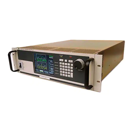
KEPCO BOP-MG Operator's Manual (194 pages)
1KW HIGH POWER BIPOLAR POWER SUPPLY
Brand:
KEPCO
| Category:
Power Supply
| Size: 4.43 MB
Table of Contents
Table of Contents
11
Power Supply
1
Declaration of Conformity
3
Safety Instructions
5
Safety Messages
6
Warnings and Cautions
7
List of Figures
18
Section 1 - Introduction
21
Scope of Manual
21
General Description
21
Specifications
21
Input Characteristics
22
Miscellaneous Features
29
Physical Characteristics
31
W BOP Power Supply, Outline Drawing
32
Rear View
33
Local Control
34
Remote Control
34
Features
34
Digital Calibration
34
Voltage/Current Protection
34
Waveforms
34
Saving and Recalling Settings
35
External Reference (Analog Control)
35
External Limits
35
User-Defined Voltage/Current Maximum Values (Software Limits)
35
Parallel and Series Configurations
35
Energy Recuperation
36
Equipment Supplied
36
Accessories
36
Safety
36
BOP Output Characteristics
37
Accessories
38
Section 2 - Installation
39
Unpacking and Inspection
39
Terminations and Controls
39
Rear Panel Connector Functions
40
Trigger Port Pin Assignments
41
RS232C PORT Input/Output Pin Assignments
42
Parallel/Serial Protect in Port Pin Assignments
43
Preliminary Operational Check
44
IEEE 488 Port Input/Output Pin Assignments
45
Installation
46
Rack Mounting
46
Slide Installation
46
Wiring Instructions
46
Safety Grounding
46
Source Power Connections
46
D-C Output Grounding
46
Grounding Network Configuration
47
Power Supply/Load Interface
47
Load Connection - General
48
Load Connection Using Local Sensing
49
Load Connection Using Remote Sensing
49
Cooling
49
Setting up the Unit
49
Consider the Load Type
49
Setup for Local Operation
49
Load Connections, Local Sensing
50
Load Connections, Remote Sensing
50
Setup for Remote Operation Via GPIB
51
Setup for Remote Operation Via RS 232C
51
Multiple Unit Configurations
51
Multiple Unit Source Power
52
Multiple Unit Protection
52
Parallel Configuration, Local Sensing, Typical
53
Parallel Configuration, Remote Sensing, Typical
54
Series Configuration, Local Sensing, Typical
55
Series Configuration, Remote Sensing, Typical
56
Configuring Parallel, Series, 2 X 2 or 3 X 2 Combinations
57
Multiple Units Menu Functions
58
Master Power up Screen
59
Power on Default Screen for Master Unit
60
Operating Instructions for Multiple Unit Combinations
61
Power on Default Screen for Slave Unit
61
Restoring a Unit to Standalone Operation
62
Changing Multiple Unit Configurations
62
X 2 (3 Series X 2 Parallel) Configuration, Local Sensing, Typical
63
Section 3 - Operation
65
General
65
Power Supply Basics
65
Keypad Description
65
Front Panel Keypad
66
LCD and Power-Up Screen Description
67
Power-Up Screen Showing Graphic Meters
68
Turning the Power Supply on
69
How to Access the Menus
70
Overall Menu Structure
70
How to Modify a Parameter
71
Password Setup
71
How to Access a Password Protected Menu
72
Operator Convenience Functions (Display Menu)
73
Adjusting LCD Brightness, Contrast and Background
73
Password Protection Menu, Factory Defaults
73
Displaying Programmed Settings in Remote Mode
74
Enabling/Disabling Audible Beeps
75
Displaying Meters or Graph (Time Line)
75
Waveform Stop
75
Local Mode Operation
75
Setting Local Mode
75
Keypad Lockout
75
Local Password Protection at Power-Up
76
Setting Voltage or Current Mode
76
Programming Voltage or Current and Associated Protect Limits
76
Voltage and Current Parameter Definitions
77
Selecting Bipolar/Independent Protection Limits
78
General Setup Menu
79
Max/Min Settings Menu
79
Understanding Voltage and Current Protect Limits
80
Hidden Voltage and Current Protect Limits
80
Changing Maximum or Minimum Software-Controlled Limits
80
Changing Maximum Accepted Voltage or Current (Main Channel Software Limits)
81
Changing Maximum/Minimum Protection Software-Controlled Limits
82
External Limits
83
Enabling/Disabling DC Output Power
83
Determining How the Unit Responds When Output Is off (Load Type)
84
Changing the Default Power up Settings
85
Examples Showing How Power-Up Settings Function
86
Storing/Recalling Power Supply Output Settings
87
Understanding Abbreviations Used for Saved Settings
87
Viewing Saved Settings
88
Saving Settings and Erasing or Modifying Previously Saved Settings
88
Copying Previously Saved Settings to a New Location
89
Saved Setups Menu
89
Applying Saved Settings to the Output (Recall)
90
Waveform Generation
90
Protecting the Load When Accessing Waveforms
90
Waveform Overview
90
Understanding How Waveforms Are Generated
91
Waveform Specifications
92
Viewing Stored Waveforms
93
Executing a Waveform
93
Waveform Settings Menu
93
Modifying Previously Stored Waveforms
94
Creating a New Waveform
94
Waveform Segment Details Menu
95
Using Segments to Build a Waveform
96
Sample Waveform
97
Copying a Waveform
98
Reset
99
Operator Testing
99
Error Message Explanations
100
Analog Remote Mode Programming
101
Remote Output off
101
Remote Shutdown
101
Remote Standby
102
Voltage/Current Mode Control
103
Controlling the Output Using the BOP as a Power Amplifier
103
Fixed Gain Using External Reference Control
103
Remote Standby, Standalone or Multiple Units
103
Analog Remote Setup Menu
104
Variable Gain Using External Reference Level
105
External Protection Limits
106
Using both Local/Digital and External Protection Limits
106
Monitoring Output Current Using an Analog Signal
107
Digital Remote Mode Programming
107
Operating Features Available Only by Remote Commands
107
Expanded Waveforms and Programs
107
Programming Techniques to Optimize Performance
107
Programming Voltage/Current Limit and Current/Voltage Limit
107
Making Sure the Previous Command Is Complete
108
Remote Mode Setup
109
GPIB Port Setup
110
Changing the GPIB Address
110
Configure Device Clear (DCL) Control
110
Determining Whether *RST Command Sets the Output off or on
111
RS 232 Serial Port Setup
111
Select Baud Rate
111
Configure XON/XOFF Protocol
111
Configure Prompt Mode
112
Establish Communication Language
112
BIT 4882 Compatibility
112
BIT 4886 Compatibility
112
LIST Command Differences in BIT 4886
112
Status Reporting Differences in BIT 4886
113
Trigger Operation Differences in BIT 4886
113
IEEE 488 (GPIB) Bus Protocol
113
BOP VISA Instrument Driver
114
RS232-C Operation
115
Serial Interface
115
RS 232 Implementation
115
XON XOFF Method
117
Echo Mode
117
Prompt Method
117
Using SCPI Commands for RS 232 Communication
117
Isolating RS 232 Communication Problems
118
SCPI Programming
118
SCPI Messages
118
Common Commands/Queries
119
SCPI Subsystem Command/Query Structure
119
Abort Subsystem
119
Display Subsystem
119
Initiate Subsystem
119
LIST Subsystem
119
Measure Subsystem
122
Output Subsystem
122
Memory Subsystem
122
Status Subsystem
122
Trigger Subsystem
123
Source:]Voltage and [Source:]Current Subsystems
123
Calibrate Subsystem
123
System Subsystem
123
Forgotten Passwords
123
Program Message Structure
124
Keyword
124
Message Structure
124
Keyword Separator
125
Query Indicator
125
Data
125
Data Separator
125
Message Unit Separator
126
Root Specifier
126
Message Terminator
126
Understanding the Command Structure
126
Program Message Syntax Summary
127
Status Reporting
127
Status Reporting Structure
128
Typical Example of BOP Power Supply Program Using SCPI Commands
129
Operational Status Register
130
Questionable Status Register
131
SCPI Program Examples
131
Section 4 - Calibration
133
General
133
Test Equipment Requirements
134
Suggested Sense Resistors
135
Calibration Using Remote SCPI Commands Via GPIB or RS 232 Interface
136
Calibration Procedure Using SCPI Commands
137
Calibration Setup for Current Mode
140
Calibration Using Front Panel Keypad in Local Mode
142
Understanding the Calibration Process
142
Main Calibration Screen
143
Calibration Procedure Using Local Mode
144
Calibration Storage
147
Calibration Storage
148
Appendix A - Scpi Common Command/Query Definitions
149
CLS - Clear Status Command
149
ESE - Standard Event Status Enable Command
149
A.2 *CLS — Clear Status Command
149
ESE? - Standard Event Status Enable Query
150
ESR? - Event Status Register Query
150
IDN? - Identification Query
150
OPC - Operation Complete Command
150
A.4 *ESE? — Standard Event Status Enable Query
150
OPC? - Operation Complete Query
151
A.8 *OPC? — Operation Complete Query
151
OPT? - Options Query
152
RCL - Recall Command
152
RST - Reset Command
152
SAV - Save Command
152
A.9 *OPT? — Options Query
152
SRE - Service Request Enable Command
153
SRE? - Service Request Enable Query
153
STB? - Status Byte Register Query
153
TRG - Trigger Command
153
A.13 *SRE — Service Request Enable Command
153
TST? - Self Test Query
154
WAI - Wait-To-Continue Command
154
A.17 *TST? — Self Test Query
154
Appendix B - Scpi Command/Query Definitions
155
Introduction
155
Abor
155
B.1 Introduction
155
CAL Commands and Queries
156
B.2 Numerical Values
156
Initiate[:Immediate] COMMAND
157
B.5 INIT Iate [:IMM Ediate ] Command
157
Init:cont
158
Initiate:continuous COMMAND
158
Initiate:continuous QUERY
158
Measure[:Scalar]:Current[:DC]? QUERY
158
Measure[:Scalar]:Mode[:DC] COMMAND
158
Measure[:Scalar]:Voltage[:DC]? QUERY
158
Measure[:Scalar]:Transient[:DC]? QUERY
158
B.6 INIT Iate :CONT Inuous Command
158
Mem:upd
159
Memory:update COMMAND
159
B.12 MEM Ory :UPD Ate Command
159
Using List Commands to Measure Sample at End of Pulse
159
Using List Commands to Measure Sample at Start of Pulse
160
Ut [:STAT E ] Command
160
Ut :CONT Rol Command
161
El ]:LIM It [:BOTH] Command
162
El ]:LIM It :NEG Command
163
Ce :]CURR Ent :Mode? Query
164
El ]:PROT Ect :Neg Ative ? Query
165
Ce :]FUNC Tion :MODE? Query
166
B-5 Using LIST Commands and Queries
167
T Command
168
B-2 List Data Table
169
APPL y :SWE Ep Command
170
Command
171
VOLT Age Command
172
Bop-1K
173
B-6 Using List:wait Commands to Control Generation of a Waveform Measured by Multiple External Devices Using a Single External Pulse
174
Multiple External Devices Using a Single External Pulse
174
Using List:wait Commands to Allow an External Device Time to Function While Imposing a Maximum Wait Time
175
Age :APPL y Command
176
B.84 [SOUR Ce :]List:wait:ledge Command
177
B-8 Using List:wait Commands to Control Generation of a Waveform Measured by Multiple External Devices Using the Low-Going Leading Edge of an External Pulse
178
Multiple External Devices Using the Low-Going Leading Edge of an External Pulse
178
LEV el ]:LIM It [:BOTH]? Query
179
LEV el ]:LIM It :Pos Itive ? Query
180
B-9 Using PROT:LIM:POS and PROT:LIM:POS Commands to Set Asymmetrical Limits
181
LEV el ]:PROT Ect :POS Itive Command
182
Query
183
B-4 Questionable Event Register, Questionable Condition Register and Questionable Condition Enable Register Bits
184
Using Status Commands and Queries
185
B.128 System:communication:serial:pace Command
186
B.130 System:communication:serial:prompt Command
187
Setting the Unit to Remote Mode Via Serial (RS 232) Port
188
STAT E ? Query
188
Using System Commands and Queries
189
B-5 Error Messages
190
Bop-1K
191
Advertisement
Advertisement
Related Products
KEPCO BOP-MG 1KW
KEPCO BOP-MG/ME 1KW
KEPCO BOP-ME 1KW
KEPCO BOP 200W
KEPCO BOP 400W
KEPCO BOP 50-2
KEPCO BOP 100-20MG
KEPCO BOP 25-40ME
KEPCO BOP 6-125G
KEPCO BOP 20-50G
KEPCO Categories
Power Supply
Adapter
Protection Device
Racks & Stands
Cables and connectors
More KEPCO Manuals
Login
Sign In
OR
Sign in with Facebook
Sign in with Google
Upload manual
Upload from disk
Upload from URL