Sign In
Upload
Manuals
Brands
Kayden Manuals
Switch
CLASSIC 830
Kayden CLASSIC 830 Manuals
Manuals and User Guides for Kayden CLASSIC 830. We have
3
Kayden CLASSIC 830 manuals available for free PDF download: Product Manual
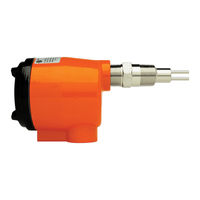
Kayden CLASSIC 830 Product Manual (104 pages)
Thermal Flow, Level, Interface & Temperature Switches & Transmitters
Brand:
Kayden
| Category:
Switch
| Size: 18.45 MB
Table of Contents
Table of Contents
3
CLASSIC 800 Specifications
7
Overview of CLASSIC Setup
9
Introduction
9
Models Described in this Manual
11
Classic
12
Typical Applications
12
The Kayden Classic 800 - Digital Electronics Features
13
Principle of Operation
14
Figure 2 - CLASSIC 800 Probe & Outputs
14
Thermal Signal
15
Figure 3 - Thermal Signal Vs Velocity in Glycol
15
Figure 4 - Thermal Signal Dry Vs Submerged
15
4-20 Ma ANALOG OUTPUT
16
Figure 5 - Thermal Signal Submerged Vs Dry
16
Figure 6 - Thermal Signal in Alternate Fluids
16
Installation Guidelines
17
General
17
Figure 7 - Pump Flow Detection
17
Application Principles - Flow, Level, Interface & Temperature
18
Application Considerations
18
Application Considerations - Flow
18
Application Considerations - Level
19
Application Considerations - Interface
19
Application Considerations - Temperature
20
Electronics Location Considerations
20
Guidelines for Pipe Mounting
21
Horizontal Pipe - Side Mount (Ideal)
21
Horizontal Pipe - Top Mount
21
Horizontal Pipe - Bottom Mount
21
Figure 8 - Insertion 'U' Length (Flanged)
21
Figure 9 - Insertion 'U' Length
21
Figure 10A - Horizontal Pipe, Side Mounting
21
Figure 10B - Horizontal Pipe, Top / Bottom Mounting
21
Vertical Pipe - Side Mount (Acceptable)
22
Vertical Pipe - Side Mount - Downward Flow
22
Vertical Pipe - Top & Bottom Mount (Less Desirable)
22
Figure 11 - Vertical Pipe, Flow up & down
22
Figure 12 - Horizontal Pipe, Sensor Positioning
22
Installing the Sensor
23
Figure 13 - Sensor Orientation for Horizontal Flow & Level
23
Electrical
24
Figure 14 - Disconnecting Sensor Connector from the Electronics Module
25
Local Enclosure Wiring Diagrams
27
Wiring Connection Diagram - Local
27
Figure 15 - CLASSIC 800 Electronics Module Terminal Wiring Diagram
27
Remote Enclosure Wiring Diagrams & Applications
28
Figure 16 - CSA Remotely Mounted Electronics
28
Figure 17 - FM Remotely Mounted Electronics
28
Interconnecting Cables for Remote Electronics
29
General Purpose (Non-Hazardous) Cable & Connector Assembly
29
Flameproof Cable & Connector Assembly
29
Wiring Connection Diagram - Remote
30
Figure 18 - A06-XP Remote Cable and Connector Spec Drawing
30
Figure 19 - CLASSIC 800 Wiring Diagram (Remote)
31
Optional Wiring Methods for 4-20 Ma Current Loop
32
Figure 20 - DC Powered CLASSIC, 4-Wire External Loop Power (Current Sinking)
32
Figure 21 - DC Powered CLASSIC, 3-Wire Internal Loop Power (Current Sourcing)
32
Figure 22 - AC Powered CLASSIC, 4-Wire External Loop Power (Current Sinking)
33
Testing the Installation
34
Quick Setup Guide
35
Mechanical Installation
35
Sensor Orientation
35
Setup & Configuration Flow Chart
36
Display Panel Indicators
37
Display Panel Button Functions
37
Power AC/DC
38
Relay Outputs
38
Heater Power
38
Setup & Operation
39
Display Panel Indicators
39
Display Panel Button Functions
39
General Information
40
CONTROL SETTINGS and SETUP PROCEDURES
40
View or Adjust Relay 1 & 2 Energized Mode
41
Figure 23 - Relay Energized Mode
41
Failsafe Relay Configurations
42
View or Adjust the 4-20 Ma Fault Mode Configuration
43
Figure 24 - 4-20 Ma Fault Mode Configuration
43
View or Adjust Set Points 1 & 2
44
Figure 25 - Set Point 1 & 2 Configuration
44
View or Adjust the Start-Up Bypass Timer
45
Figure 26 - Start-Up Bypass Timer
45
View or Adjust the Heater Power
46
Figure 27 - Setting the Heater Power
46
View or Adjust the Node Address & View the Software Revision
47
Figure 28 - Software Revision & Node (Unit) Number
47
View or Adjust the 4-20 Ma Output Configuration (Forward or Reverse Acting)
48
Figure 29 - 4-20 Ma & 20-4 Ma Output Mode
48
View the Bar Graph Lower Range Value (0%) and Upper Range Value (100%)
49
Figure 30 - Maximum Range of Lower Range Value (LRV) & Upper Range Value (URV)
49
Figure 31 - Scaled Bar Graph View Vs. Unscaled Bar Graph View
49
Adjust the Bar Graph Lower Range Value (0%) and Upper Range Value (100%)
50
Figure 32 - Setting the Scaled Thermal Signal LRV
50
Figure 33 - Setting the Scaled Thermal Signal URV
50
Additional Setup Features Using Kayden RCM Software Via Modbus RTU
51
Kayden Setting & Configuration Log Sheet
52
Modbus Rtu Interface
53
Modbus History
53
Modbus Implementation
53
Node Address
53
Function Codes
53
Table 1 - Modbus Address Binary Table
53
Table 2 - CLASSIC Modbus Function Codes
53
Coils
54
Holding Registers
54
Table 3 - Coils
54
Table 4 - Low Holding Registers (Configuration and Status)
54
Table 5 - High Holding Registers (Run-Time Variables)
56
Maintenance
58
Cover
58
Process and Conduit Connections
58
Figure 34 - Kayden CLASSIC Exploded View
58
Sensing Elements
59
Electronics Module
59
Adjustment & Calibration
59
Preventative Maintenance W/ RCMS
59
Troubleshooting
60
Figure 35 - Display Panel Indicators
60
LED Fault Indicator
61
LED Fault Codes
61
Figure 36 - Fault Cycle Display Example
61
Fault Check List
67
Restore Operation after a Fault
67
Options for Clearing a Fault
67
How to Perform a Factory Reset
68
How to Check the Sensor
68
Figure 37 - Checking Sensor Resistances
68
Return of Material
69
Hazardous Materials
69
Service, Technical Support & Contact Information
69
Glossary
70
Appendix A - Outline Dimensional Drawing
74
Threaded
74
Flanged
74
CLASSIC ® 814 Retractable Packing Gland Flanged - to 50 Psi
75
CLASSIC ® 814 Retractable Packing Gland Threaded - to 125 Psi
75
CLASSIC ® 816 Retractable Packing Gland Threaded - 1" MNPT - to 50 Psi
76
CLASSIC ® 816 Retractable Packing Gland Threaded - 1" MNPT - C/W Chain - to 125 Psi
76
CLASSIC ® 816 Retractable Packing Gland Threaded - 1" MNPT - to 500 Psi
76
Inline Threaded (Horizontal)
77
Inline Threaded (Vertical)
77
Inline Flanged (Horizontal)
77
CLASSIC ® 832 Inline Flanged (Vertical)
78
Remote Electronics Enclosure - Flameproof (CSA)
78
Remote Electronics Enclosure - Flameproof (FM)
79
Appendix B - Model Number Legends
80
CLASSIC ® 810 Threaded
81
CLASSIC ® 812 Flanged
82
CLASSIC ® 814 Flanged Retractable Packing Gland
83
CLASSIC ® 816 Threaded Retractable Packing Gland
84
Inline Threaded
85
Inline Flanged
86
Appendix C - Kayden.com Web Site
87
Appendix E - Rcm Software Installation & Use
88
Contact Us, Distributors and Ordering Information
103
Advertisement
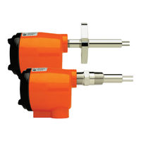
Kayden CLASSIC 830 Product Manual (72 pages)
CLASSIC 800 Series Thermal Flow, Level, Interface & Temperature Switches & Transmitters
Brand:
Kayden
| Category:
Switch
| Size: 12.75 MB
Table of Contents
Table of Contents
3
Specifications
6
Agency Approvals
7
Introduction
8
CLASSIC ™ 800 Specifications
8
Overview of Switch Transmitter Setup
8
Models Described in this Manual
9
Classic
10
Typical Applications
10
CLASSIC ™ 800 Electronics
10
The Kayden Classic 800 - Digital Electronics Features
11
Principle of Operation
12
II. Principle of Operation
12
Thermal Signal
13
Figure 2 - How Thermal Conductivity Is Displayed
13
4-20 Ma ANALOG OUTPUT
14
Figure 3 - 4-20 Ma Wiring
14
Installation Guidelines
15
General
15
Figure 3A - Pump Flow Detection
15
Application Considerations
16
Application Considerations - Flow
16
Application Principles - Flow, Level, Interface & Temperature
16
Application Considerations - Level
17
Application Considerations - Interface
17
Guidelines for Pipe Mounting
18
Horizontal Pipe - Side Mount (Ideal)
18
Horizontal Pipe - Top Mount
18
Horizontal Pipe - Bottom Mount
18
Figure 4 - Threadolet
18
Figure 6A - Horizontal Pipe, Side Mounting
18
Figure 5 - Insertion 'U' Length
18
Figure 6B - Horizontal Pipe, Top / Bottom Mounting
18
Vertical Pipe - Side Mount (Acceptable)
19
Vertical Pipe - Side Mount - Downward Flow
19
Vertical Pipe - Top & Bottom Mount (Less Desirable)
19
Figure 8 - Vertical Pipe, Flow up & down
19
Figure 7 - Horizontal Pipe, Sensor Positioning
19
Installing the Sensor
20
Figure 9 - Sensor Orientation for Horizontal Flow & Level
20
Electrical
21
Figure 10 - Disconnecting Sensor Connector from the Electronics Module
22
Figure 11 - CLASSIC 800 Mounting Base Plate / Wiring Terminal
22
Figure 12 - CLASSIC 800 Wiring Connection Diagram
23
Wiring Connection Diagram
23
Testing the Installation
24
Table of Figures
25
Setup & Operation
25
Display Panel Indicators
25
Display Panel Button Functions
25
Figure 1 - CLASSIC 800 Display Panel
25
Figure 14 - Control Functions RUN/SET Mode
25
General Information
26
CONTROL SETTINGS and SETUP PROCEDURES
26
View or Adjust Relay 1 & 2 Energized Mode
27
Figure 15 - Relay Energized Mode
27
Failsafe Relay Configurations
28
View or Adjust the 4-20 Ma Fault Mode Configuration
29
Figure 16 - 4-20 Ma Fault Mode Configuration
29
View or Adjust Set Points 1 & 2
30
Figure 17 - Set Point 1 & 2 Configuration
30
View or Adjust the Start-Up Bypass Timer
31
Figure 18 - Start-Up Bypass Timer
31
View or Adjust the Heater Power
32
Figure 19 - Setting the Heater Power
32
View or Adjust the Node Address & View the Software Revision
33
Figure 20 - Software Revision & Node (Unit) Number
33
View or Adjust the 4-20 Ma Output Configuration (Forward or Reverse)
34
Figure 21 - 4-20 Ma & 20-4 Ma Output Mode
34
View or Adjust the 0% & 100% Thermal Signal Scaled Bar Graph View
35
Figure 22 - Scaled Bar Graph View Vs. Baseline Bar Graph View
35
View or Adjust the 0% & 100% Thermal Signal Leds
36
Figure 23 - Setting the 0% & 100% Thermal Signal
36
Kayden RCM Software
37
Communication Cable
38
Converters / Adapters - USB to RS-232 & RS-232 to RS-485
38
RS-485 Remote Communications
38
Quick Setup Guide
39
Mechanical Installation
39
Sensor Orientation
39
Setup & Configuration Flow Chart
39
Display Panel Button Functions
39
Power AC/DC
39
Relay Outputs
39
Display Panel Indicators
41
Heater Power
42
Maintenance
43
Cover
43
Process and Conduit Connections
43
Sensing Elements
43
Preventative Maintenance Requirements
43
Electronics Module
44
Adjustment & Calibration
45
Binary Table
46
LED Fault Indicator
47
Troubleshooting
47
How to Reset the CLASSIC Factory Settings
48
Resistance Values for Sensor Wiring
48
Figure 24 - Factory Reset
48
Figure 25 - Display Panel Indicators
49
Return of Material
50
Hazardous Materials
50
Service, Technical Support & Contact Information
50
Glossary
51
Appendix A - Outline Dimensional Drawing
52
CLASSIC ™ 810 Threaded
52
812 Flanged
52
CLASSIC ™ 828 Sanitary Flanged
52
CLASSIC ™ 830 Inline Threaded (Horizontal)
53
CLASSIC ™ 830 Inline Threaded (Vertical)
53
CLASSIC ™ 832 Inline Flanged (Horizontal)
54
CLASSIC ™ 832 Inline Flanged (Vertical)
54
CLASSIC ™ 816 Retractable Packing Gland Threaded - 1" MNPT - to 50 Psi
54
CLASSIC ™ 816 Retractable Packing Gland Threaded - 1" MNPT - C/W Chain - to 125 Psi
55
CLASSIC ™ 816 Retractable Packing Gland Threaded - 1" MNPT - to 500 Psi
55
CLASSIC ™ 814 Retractable Packing Gland Flanged - to 50 Psi
55
CLASSIC ™ 814 Retractable Packing Gland Threaded - to 125 Psi
56
Remote Electronics Enclosure - Flameproof (CSA)
56
Remote Electronics Enclosure - Flameproof (FM)
57
Appendix B - Model Number Legends
58
Order Legends
59
CLASSIC ™ 810 Threaded
59
CLASSIC ™ 812 Flanged
60
CLASSIC ™ 830 Inline Threaded
61
CLASSIC ™ 832 Inline Flanged
62
CLASSIC ™ 816 Threaded Retractable Packing Gland
63
CLASSIC ™ 814 Flanged Retractable Packing Gland
64
CLASSIC ™ 828 Sanitary Flanged
65
Appendix C - Telematic.com Web Site
66
Contact Us & Ordering Information
71
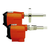
Kayden CLASSIC 830 Product Manual (77 pages)
Thermal Flow, Level, Interface & Temperature Switches & Transmitters
Brand:
Kayden
| Category:
Switch
| Size: 5.58 MB
Advertisement
Advertisement
Related Products
Kayden CLASSIC 810
Kayden CLASSIC 812
Kayden CLASSIC 828
Kayden CLASSIC 814
Kayden CLASSIC 832
Kayden CLASSIC 816
Kayden CLASSIC 800 Series
Kayden CLASSIC 821
Kayden CLASSIC Series
Kayden Categories
Switch
Inverter
More Kayden Manuals
Login
Sign In
OR
Sign in with Facebook
Sign in with Google
Upload manual
Upload from disk
Upload from URL