Sign In
Upload
Manuals
Brands
KAESER Manuals
Air Compressor
M27
KAESER M27 Manuals
Manuals and User Guides for KAESER M27. We have
1
KAESER M27 manual available for free PDF download: Operator's Manual
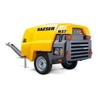
KAESER M27 Operator's Manual (294 pages)
Screw Compressor
Brand:
KAESER
| Category:
Air Compressor
| Size: 9.29 MB
Table of Contents
Table of Contents
2
1 Regarding this Document Using this Document
11
Further Documents
11
Copyright
11
Symbols and Labels
11
Warnings
11
Tab. 1 Danger Levels and Their Definitions (Personal Injury)
11
Potential Damage Warnings
12
Other Alerts and Their Symbols
12
Tab. 2 Danger Levels and Their Definition (Damage to Property)
12
2 Technical Data Nameplate
14
Options
14
Tab. 3 Nameplate
14
Compressed Air Treatment Devices
15
Tool Lubricator
15
Compressed Air Distributor
15
Tab. 4 Options Label
15
Tab. 5 Compressed Air Treatment Options
15
Tab. 6 Tool Lubricator Option
15
Tab. 7 Compressed Air Distributor Option
15
Non-Return Function
16
Low Temperature Equipment
16
Equipment for Fire Hazard Areas
16
Fuel De-Watering Filter
16
Battery Isolating Switch
16
Tab. 8 Non-Return Option
16
Tab. 9 Low Temperature Equipment Options
16
Tab. 10 Optional Equipment for Fire Hazard Areas
16
Tab. 11 Option Ne: Fuel De-Watering Filter
16
Tab. 12 Battery Isolating Switch Option
16
Generator
17
Chassis
17
Lighting
17
Tab. 13 Generator Option
17
Tab. 14 Chassis Options
17
Sealed Floor Pan
18
Hose Reels
18
Anti-Theft Device
18
Machine (Without Options)
18
Sound Pressure Level
18
Tightening Torques for Screws
18
Tab. 15 Lighting Options
18
Tab. 16 Sealed Floor Pan Option
18
Tab. 17 Hose Reel Option
18
Tab. 18 Anti-Theft Device Option
18
Ambient Conditions
19
Additional Specifications
19
Chassis
19
Weight of Machines Approved for Towing on Public Roads
19
Tab. 21 Torque Cover Fixing Screws Oil Separator Tank
19
Tab. 22 Torques for Lifting Eye Screws
19
Tab. 23 Ambient Conditions
19
Tires
20
Fig. 1 Example for Tire Information on the Side Wall
20
Tab. 24 Weight of the Machine
20
Wheel Nut/Bolt Tightening Torque
21
Towbar Tightening Torque
21
Compressor
21
Air Quality at the Compressed Air Outlets
21
Compressed Air Outlet
21
Working Pressure and FAD
21
Tab. 25 Technical Data - Tires and Wheel Bolts
21
Tab. 26 Wheel Nut/Bolt Tightening Torque
21
Tab. 27 Towbar Tightening Torque
21
Tab. 28 Working Pressure and FAD
21
Safety Relief Valve
22
Temperature
22
Cooling Oil Recommendation
22
Tab. 30 Interrelation between Compressed Air Treatment and Compressed Air Quality
22
Tab. 31 Relief Valve Activating Pressure
22
Tab. 32 Machine Temperatures
22
Cooling Oil Charge
23
Engine
23
Engine Data
23
Tab. 33 Cooling Oil Recommendation
23
Tab. 34 Cooling Oil Charge
23
Oil Recommendation
24
Fuel Recommendation
24
Engine Coolant Recommendation
24
Tab. 35 Engine Data
24
Tab. 36 Engine Oil Recommendation
24
Fluid Volumes
25
Batteries
25
Options
25
Low Temperature Equipment
25
Tool Lubricator
25
Tab. 37 Fluid Volumes
25
Tab. 38 Batteries
25
Tab. 39 Road Breaker Lubricant Recommendation
25
Tab. 40 Ambient Conditions, Low Temperature Equipment
25
Generator
26
Tab. 41 Coolant Pre-Heater
26
Tab. 42 Recommended Anti-Freeze
26
Tab. 43 Generator Data, 400V
27
Tab. 44 Compressed Air Delivery in Generator Mode
27
Tab. 45 Connection Sockets
27
Tab. 46 Circuit Breaker
27
Tab. 47 Maximum 3-Phase Power Supply
28
Tab. 48 Maximum Single Phase Power Supply
28
Tab. 49 Generator Data 115V
28
Tab. 50 Compressed Air Delivery in Generator Mode
29
Tab. 51 Connection Sockets
29
Tab. 52 Circuit Breaker
29
Air Hose with Hose Reel
30
Tab. 53 Maximum Single-Phase Power Supply Loading
30
Tab. 54 Generator Operating Limits
30
Tab. 55 Output Power Reduction
30
Tab. 56 Additional Discharge Valve for the Air Hose
30
3 Safety and Responsibility Basic Instructions
31
Specified Use
31
Incorrect Use
31
User's Responsibilities
31
Observe Statutory and Universally Accepted Regulations
31
Determining Personnel
32
Adherence to Inspection Schedules and Accident Prevention Regulations
32
Dangers
32
Safely Dealing with Sources of Danger
33
Safe Machine Operation
35
Organizational Measures
39
Danger Areas
39
Safety Devices
39
Safety Signs
39
Tab. 57 Danger Areas
39
Fig. 2 Locations of Safety Signs
40
Generator Operation
42
Comply with the Protective Measures against Dangerous Electric Current
42
Tab. 58 Safety Signs
42
Instructions for Safe Generator Operation
43
Connecting Extension Cables
43
Do Not Exceed the Maximum Supply System Load
43
Perform Regular Generator Inspections
43
Emergency Situations
44
Correct Fire Fighting
44
Injury from Handling Operating Fluids/Materials
44
Warranty
45
Environmental Protection
45
4 Design and Function Bodywork
47
Fig. 3 Bodywork
47
Component Identification
48
Fig. 4 Side View (Canopy Removed)
48
Machine Function
49
Fig. 5 General Design
49
Operating Modes and Control Modes
50
Operating Modes
50
MODULATING Control
50
Safety Devices
51
Monitoring Functions with Shutdown
51
Further Safety Devices
51
Options
51
Compressed Air Treatment Options
51
Fig. 6 Compressed Air Treatment Options
52
Fig. 7 Tool Lubricator
52
Generator Option
53
Tab. 59 Generator Mode Selector Switch
54
Tab. 60 Generator Operating Modes
54
Low Temperature Equipment Options
55
Fig. 8 Instrument Panel, Generator Control Box 400 V/3~/N/PE, 50 Hz
55
Fig. 9 Instrument Panel, Generator Control Box 115 V/1~/N/PE, 50 Hz, 32 a
55
Fig. 10 Coolant Pre-Heating
56
Options for Operating in Fire Hazard Areas
57
Fig. 11 Frost Protector
57
Fuel De-Watering Filter Option
58
Sealed Floor Pan Option
58
Battery Isolating Switch
58
Hose Reel Option
59
Optional Anti-Theft Device
59
Fig. 12 Battery Isolating Switch
59
Fig. 13 Container for Safety Chain
59
Transportation Options
60
Tab. 61 Chassis - Overview
61
5 Installation and Operating Conditions
62
Ensuring Safety
62
Installation Conditions
62
Fig. 14 Minimum Distance from Excavations/Slopes and Walls
63
6 Installation
65
Ensuring Safety
65
Reporting Transport Damage
65
Fitting the Towbar
65
Fitting the Height-Adjustable Towbar
66
Fig. 15 Fitting the Height-Adjustable Towbar
66
Fitting the Fixed Height Towbar
68
Fig. 16 Fitting the Fixed Height Towbar
68
Installing the Fixed Height Towbar (US Towbar)
69
Adjusting the Chassis
69
Fig. 17 Fixed Height Towbar
69
Tab. 62 Height-Adjustable Towbar
69
Adjusting the Towbar Height
70
Fig. 18 Towbar Height Adjustment Rb/Rm/Rr
70
Adjusting the Towbar Height
71
Fig. 19 Towbar Height Adjustment Rb/Rm/Rs
72
Replacing the Ball Coupling with a Towing Eye
73
Fig. 20 Replacing the Ball Coupling (Height-Adjustable Towing System)
74
Fig. 21 Replacing the Ball Coupling (Towing Device with Overrun Brake)
76
Fig. 22 Distance Elements, Towing Adapter
77
Tab. 63 Distance Elements
77
Fig. 23 Changing the Towing Eye
79
Fig. 24 Replacing the Towing Eye with a Ball Coupling
81
Fig. 25 Distance Elements
82
Fig. 26 Changing the Towing Eye (Towbar - US Version)
83
7 Initial Start-Up Ensuring Safety
85
Before Initial Start-Up (or Recommissioning)
85
Instructions to be Observed before Commissioning or Recommissioning
85
Special Measures for Recommissioning after Storage
86
Checking Installation and Operating Conditions
86
Tab. 64 Measures for Recommissioning the Compressor after a Long Period of Storage
86
Tab. 65 Installation Conditions Checklist
86
Low-Temperature Operation (Winter)
87
Starting Assistance
87
Fig. 27 Jumper Cable Connection Diagram
88
Starting up Low-Temperature Equipment
89
Fig. 28 Coolant Pre-Heating
89
Activating the Generator
90
Generator Control Box 400V with Insulation Monitoring
90
Fig. 29 Insulation Monitoring - 400V, 3-Phase Generator
90
Tab. 66 Low-Temperature Equipment Checklist
90
Generator Control Box 115V with Insulation Monitoring
91
Testing the Insulation Monitor
91
Fig. 30 Insulation Monitoring - 115V, Single-Phase Generator
91
Tab. 67 Test Instructions for a Generator with a Ground Short Detection Device
91
8 Operation
93
Ensuring Safety
93
Starting and Stopping
94
Fig. 31 Starting Instruments
94
Running the Machine
95
Starting the Machine
95
Allow the Machine to Run up to Operating Temperature
95
Fig. 32 Label Referring to the Warm-Up Period When Ambient Temperatures Are below 14 °F
95
The Machine Is Running under Load
96
Shutting down the Machine
96
Operating the Tool Lubricator
96
Fig. 33 Setting the Tool Lubricator
97
Using the Low-Temperature Equipment
98
Coolant Pre-Heating
98
Operating the Machine with Frost Protector
98
Fig. 34 Frost Protector on and off
98
Generator Operation
99
Before You Operate the Generator
99
Disconnect Electric Consumers
100
Switching on the Generator
100
Fig. 35 Generator Cut-In Pictogram
100
Switching off the Generator
101
Operating the Battery Isolating Switch
101
Fig. 36 Battery Isolating Switch
101
Using the Hose Reel
102
Operating the Machine with an Extension Air Hose
102
Fig. 37 Hose Reel
102
Operating the Machine Without an Extension Air Hose
103
Securing the Hose Reel for Transport
103
Cleaning the Machine after Operation
103
9 Fault Recognition and Rectification
105
Basic Instructions
105
Engine Faults and Alarms
105
Engine Refuses to Start or Comes to a Stop
105
Engine Does Not Reach Full Speed
106
Indicator Lamp Remains on
106
Tab. 68 Alarm: Engine Refuses to Start or Comes to a Stop
106
Tab. 69 Alarm: Engine Does Not Reach Full Speed
106
Compressor Faults and Alarms
107
Working Pressure too High
107
Working Pressure too Low
107
Tab. 70 Indicator Lamp Remains on
107
Tab. 71 Alarm: Working Pressure too High
107
Safety Relief Valve Blowing off
108
Machine Overheating
108
Tab. 72 Alarm: Working Pressure too Low
108
Tab. 73 Alarm: Safety Relief Valve Blowing off
108
Too Much Oil Residue in the Compressed Air
109
Oil Flows from the Compressor Air Filter after Shutdown
109
Tab. 74 Alarm: Machine Overheating
109
Tab. 75 Fault: too Much Oil Residue in the Compressed Air
109
Tab. 76 Fault: Oil Flows from the Compressor Air Filter after Shutdown
109
High Moisture Content in the Compressed Air
110
Generator Faults and Alarms
110
No Voltage or too Low a Voltage from the Generator
110
Generator Voltage too High
110
Tab. 77 Fault: High Moisture Content in the Compressed Air
110
Tab. 78 Fault: no Voltage or too Low a Voltage from the Generator
110
Tab. 79 Fault: Generator Voltage too High
111
10 Maintenance
112
Ensuring Safety
112
Tab. 80 Advise Others that the Machine Is Being Serviced
112
Maintenance Schedules
113
Logging Maintenance Work
113
Maintenance Tasks after Commissioning
113
Regular Maintenance Tasks
114
Tab. 81 Maintenance Tasks after Commissioning
114
Tab. 82 Maintenance Intervals and Regular Maintenance Tasks
114
Tab. 83 Regular Machine Maintenance Tasks
117
Engine Maintenance
118
Tab. 84 Regular Maintenance Task Options
118
Water Cooler Maintenance
119
Fig. 38 Checking Coolant Level
120
Tab. 85 KAESER Coolant Mixture Table
121
Fig. 39 Draining the Coolant from the Radiator
122
Engine Air Filter Maintenance
123
Fig. 40 Maintenance Indicator
124
Fig. 41 Engine Air Filter Maintenance
124
Fig. 42 Cleaning the Filter Element
125
Fuel System Maintenance
126
Fig. 43 Bleeding the Fuel System
127
Fig. 44 Fuel Filter with Water Trap
129
Changing the Engine Oil
130
Fig. 45 Changing the Engine Oil
131
Fig. 46 Detail Oil Drain Valve
131
Tab. 86 Oil Drain Valve
131
Changing the Engine Oil Filter
133
Fig. 47 Changing the Engine Oil Filter
133
Drive Belt Maintenance
134
Fig. 48 Belt Tension Checking by Hand
135
Battery Maintenance
136
Fig. 49 Safety Signs - Warning Stickers on the Battery
136
Checking the Fastening of the Fuel Tank
139
Compressor Maintenance
139
Checking Cooling Oil Level
139
Filling or Topping off the Cooling Oil
140
Fig. 50 Checking Cooling Oil Level
140
Changing the Cooling Oil
141
Fig. 51 Draining the Compressor Cooling Oil
142
Replace the Compressor Oil Filter
143
Tab. 87 Oil Drain Valve
143
Fig. 52 Changing the Oil Filter
144
Oil Separator Tank Dirt Trap Maintenance
145
Fig. 53 Oil Separator Tank Dirt Trap Maintenance
145
Changing the Oil Separator Cartridge
146
Fig. 54 Changing the Oil Separator Cartridge
147
Compressor Air Filter Maintenance
149
Fig. 55 Maintenance Indicator
150
Fig. 56 Compressor Air Filter Maintenance
150
Checking Safety Relief Valves
151
Cleaning the Cooler
151
Cleaning the Compressor Cooler and Engine Radiator
152
Tab. 88 Connecting Elements
152
Cleaning the Compressed Air Aftercooler
153
Fig. 57 Cleaning the Compressed Air Aftercooler
153
Maintenance of Rubber Sealing Strips
154
Chassis Maintenance
154
Wheel Checks
154
Checking Wheel Bearings
155
Tab. 89 Maintenance According to Mileage
155
Tab. 90 Maintenance According to Time Interval
155
Fig. 58 Adjusting the Bearing Play
157
Fig. 59 Remove the Wheel Hub with Tapered Roller Bearing
158
Fig. 60 Install the Wheel Hub with Tapered Roller Bearing
159
Fig. 61 Securing the Collar of the Locknut
159
Towbar Maintenance
160
Tab. 91 Lubricating Points of the Towbar
161
Brake System Maintenance
162
Fig. 62 Ball Coupling (EU Version)
162
Fig. 63 Ball Coupling (US Version)
162
Fig. 64 Checking the Brake Lining Thickness
163
Fig. 65 Brake System Adjustment
164
Maintenance for Optional Items
165
Fig. 66 Brake Rod Adjustment
165
Tool Lubricator Maintenance
166
Fig. 67 Tool Lubricator Maintenance
166
Compressed Air Water Separator Maintenance
167
Fig. 68 Cleaning the Dirt Trap
167
Frost Protector Maintenance
168
Engine Air Intake Shut-Off Valve Maintenance
169
Fig. 69 Filling the Frost Protector
169
Fig. 70 Engine Air Intake Shut-Off Valve Maintenance
170
Draining Liquid Accumulation Within the Machine
171
Generator Drive Belt Maintenance
172
Fig. 71 Replacing the Generator Belt
172
Documenting Maintenance and Service Work
174
Tab. 92 Maintenance Log
174
11 Spares, Operating Materials, Service
175
Note the Nameplate
175
Ordering Consumable Parts and Operating Fluids/Materials
175
Tab. 93 Compressor Spare Parts
175
Tab. 94 Engine Spare Parts
175
Kaeser Air Service
176
Service Addresses
176
Replacement Parts for Service and Repair
176
12 Decommissioning, Storage and Transport
226
Commissioning
226
Temporary De-Commissioning
226
Tab. 95 "Temporarily Decommissioned" Information Notice
226
Long-Term Decommissioning and Storage
227
Tab. 96 "Long-Term Decommissioning and Storage" Checklist
227
Transport
228
Safety
228
Towing the Compressor on the Road
228
Tab. 97 "Long-Term Decommissioning and Storage" Information Notice
228
Fig. 72 Transport Position
229
Fig. 73 Ball Coupling (EU Version)
230
Fig. 74 Wear Alert, Ball Coupling (EU Version)
231
Fig. 75 Ball Coupling (US Version)
232
Tab. 98 Ball Coupling, Wear Indicator
232
Fig. 76 Release the Parking Brake with Gas Spring Assistance
233
Fig. 77 Automatic Jockey Wheel in Transport Position
233
Fig. 78 Safety Signs: Secure the Chocks
234
Fig. 79 Installing the Safety Chains
235
Fig. 80 Breakaway Cable Attachment
235
Parking the Machine
236
Fig. 81 Actuating the Parking Brake with Gas Spring Assistance
236
Fig. 82 Warning: Risk of Injury Due to Falling Towing Device
237
Fig. 83 Safety Signs: Secure with Chocks
238
Transporting with a Crane
239
Fig. 84 Container for Safety Chain
239
Transporting as a Load
240
Storage
241
Fig. 85 Load Secured by Strapping
241
Disposal
242
13 Annex
243
Identification
243
Pipeline and Instrument Flow Diagram (P+I Diagram)
243
Fig. 86 Identification
243
Dimensional Drawing
247
Dimensional Drawing, Chassis Options
247
Dimensional Drawing, Chassis Options
249
Dimensional Drawing, Chassis Options
251
Dimensional Drawing - Chassis Options
253
Dimensional Drawing, Chassis Options
255
Dimensional Drawing, Chassis Options
257
Electrical Diagram
259
Wiring Diagrams
259
Generator Electrical Diagram, 400V, 3-Ph
269
Generator Electrical Diagram, 115 V, 2-Ph
275
Lighting and Signaling System Connection
280
Lighting and Signaling System Connection
285
Fuel Circulation Diagram
290
Assambly Diagrams Chassis
293
Maintenance Tasks for the Generator
294
Advertisement
Advertisement
Related Products
KAESER M122
KAESER M43
KAESER M26
KAESER M135 SIGMA CONTROL MOBIL
KAESER M 64
KAESER M100
KAESER Aircenter SX 3
KAESER Aircenter SX 4
KAESER Aircenter SX 5
KAESER Aircenter SX 7.5
KAESER Categories
Air Compressor
Compressor
Dryer
Construction Equipment
Controller
More KAESER Manuals
Login
Sign In
OR
Sign in with Facebook
Sign in with Google
Upload manual
Upload from disk
Upload from URL