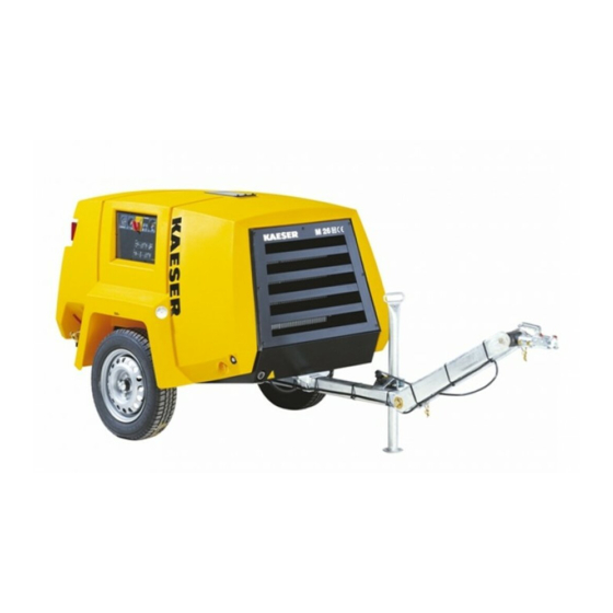
Sign In
Upload
Manuals
Brands
KAESER Manuals
Air Compressor
M26
KAESER M26 Manuals
Manuals and User Guides for KAESER M26. We have
1
KAESER M26 manual available for free PDF download: Service Manual
KAESER M26 Service Manual (208 pages)
Screw
Brand:
KAESER
| Category:
Air Compressor
| Size: 6.16 MB
Table of Contents
Table of Contents
2
Regarding this Document Using the Document
9
Further Documents
9
Copyright
9
Symbols and Identification
9
Warnings
9
Other Instructions and Symbols
10
Tab. 1 the Levels of Danger and Their Meaning
10
Technical Data Nameplate
11
Options
11
Tab. 2 Nameplate
11
Tool Lubricator
12
Non-Return Function
12
Fuel Filter with Water Trap
12
Tab. 3 Combined Label for Coupling Load and Options Fitted
12
Tab. 4 Tool Lubricator
12
Tab. 5 Non-Return Function
12
Tab. 6 Fuel Filter with Water Trap
12
Low Temperature Equipment
13
Equipment for Fire Hazard Areas
13
Sealed Floor Pan
13
Chassis
13
Tab. 7 Low Temperature Equipment
13
Tab. 8 Equipment for Fire Hazard Areas
13
Tab. 9 Sealed Floor Pan
13
Lighting
14
Hose Reel
14
Anti-Theft Device
14
Machine (Without Options)
14
Sound Emission
14
Tab. 11 Lighting
14
Tab. 12 Hose Reel
14
Tab. 13 Anti-Theft Device
14
Torques
15
Ambient Conditions
15
Dimensions
15
Tab. 14 Sound Emission
15
Tab. 15 Sound Pressure Level
15
Tab. 16 Torques for Hex-Head Screws
15
Tab. 17 Ambient Conditions
15
Chassis
16
Weights
16
Tires
16
Wheel Fixing Tightening Torque
16
Compressor
16
Working Pressure and FAD
16
Tab. 10 Chassis
16
Tab. 18 Machine Weights
16
Tab. 19 Tires
16
Tab. 20 Wheel Nut/Bolt Tightening Torque
16
Compressed Air Outlet
17
Pressure Relief Valve
17
Temperature
17
Cooling Oil Recommendation
17
Tab. 22 Compressed Air Distributor
17
Tab. 23 Relief Valve Activating Pressure
17
Tab. 24 Airend Discharge Temperature
17
Tab. 25 Machine Temperatures
17
Cooling Oil Charge
18
Engine
18
Engine Specification
18
Tab. 26 Cooling Oil Recommendation
18
Tab. 27 Cooling Oil Charge
18
Tab. 28 Engine Specification
18
Oil Recommendation
19
Engine Coolant Recommendation
19
Fluid Volumes
19
Battery
19
Tab. 29 Engine Oil Recommendation
19
Tab. 30 Engine Fluid Volumes
19
Options
20
Tool Lubricator
20
Low Temperature Equipment
20
Air Hose with Hose Reel
20
Tab. 32 Road Breaker Lubricant Recommendation
20
Tab. 33 Ambient Conditions
20
Tab. 34 Antifreeze Recommendation
20
Tab. 35 Coolant Pre-Heater
20
Tab. 36 Additional Discharge Valve for the Compressed Air Hose
20
Safety and Responsibility Basic Information
22
Specified Use
22
Improper Use
22
User's Responsibilities
22
Observe Statutory and Universally Accepted Regulations
22
Defining Personnel
23
Adherence to Inspection Schedules and Accident Prevention Regulations
23
Dangers
24
Safely Dealing with Sources of Danger
24
Tab. 37 Inspection Intervals According to Ordinance on Industrial Safety and Health
24
Safe Machine Operation
26
Organizational Measures
28
Danger Areas
28
Tab. 38 Danger Areas
28
Safety Devices
29
Safety Signs
29
Fig. 1 Location of Safety Signs
29
In Emergency
32
Correct Fire Fighting
32
Contact with Operating Materials
32
Tab. 39 Safety Signs
32
Warranty
33
Environmental Protection
33
Design and Function Bodywork
34
Fig. 2 Overview Bodywork
34
Component Identification
35
Fig. 3 Side View (Canopy Removed)
35
Tab. 31 Battery
35
Machine Function
36
Fig. 4 General Design
36
Operating Modes and Control Modes
37
Operating Modes
37
MODULATING Control
38
Safety Devices
38
Monitoring Functions with Shutdown
38
Further Safety Devices
38
Options
38
Environmental Protection Equipment
38
Tool Lubricator
39
Fig. 5 Tool Lubricator
39
Low Temperature Equipment
40
Fig. 6 Frost Protector
40
Option for Operating in Fire Hazard Areas
41
Fig. 7 Coolant Pre-Heating
41
Fuel Filter with Water Trap
42
Optional Anti-Theft Device
42
Transportation Option
42
Tab. 40 Chassis - Overview
43
Tab. 41 Stationary Machines
43
Installation and Operating Conditions
44
Safety
44
Installation Conditions
44
Fig. 8 Minimum Distance from Excavations/Slopes and Walls
44
Installation Safety
46
Reporting Transport Damage
46
Adjusting the Chassis
46
Tab. 42 Height Adjustable Towbar
46
Adjusting the Towbar Height
47
Fig. 9 Height Adjustable Towbar Sa
47
Adjusting the Towbar Height
48
Fig. 10 Towbar Height Adjustment Sb
49
Changing the Towing Eye or Coupling
50
Tab. 43 Choice of Ball Couplings
50
Fig. 11 Change from Eye to Ball Coupling (Height Adjustable Towbar)
51
Fig. 12 Change from Eye to Ball Coupling (Height Adjustable Towbar with Overrun Brake)
53
Fig. 13 Change from Eye to Ball Coupling (Fixed Height Towbar)
55
Initial Start-Up Safety
57
Instructions to be Observed before Commissioning or Recommissioning
57
Checking Positioning and Operating Conditions
57
After Storing the Machine for a Long Period
58
Low-Temperature Operation (Winter)
58
Tab. 44 Positioning and Operating Conditions Checklist
58
Tab. 45 Measures for Re-Commissioning the Compressor after a Long Period of Storage
58
Starting Assistance
59
Fig. 14 Jumper Cable Connection Diagram
59
Starting up Low-Temperature Equipment
60
Tab. 46 Low-Temperature Equipment Checklist
61
Operation
62
Starting and Stopping
62
Starting
62
Fig. 15 Instrument Panel and "Control ON" Switch
62
Allow the Machine to Run up to Operating Temperature
63
Shutting down
63
Fig. 16 Warm-Up Period When Ambient Temperatures Are below 14 °F
63
Operating the Tool Lubricator
64
Using the Low-Temperature Equipment
64
Using the Frost Protector
64
Fig. 17 Setting the Tool Lubricator
64
Coolant Pre-Heating
65
Fig. 18 Switching on the Frost Protector
65
Using the Hose Reel
66
Using the Hose Reel (EC Version)
66
Fig. 19 Hose Reel (EC Design)
66
Fault Recognition and Rectification
68
Basic Instructions
68
Engine Faults and Alarms
68
Engine Refuses to Start or Comes to a Stop
68
Engine Does Not Reach Full Speed
69
Indicator Lamp Remains on
69
Tab. 47 Alarm: Engine Refuses to Start or Comes to a Stop
69
Tab. 48 Alarm: Engine Does Not Reach Full Speed
69
Tab. 49 Indicator Lamp Remains on
69
Compressor Faults and Alarms
70
Working Pressure too High
70
Working Pressure too Low
70
Tab. 50 Fault: Working Pressure too High
70
Tab. 51 Fault: Working Pressure too Low
70
Pressure Relief Valve Blowing off
71
Machine Overheating
71
Tab. 52 Fault: Pressure Relief Valve Blowing off
71
Tab. 53 Fault: Machine Overheating
71
Too Much Oil Residue in the Compressed Air
72
Oil Flows from the Compressor Air Filter after Shutdown
72
Tab. 54 Fault: too Much Oil Residue in the Compressed Air
72
Tab. 55 Fault: Oil Flows from the Compressor Air Filter after Shutdown
72
10.1 Maintenance
73
Safety
73
Maintenance Schedules
73
Logging Maintenance Work
73
Maintenance Tasks after Commissioning
74
Regular Maintenance Tasks
74
Tab. 56 Maintenance Tasks after Commissioning
74
Tab. 57 Maintenance Intervals and Regular Maintenance Tasks
74
Maintenance Schedule
75
Maintenance Schedule for Options
77
Tab. 58 Regular Maintenance Tasks
77
Engine
78
Cooler Maintenance
78
Tab. 59 Regular Maintenance Task Options
78
Fig. 20 Checking Coolant Level
79
Tab. 60 Coolant Frost Protection
80
Air Filter Maintenance
81
Fig. 21 Draining the Coolant from the Radiator
81
Fig. 22 Engine Air Filter Maintenance
82
Fuel System Maintenance
83
Fig. 23 Bleeding the Fuel System
84
Fig. 24 Checking the Securing Strap
86
Fig. 25 Fuel Filter with Water Trap
87
Changing the Engine Oil
88
Fig. 26 Changing the Engine Oil
89
Fig. 27 Detail Oil Drain Valve
89
Tab. 61 Oil Drain Valve
89
Changing the Engine Oil Filter
91
Fig. 28 Changing the Engine Oil Filter
91
Checking the Drive Belts
92
Battery Maintenance
93
Fig. 29 Belt Tension Checking by Hand
93
Fig. 30 Warning Stickers on the Battery
94
Compressor
96
Checking Cooling Oil Level
96
Topping up the Cooling Oil
97
Fig. 31 Checking Cooling Oil Level
97
Changing the Cooling Oil
98
Fig. 32 Changing the Cooling Oil
99
Changing the Oil Filter
100
Fig. 33 Changing the Oil Filter
100
Changing the Oil Separator Cartridge
101
Fig. 34 Changing the Oil Separator Cartridge
102
Fig. 35 Oil Separator Tank Dirt Trap Maintenance
103
Air Filter Maintenance
104
Fig. 36 Compressor Air Filter Maintenance
104
Pressure Relief Valve Checking
105
Clean Cooler/Radiator
105
Fig. 37 Clean Cooler/Radiator
106
Chassis
107
Wheel Checks
107
Tow-Bar Maintenance
107
Overrun Braking Mechanism Maintenance
107
Greasing the Brake Rods
108
Checking Brake Linings
108
Tab. 62 Overrun Brake Mechanism Lubricating Point
108
Greasing the Canopy Hinges
109
Fig. 38 Checking the Brake Lining Thickness
109
Fig. 39 Lubricating the Canopy Hinges
109
Maintain Rubber Sealing Strips
110
Options
110
Tool Lubricator Maintenance
110
Frost Protector Maintenance
111
Fig. 40 Tool Lubricator Maintenance
111
Fig. 41 Filling the Frost Protector
112
Spark Arrestor Cleaning
113
Fig. 42 Spark Arrestor Cleaning
113
Document Maintenance and Service Work
115
Tab. 63 Logged Maintenance Tasks
115
11 Spares, Operating Materials, Service
116
Note the Nameplate
116
Ordering Consumable Parts and Operating Fluids/Materials
116
Tab. 64 Compressor Consumables
116
Tab. 65 Consumable Engine Parts
116
Kaeser Air Service
117
Service Addresses
117
Spares for Service and Repair
117
Decommissioning, Storage and Transport 12.1 De-Commissioning
173
Temporary Decommissioning
173
Tab. 66 "Temporarily Decommissioned" Information Notice
173
Long-Term Decommissioning
174
Tab. 67 Long-Term Decommissioning Checklist
174
Transporting
175
Towing the Compressor on the Road
175
Tab. 68 "Long-Term Decommissioned" Information Notice
175
Fig. 43 Towing Alignment
176
Fig. 44 Ball Coupling Function
177
Fig. 45 Safety Sign - Secure the Chocks
178
Parking the Compressor
179
Fig. 46 Breakaway Cable Attachment
179
Fig. 47 Injury Can Occur if the Towbar Is Unsupported and Allowed to Fall
180
Fig. 48 Safety Sign - Secure the Chocks
180
Transporting with a Crane
182
Transporting with a Forklift Truck
182
Transporting as a Load
183
Fig. 49 Transport Using a Forklift Truck
183
Fig. 50 Load Secured by Straps
183
Storage
184
Disposal
184
Annex 13.1 Marking
186
Pipeline and Instrument Flow Diagram (P+I Diagram)
186
Fig. 51 Marking
186
Dimensional Drawing
190
Dimensional Drawing - Fixed Height Towbar Without Parking Brake
190
Dimensional Drawing - Stationary Machine with Skids
192
Electrical Diagram
194
Lighting and Signaling System Connection
203
Fuel Circulation Diagram
208
Advertisement
Advertisement
Related Products
KAESER M122
KAESER M43
KAESER M27
KAESER M135 SIGMA CONTROL MOBIL
KAESER M 64
KAESER M100
KAESER Aircenter SX 3
KAESER Aircenter SX 4
KAESER Aircenter SX 5
KAESER Aircenter SX 7.5
KAESER Categories
Air Compressor
Compressor
Dryer
Construction Equipment
Controller
More KAESER Manuals
Login
Sign In
OR
Sign in with Facebook
Sign in with Google
Upload manual
Upload from disk
Upload from URL