Sign In
Upload
Manuals
Brands
JYTEK Manuals
Measuring Instruments
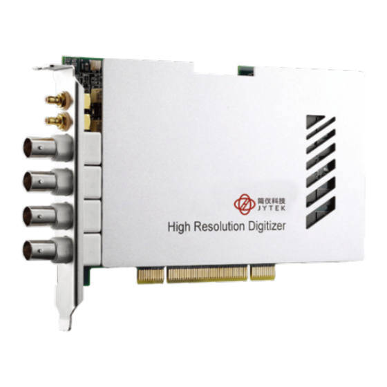
PXI-69816D
JYTEK PXI-69816D Manuals
Manuals and User Guides for JYTEK PXI-69816D. We have
1
JYTEK PXI-69816D manual available for free PDF download: User Manual
JYTEK PXI-69816D User Manual (48 pages)
Brand:
JYTEK
| Category:
Measuring Instruments
| Size: 2 MB
Table of Contents
Getting Service
2
Table of Contents
3
Introduction
7
1�1 Features
8
Applications
8
Specifications
9
Table 1-1: Analog Input Specifications
9
Table 1-2: Offset and Gain Error
9
Table 1-3: -3Db Bandwidth, Typical
10
Figure 1-1: PCI/PXI-69816 Bandwidth Chart (50 Ω Input Impedance)
10
Table 1-4: System Noise
11
Figure 1-2: PCI/PXI-69826 Bandwidth Chart (50 Ω Input Impedance)
11
Figure 1-3: PXI-69846 Bandwidth Chart (50 Ω Input Impedance)
11
Table 1-5: Spectral Characteristics - PCI/PXI-69816
12
Figure 1-4: PXI-69816 FFT with ±0.2 V Input Range
12
Table 1-6: Spectral Characteristics - PXI-69826
13
Figure 1-5: PXI-69816 FFT with ±1 V Input Range
13
Figure 1-6: PXI-69826 FFT with ±0.2 V Input Range
14
Figure 1-7: PXI-69826 FFT with ±1 V Input Range
14
Table 1-7: Spectral Characteristics - PCI/PXI-69846
15
Figure 1-8: PXI-69846 FFT with ±0.2 V Input Range
15
Figure 1-9: PXI-69846 FFT with ±1 V Input Range
16
Table 1-9: Triggering
18
Table 1-10: Data Storage and Transfer
18
Table 1-11: Onboard Reference
18
Table 1-12: General Information
19
Getting Started
20
Installation Environment
20
2�2 Package Contents
20
2�3 Mechanical Drawing and I/O Connectors
21
Figure 2-1: PXI-698X6 Mechanical Drawing
21
Figure 2-2: PCI-698X6 Mechanical Drawing
21
Table 2-1: Connector Pin Assignments
22
Installing the Module
23
Software Support
24
2�5�1 WD-DASK (Legacy Drivers and Support)
24
Figure 2-3: Legacy Software Support Overview
24
Operation Theory
25
Functional Block Diagram
25
Figure 3-1: PCI-698X6 Functional Block Diagram
25
Figure 3-2: PCI-698X6 Functional Block Diagram
25
Basic AI Acquisition
26
3�2�1 Analog Input Path
26
Basic Acquisition Timing
26
Figure 3-3: Analog Input Signal Block Diagram
26
Table 3-1: Basic Counters
27
AI Data Format
28
Table 3-2: AI Data Format
28
Figure 3-4: Basic Acquisition Timing of Digitizer
28
ADC Sampling Rate and TIMEBASE Control
29
3�3�1 Internal Oscillator
29
External Clock through Front Panel
29
Figure 3-5: PCI/PXI-698X6 Timebase Source and Architecture
29
External Clock from PXI Interfaces
30
Sampling Rate Control
30
Timebase Exporting
30
Figure 3-6: Configuring Different Sampling Rate of a Digitizer
30
3�4 Trigger Sources
31
Software Trigger
31
External Digital Trigger
31
Figure 3-7: PCI/PXI-698X6 Trigger Architecture
31
Figure 3-8: External Digital Trigger Polarity and Pulse Width Requirement
31
3�4�3 Analog Trigger
32
Table 3-3: Ideal Transfer Characteristics for Analog Triggers
32
Figure 3-9: Analog Trigger Conditions
32
PXI STAR Trigger
33
PXI Trigger Bus
33
Trigger Signal Exporting
33
Figure 3-10: TRG IO Output Signal Timing
33
3�5 Trigger Modes
34
Post-Trigger Acquisition
34
Pre-Trigger Acquisition
34
Figure 3-11: Post-Trigger Acquisition
34
Figure 3-12: Pre-Trigger Mode Operation
34
Middle-Trigger Acquisition
35
Delay-Trigger Acquisition
35
Figure 3-13: Pre-Trigger Mode Operation
35
Figure 3-14: Middle-Trigger Mode Operation
35
Post-Trigger or Delay-Trigger Acquisition with Retrigger
36
Figure 3-15: Delay-Trigger Mode Operation
36
Figure 3-16: Re-Trigger Mode Operation
36
3�6 Data Transfers
37
Figure 3-17: Scatter-Gather DMA for Data Transfer
37
Synchronizing Multiple Modules
38
Figure 3-18: SSI Architecture
38
Table 3-4: Summary of SSI Timing Signals and the Corresponding Function
38
Figure 3-19: SSI Connector Location on the PCI-69816/26/46
39
Figure 3-20: Installation of ACL-SSI-2 Cable
39
Ssi_Timebase
40
Ssi_Trig1
40
Table 1-8: Timebase
40
Table 3-5: SSI Signal Locations and Pin Definition
40
Figure 3-21: SSI_TRIG1 Input and Output Timing Characteristics
41
Figure 3-22: SSI_TRIG2 Output Timing
41
SSI_TRIG2 and SSI_START_OP
41
Figure 3-23: SSI_TRIG2 Input Timing Requirement
42
Figure 3-24: SSI_START_OP Output and Input Timing Characteristics
42
Comparing the Different Trigger Sources from SSI
43
Physical Location of the PXI and PCI Digitizer
44
Identify PXI Digitizer's Physical Location by Geographic Address
44
Assign a Board ID to a PCI Digitizer
44
Figure 3-25: the Location of Board ID Switch
44
Figure 3-26: Enlargement of Board ID Setting
45
Table 3-6: Board ID Combination Conditions
46
Important Safety Instructions
47
Advertisement
Advertisement
Related Products
JYTEK PXI-69826D
JYTEK PXI-69846D
JYTEK PXI-69846W
JYTEK PXI-69846H
JYTEK PXIe-69834
JYTEK PXIe-69852
JYTEK PCIe-69814 Series
JYTEK PCIe-69814P
JYTEK PCI-69846D
JYTEK PCI-69846H
JYTEK Categories
Computer Hardware
Control Unit
Controller
Measuring Instruments
Chassis
More JYTEK Manuals
Login
Sign In
OR
Sign in with Facebook
Sign in with Google
Upload manual
Upload from disk
Upload from URL