Sign In
Upload
Manuals
Brands
JUMO Manuals
Controller
TYA S202
JUMO TYA S202 Manuals
Manuals and User Guides for JUMO TYA S202. We have
1
JUMO TYA S202 manual available for free PDF download: Operating Manual
JUMO TYA S202 Operating Manual (99 pages)
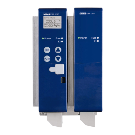
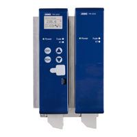
Thyristor power controller in a three-phase economy circuit
Brand:
JUMO
| Category:
Controller
| Size: 4 MB
Table of Contents
Table of Contents
3
1 Introduction
9
Preface
9
Typographical Conventions
10
Warning Symbols
10
Note Symbols
10
Performing an Action
11
Display Types
11
Order Details
12
Scope of Delivery
12
Accessories
12
General Accessories
13
Brief Description
14
Standards, Approvals, and Conformity
15
2 Mounting
17
Important Installation Notes
17
Environmental Influences
18
Filtering and Interference Suppression
19
Admissible Load Current Depending on the Ambient Temperature and the Site Altitude
19
Wall Mounting with Screws (Default)
21
Mounting on DIN Rail (Accessories)
24
Dimensions
25
Type 709066/X-0X-020-0X-XXX-XX
25
Type 709066/X-0X-032-0X-XXX-XX
26
Type 709066/X-0X-050-0X-XXX-XX
27
Type 709066/X-0X-100-0X-XXX-XX
28
Type 709066/X-0X-150-0X-XXX-XX
29
Type 709066/X-0X-200-0X-XXX-XX
29
Clearances (All Types)
30
Type 709066/X-0X-250-0X-XXX-XX
30
3 Electrical Connection
31
Pluggable Screw Terminals with 20 a
31
Type 709066/X-0X-20-0X-XXX-XX
31
Cable Lugs and Pluggable Screw Terminals from 32 a
32
Type 709066/X-0X-032-0X-XXX-XX
33
Type 709066/X-0X-050-0X-XXX-XX
33
Type 709066/X-0X-100-0X-XXX-XX
35
Type 709066/X-0X-150-0X-XXX-XX
37
Type 709066/X-0X-200-0X-XXX-XX
37
Type 709066/X-0X-250-0X-XXX-XX
38
Connection Diagram
39
Rotary Current Economic Circuit Master-Slave for Resistive Loads in Star-, Delta Connection or Transformer Loads (Resistive-Induktive)
41
Switch-On Sequence
41
4 Operation
43
Display after Switching on the Device
43
Display and Control Elements
44
Appearance of Measured Values
44
Meaning of the Displayed Measured Values
45
Appearance in the Configuration Level
47
Appearance of Error Messages and Special Statuses
47
Operating Level
48
Device Data
48
Power Controller
49
Setpoint Value Configuration
49
Monitoring
50
5 Configuration
53
Configuration Level
53
Device Data
54
Language Wizard Active
54
Temperature Unit
54
Display Contrast
54
Switch-Off
54
Display Lighting
54
Apply Default Settings
54
Power Controller
54
Thyristor Control
54
Cycle Time
55
Min. on Period
55
Α Start
55
Α Start Angle
55
Soft Start
55
Soft Start Type
56
Soft Start Duration
56
Current Limiting
56
Dual Energy Management
57
Analog Inputs
58
Current Measuring Range
58
Current Measuring Range, Start
58
Current Measuring Range, End
58
Voltage Measuring Range
58
Voltage Measuring Range, Start
58
Voltage Measuring Range, End
58
Setpoint Value Configuration
59
Setpoint Specification
59
Input in the Event of an Error
59
Value in the Event of an Error
59
Base Load
59
Monitoring
60
Limit Value Monitoring
60
Min. Limit Value Alarm
60
Max. Limit Value Alarm
60
Limit Value Hysteresis
61
Load Monitoring
61
Limit Value Load Monitoring
61
Load Type Load Monitoring
61
Teach-In Type Load Monitoring
61
Monitoring of the Mains Voltage Drop
61
Digital Inputs
62
Inhibit Input Control Direction
62
Digital Output
63
Output Mode
63
Control Direction, Digital Output
63
Rs422/485
63
Baud Rate
64
Data Format
64
Device Address
64
Min. Response Time
64
Changing Codes
64
Code, Manual Mode
64
Code, Operating Level
64
Code, Config. Level
64
Configuration Example
65
6 Special Device Functions
67
Detection of Load Faults
67
Teach-In
69
Manual Mode
70
Setpoint Specification in Manual Mode
70
Configuring Teach-In (Prerequisite for Teach-In in Manual Mode)
70
Performing Teach-In in Manual Mode
71
Setpoint Specification Via Potentiometer
72
Dual Energy Management
72
Α Start
74
Monitoring of the Mains Voltage Drop
75
Firing Pulse Inhibit
75
Thyristor Control Logic (Switch)
76
7 Setup Program
77
Hardware
77
Compatible Operating Systems
77
Installation
78
Program Start
80
Forgotten the Code
81
Changing the Language of the Device Texts
82
8 Error Messages and Alarms
83
Binary Signal for Collective Fault
86
Replacing a Defective Semiconductor Fuse
87
Accessories: Semiconductor Fuses
88
Semiconductor Fuses Type 709066/X-0X-20
88
Semiconductor Fuses Type 709066/X-0X-32
89
9 What to Do, if
91
10 Technical Data
93
Voltage Supply, Fan Specifications at 250 A, Load Current
93
Galvanic Isolation
93
Analog Inputs (Master Only)
93
Display and Measuring Accuracy
94
Binary Output (Fault Signal Output Master Only)
94
General Specifications
94
Approvals/Approval Marks
97
Advertisement
Advertisement
Related Products
JUMO TYA S201
JUMO TYA 202
Jumo TYA 201
JUMO mTRON T 570
JUMO mTRON T 350
JUMO dTRANS T08 13
JUMO dTRANS T03 TU
JUMO dTRANS T03 B
JUMO dTRANS T03 BU
JUMO tecLine PAA
JUMO Categories
Transmitter
Measuring Instruments
Controller
Thermostat
Voice Recorder
More JUMO Manuals
Login
Sign In
OR
Sign in with Facebook
Sign in with Google
Upload manual
Upload from disk
Upload from URL