Sign In
Upload
Manuals
Brands
JUKI Manuals
Sewing Machine
MOL-254
JUKI MOL-254 Manuals
Manuals and User Guides for JUKI MOL-254. We have
6
JUKI MOL-254 manuals available for free PDF download: Handbook, Engineer's Manual, Manual, Instruction Manual
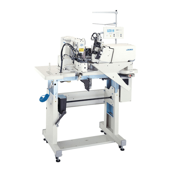
JUKI MOL-254 Engineer's Manual (234 pages)
2-needle, Automatic Belt-loop Attaching Machine
Brand:
JUKI
| Category:
Sewing Machine
| Size: 3.04 MB
Table of Contents
Table of Contents
3
Specifications
8
Names and Functions of Components
10
Names and Functions of the Main Unit
10
Names and Functions of Operation Box Panel
11
Timing Chart
13
Standard Adjustment
14
Machine Head Components
14
Adjustment of the Main Shaft Components
14
Removing the Play of Main Shaft
14
Installing the Main Shaft Coupling
14
Adjusting the Main Shaft Sensor
16
Stretching the Timing Belt (Main Shaft-To-Hook Driving Shaft for the Front Side Timing)
16
Adjusting the Idler
18
Adjusting the Hook Driving Shaft Components
18
Adjusting the Longitudinal Position of the Oscillator
18
Adjusting the Backlash of the Oscillator Gear
20
Removing the Play of the Hook Driving Shaft
20
Adjusting the Thread Trimmer Mechanism Components
22
Adjusting the Position of the Thread Trimmer Cam
22
Adjusting the Thread Trimmer Link Stopper Screw
22
Adjusting the Thread Trimming Cylinder (Front Side)
24
Position of the Thread Trimmer Shaft
26
Position of the Cam Follower Stopper
26
Position of the Thread Trimming Solenoid
28
Adjusting Moving and Counter Knives
30
Height of the Moving and Counter Knives
32
Parallelism of the Blade Tip of the Counter Knife
32
Adjusting the Thread Trimmer Cam Timing (Only for this Side)
34
Adjusting the Tension Release Mechanism Components
34
Installing Position of the Tension Release Notch
34
Position of the Tension Release Stopper
36
Releasing Amount of the Thread Tension Disk
36
Adjusting the Sensor Components
38
Adjusting the y Origin Sensor
38
Adjusting the X Origin Sensor
38
Adjusting the Feed Mechanism Components
40
Adjusting the Position of the X/Y Motors
40
Adjusting the Position of the Cloth Presser Foot
42
Adjusting the Position of the Cloth Presser Lower Plate
44
Adjusting the Lift of the Cloth Presser Foot
44
Adjusting the Position of the Needle Bar and the Hook
46
Adjusting the Height of the Needle Bar
46
Changing the Position of the Throat Plate (Hook Base) (Adjustment of the 1St Hook)
46
Adjusting Needle-To-Inner Hook Timing (same Adjustment for this Side and Far Side)
48
Adjusting the Position of the Shuttle Upper Spring (same Adjustment for this Side and Far Side)
50
Form of the Inner Hook Presser
50
Adjusting the Timing of the Hook on this Side
52
Adjusting Procedure of the Hook Removing Sensor
54
Adjusting the Play in the Hook Removing Ball Screw
56
With Regard to Sewing
58
Adjusting the Thread Take-Up Spring
58
Adjusting the Position of the Wiper
60
Disassembling/Assembling of Components
62
Disassembling/Assembling of the Timing Belt
62
Disassembling/Assembling of the Throat Plate
76
Disassembling/Assembling of the Hook Removing Cross Roller
78
Disassembling/Assembling of the Ball Spline
80
Device Components
82
Loop Cut Components
82
Adjusting the Height of the Loop Cut Knife Unit
82
Adjusting the Cross Cut Angle of the Loop Cut Knife
84
Adjusting the Position of the Loop Cut Center
86
Changing the Straight Cutting
88
Adjusting the Loop Cut Cylinder Sensor
94
Adjusting the Installation of the Belt Loop Splice Sensor
96
Loop Clamp Feed Components
100
Adjusting the Loop Clamp Base Plate Front Sensor
100
Adjusting the Loop Clamp Base Plate Rear Sensor
102
Adjusting the Loop Clamp Lever Loop Existence Sensor
104
Adjusting the Opening Amount of the Loop Clamp Base
106
Adjusting the Position of the Loop Clamp Feed Unit
106
Belt Loop Feed Components
108
Adjusting the Height (Clearance) of the Loop Feed Roller
108
Adjusting the Pressure of the Loop Feed Roller
110
Adjusting the Tension of the Loop Feed Roller Belt
112
Belt Loop Supply Components
114
Adjusting the Tension of the Loop Supply Belt
114
Adjusting the Play in the Rotation of the Loop Supply Slide Base
116
Adjusting the Loop Supply Slide Base Sensor
118
Adjusting the Height of the Fork (Up/Down of this Side and Far Side)
120
Adjusting the Height of the Fork (Up/Down of the Unit)
122
Adjusting the Position of the Fork and the Needle
124
Adjusting the Air Speed Controller
126
Cam Up/Down Cylinder
126
Belt Presser Removing Base Cylinder
126
Belt Presser Cylinder
126
Loop Pull-Out Cylinder (Optional)
128
Fullness Cylinder (Optional)
128
Needle Cooler (Optional)
128
Adjusting the Pressure Reduction Controller
130
Loop Folding Cylinder
130
Disassembling/Assembling
132
Disassembling/Assembling of the Loop Cut Knife and the Counter Knife
132
Disassembling/Assembling of the Loop Cut Knife Drive Components
134
Disassembling/Assembling of the Loop Supply
136
Disassembling/Assembling of the Loop Supply Cam Components
138
Disassembling/Assembling of the Loop Supply Belt Components
140
Disassembling/Assembling of the Loop Supply Unit
142
Disassembling/Assembling of the Loop Feed Roller Components
144
Disassembling/Assembling of the Belt Presser Unit
146
Installing of the Optional Parts
148
Installing of the Fullness Device
148
Installing of the Needle Cooler
152
Installing of the Thread Breakage Detector Device
154
Installing of the Loop Pull-Out Device
156
Installing of the Air Gun
158
Operation Box Panel
160
Operating Procedure of the Maintenance Screen
160
[CA] Setting of Starting Angle of the 1St Hook Thread Trimming Cylinder Drive
160
[CB] Setting of Ending Angle of the 1St Hook Thread Trimming Cylinder Drive
160
[CC] Setting of Starting Angle of the 2Nd Hook Thread Trimming Solenoid Drive
160
[CD] Setting of the Speed of the Loop Clamp Feed Unit
160
[CE] Setting of the Machine Head X-Y Drive Timing
160
[CF] Setting of the Period of Time During Which the Cloth Presser Foot Stops
161
[CG] Setting of Traveling Backward Distance of the Fork at Low Speed at the Time of Set Back
161
[CH] Setting of the Length of Time at the Time of Change-Over of the Supply Slide Base Cam
161
[CI] Setting of Waiting Time When the Supply Slide Base Travels Backward to the End
161
[CJ] Function of Individual Operation of the Machine Head
162
[CK] Setting of the Number of Revolutions of the Machine Head Motor
162
[CL] Setting of the Machine Head Motor Operating Time
162
[CM] Setting of the Machine Head Motor Stop Time
162
[CN] Setting of the Position Compensation of the Machine Head and the Supply Device
162
Initial Setting Table
163
Dip Switches on the Circuit Board
165
DIP Switches on MAIN Circuit Board
165
DIP Switches on SDC Circuit Board
166
Parts to be Applied with Grease and Locktite Paint
167
Needle Bar Components
167
Main Shaft Components
168
Feed Mechanism Components
169
Tension Release and Thread Trimmer Mechanism Components
170
Thread Presser Components
171
Hook Base Components (1)
172
Hook Base Components (2)
173
Hook Driving Shaft Components
174
Hook Move Components
175
Belt Loop Supply Components
176
Belt Receiver Components
177
Belt Loop Feed Components
178
Clamp Feed Components
179
Knife Components
180
Supplying Device Base Components
181
Pneumatic Circuit Diagram
182
Control Box
183
Explanation of Components
183
Main Circuit Board
184
Sdc Circuit Board
185
Power Circuit Board
186
PMDC Circuit Board
186
Transformer
186
Fan Motor
186
Power Change-Over Tap
186
F1 Fuse (6.3AT)
186
F5 Fuse (6.3AT)
186
F6 Fuse (6.3AT)
186
Replacing the Parts
187
Replacing EPROM
187
Replacing the Fuse
188
Change of the Power Specifications
189
[General Export]
189
Setting of the Power Voltage Specifications
189
Setting of the Phase of Power (Remodelling of the Power Cord)
189
[For CE and General Export, High Voltage]
190
Setting of the Power Voltage Specifications
190
Setting of the Phase of the Power (Remodelling of the Power Cord)
191
Power Switch
192
Power Switch for Domestic and General Export (Low Voltage)
192
Power Switch for General Export (Low Voltage)
192
Power Switch for CE Marking and General Export (High Voltage)
193
Power Switch for CE Marking
193
Name and Installing Position of the Switch Sensor
194
Circuit Diagram
195
Block Diagram
195
Wiring Diagram
198
Power Cable Asm. Circuit Diagram a (for Domestic and General Export (Low Voltage))
198
Power Cable Asm. Circuit Diagram B (for CE and General Export (High Voltage))
198
Transformer Asm. Circuit Diagram
198
DC Power Cable Asm. Circuit Diagram
199
SDC•I/F Cable Asm. Circuit Diagram
199
PMDC•I/F Cable Asm. Circuit Diagram
200
CN10 Wiring Cable Circuit Diagram
200
CN13 Wiring Cable Circuit Diagram
200
CN15 Wiring Cable Circuit Diagram
200
CN11 Wiring Cable Circuit Diagram
201
CN12 Wiring Cable Circuit Diagram
201
CN14 Wiring Cable Circuit Diagram
202
X/Y Table Origin Sensor Wiring Cable Circuit Diagram
203
SDET Sensor Wiring Cable Circuit Diagram
203
Stepping Motor Wiring Cable Circuit Diagram
204
X/Y Table Stepping Motor Wiring Cable Circuit Diagram
204
Fork Move Servo Motor Wiring Cable Circuit Diagram
205
Thread Trimming Mg. Wiring Cable Circuit Diagram
205
Solenoid Valve Wiring Cable Circuit Diagram
206
Sensor Input/Output Table
207
Troubles and Corrective Measures
208
Machine Head Components
208
Device Components
220
Trouble and Corrective Measure
220
Corrective Measures for the Dog-Eared Belt Loop
226
Electrical Components
228
Advertisement
JUKI MOL-254 Handbook (272 pages)
JUKI Industrial Sewing Machines Handbook
Brand:
JUKI
| Category:
Sewing Machine
| Size: 5.52 MB
Table of Contents
Specifications
3
Control Panel Specifications
8
Optional Gauges
37
Guide, Ruler
61
Sewing Pattern
71
Replaceable Gauge Table
105
Machine Head
130
Control Box
130
Computer-Controlled, High-Speed Bartacking Machine
133
Exchanging Parts
153
Needle Thread Clamp Device
163
Options
163
Service Patterns
170
Programming Functions
172
Machine Head
175
Control Panel
184
Production Capacity
195
Sewing Machine Components
207
Gauge Parts
233
Control Panel Specifications
259
Applicable Model
264
Major Functions
264
JUKI MOL-254 Handbook (257 pages)
Industrial Sewing Machines
Brand:
JUKI
| Category:
Sewing Machine
| Size: 5.2 MB
Table of Contents
Specifications
3
Sewing Pattern
64
Operation Panel
116
Table of the Work Clamp Foot
122
Throat Plate
137
Gauge Parts
229
Advertisement
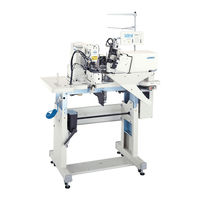
JUKI MOL-254 Instruction Manual (110 pages)
2-needle, automatic belt-loop attaching machine
Brand:
JUKI
| Category:
Sewing Machine
| Size: 5.68 MB
Table of Contents
Important Safety Instructions
6
Contents
13
Specifications
17
Names and Functions of Components
22
Installation
24
Fixing the Table Stand
24
Installing the Thread Stand
24
Air Adjustment
25
Removing the Head Fixing Bolt
25
Installing the Bobbin Winder
25
Adjusting the Height of the Table
26
Preparation
27
Lubrication
27
Machine Head
27
Hook Race Surface
27
Crank Rod Lubricating Plate
28
Main Shaft Front Bushing Portion
28
Loop Supplying Device
29
Lubrication Method
29
Passing a Belt Loop
30
Attaching the Needle
31
Setting the Bobbin Case
32
Winding the Bobbin Thread
34
Setting the Bobbin into the Bobbin Case
35
Threading the Machine Head
36
Adjusting the Thread Tension
37
Basic Operation Flow Chart
39
Basic Performance
39
Operation
43
Names and Functions of Operation Box Panel
43
Explanation of the Counter
47
Confirmation of Needle Entry Point
50
Setting Screen
51
Selection of the Pattern
52
Setting of Max. Number of Rotations
53
Setting of Number of Stitches
53
Setting of Bartacking Length
53
Setting of Bartacking Width
53
Setting of Belt Loop Width (*1)
54
Fine Adjustment of Bartacking Position (*1)
54
Fullness Setting
55
Max. Loosening Amount
56
Setting of the Belt Loop Splice Detection
57
Setting of the Belt Loop Detection
57
Adjustment Screen
58
Sewing Machine Start-Up Speed
58
List of Display
58
Adjusting the 1St Hook
59
Belt Feedig Amount
60
Setting of Splice Cutting (Front)
60
Setting of Splice Cutting (Rear)
61
Setting of Wiper Operating Time (Unit: MM)
61
X-Axis Origin Compensation of the Sewing Machine Presser (Unit: MM)
62
Y-Axis Compensation of the Sewing Machine Presser (Unit: MM)
62
Fork Origin Compensation
63
Setting of Thread Presser Operation
63
Selection of Check Program Mode
64
Adjustment Data Value at the Time of Delivery
64
Setting of DIP Switches
65
Upper Side of Side Face
65
Lower Side of Side Face
66
Maintenance
68
Changing the Center-To-Center Distance between Bartacks
68
Changing the Space between the Needles
68
Changing the Presser Foot
68
Changing the Cloth Presser Lower Plate
69
Adjusting the 1St Hook Position
69
Adjusting the Wiper
71
In Case of Front Side (in the State Where the Machine Stops)
71
In Case of Rear Side (It Is Not Necessary to Adjust Since Normally, this Wiper Is Fixed.)
71
Adjusting the Fork
72
Moving the Front Side Folding Shaft
72
Changing the Loop Receiver
73
Moving the Loop Feeding Unit
73
Moving the Loop Receiver
73
In Case of the Fullness
74
Change Data Value of Fullness Amount <1H> on the Panel to a Proper Value
74
Adjusting the Width of Belt Loops
75
Changing the Binder
75
Adjusting the Loop Gathering Claw
75
Adjusting the Cross Cut Position
75
Changing the Length of Bartacking
76
Changing the Value of Belt Loop Width
76
Replacing Loop Cut Moving Knife
77
Removing the Moving Knife
77
Adjustment
77
Adjusting the Belt Loop Splice Detector (Adjusting with the Actual Product)
78
Adjusting the Belt Loop Splice Detector
79
Numeric Value Input Method (Applied Volume)
79
Adjustment of the Belt Loop Without Splice
80
Changing the Straight Cutting
81
Removing the Chip Cover
81
Approximate Value
81
Changing the Knife Position
82
Changing the DIP Switch
82
Changing the Belt Feeding Amount
82
Selecting the Folding Fork
83
Replacing the Loop Folding Shaft and Adjusting the Folding Pressure
84
Draining
85
Adjustment of the Height of the Needle Bar
86
Adjusting the Needle-To-Hook Timing
87
Rear Side
87
Front Side
87
Thread Take-Up Spring
89
Adjusting Thread Take-Up Spring (this Side)
89
Adjusting Thread Take-Up Spring (Rear Side)
89
Adjusting the Thread Take-Up Spring Stroke
89
Adjusting the Rising Amount of the Thread Tension Disk
91
Adjusting the Moving and Counter Knives
92
Draining Waste Oil
93
Cleaning the Air Filter
93
Belt Loop Retaining Release Function
94
Alarm List
97
Phenomena, Causes and Corrective Measures or Troubles in Sewing
102
Phenomena, Causes and Corrective Measures of Trouble
106
Optional
109
JUKI MOL-254 Manual (179 pages)
Brand:
JUKI
| Category:
Sewing Machine
| Size: 68 MB
Table of Contents
To Ensure Safe Use of Your Sewing Machine
2
Safety Precautions
3
Maintenance
5
Operating Environment
5
Hazardous Area
6
Safety Devices and Warning Labels
7
Während des Betriebs
11
Wartung
12
Précautions de Sécurité
16
Précautions de Base
16
Installation
17
Precauciones de Seguridad
22
Instalación
23
Mantenimiento
24
Ambiente Operativo
24
Avvertenze Per la Sicurezza
28
Durante Il Funzionamento
29
Manutenzione
30
JUKI MOL-254 Manual (2 pages)
Brand:
JUKI
| Category:
Sewing Machine
| Size: 0.75 MB
Advertisement
Related Products
JUKI MO-6700D Series
JUKI MOJ 2500N series
JUKI MO-634DEV
JUKI MO-654
JUKI MO-634
JUKI MO-804
JUKI MO-3314
JUKI MO-3616
JUKI MO-6800D/DD20 Series
JUKI MOL-254N
JUKI Categories
Sewing Machine
Industrial Equipment
Sewing Machine Accessories
Accessories
Trimmer
More JUKI Manuals
Login
Sign In
OR
Sign in with Facebook
Sign in with Google
Upload manual
Upload from disk
Upload from URL