Sign In
Upload
Manuals
Brands
JUKI Manuals
Sewing Machine
LU-2212N-7
JUKI LU-2212N-7 Manuals
Manuals and User Guides for JUKI LU-2212N-7. We have
2
JUKI LU-2212N-7 manuals available for free PDF download: Engineer's Manual, Brochure & Specs
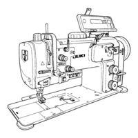
JUKI LU-2212N-7 Engineer's Manual (129 pages)
1/2-NEEDLE, HIGH-SPEED, UNISON-FEED LOCKSTITCH MACHINE WITH VERTICAL-AXIS LARGE HOOK AND AUTOMATIC THREAD TRIMMER/2P DIAL/NEEDLE THREAD CLAMP DEVICE/2P DIAL
Brand:
JUKI
| Category:
Sewing Machine
| Size: 1.79 MB
Table of Contents
Table of Contents
3
Specifications
7
Model Numbering System
8
Lu-2210N/W-7
8
Lu-2212N-7
9
Lu-2260N/W-7
10
Lu-2220N-7
11
Standard Adjustment
12
Types and Names of Gradations on the Hand-Wheel
12
Sewing Speed
13
Needle Entry
14
Needle Entry in the Needle Slot of the Feed Dog in the Lateral Direction
14
Needle Entry in the Needle Slot of the Feed Dog in Feeding Direction (LU-2210N/W-7, 2260N/W-7, 2212N-7)
16
Needle Entry in the Needle Slot of the Feed Dog in Feeding Direction (LU-2220N-7)
18
Needle-To-Hook Relation
20
Height of the Needle Bar
20
Clearance between the Needle and the Blade Point of Hook
22
Timing between the Needle and the Hook
24
Clearance between the Throat Plate and the Inner Hook Stopper
26
Timing of the Cloth Feed Action
28
Horizontal Feed Timing
28
Vertical Feed Timing
28
Upper Feed Timing
30
Height of the Feed Dog
32
Amount of Alternating Vertical Movement of the Walking Foot and Presser Foot (Balance between the Lifting Amounts of the Presser Foot and Walking Foot)
34
Adjustment of the Feed Mechanism
36
Zeroing of the Feed Adjusting Mechanism
36
Stitch Length in the Normal Feed and Reverse Feed
38
Adjustment (for LU-2212N-7 and LU-2220N-7)
40
Position of the Reverse Feed Connecting Arm/The Amount of Condensation
42
Bobbin Winder
44
Bobbin Winder Friction Wheel Adjustment
45
Bobbin Winding Amount Adjustment
45
Thread Trimmer Device (for LU-2210N/W-7 and LU-2260N/W-7)
46
Counter Knife
46
Clamp Spring
46
Knife Pressure
46
Moving Knife Driving Arms A, B and C
46
Thread Trimmer Device (for LU-2212N-7)
48
Positions of Counter Knife and Clamp Spring
48
Counter Knife Base Position
48
Knife Pressure
48
Moving Knife Driving Arms A, B and C
48
Height of the Moving Knife (for the Right-Hand Side Hook) (for LU-2210N/W-7, LU-2212N-7 and LU-2260N/W-7)
51
Height of the Moving Knife (for the Left-Hand Side Hook) (for LU-2260N/W-7)
52
Thread Trimmer Cam (for LU-2210N/W-7 and LU-2260N/W-7)
54
Thread Trimmer Cam (for LU-2212N-7)
56
Thread Trimmer Device (LU-2220N-7)
58
Positioning for the Thread Trimming Cylinder Joint
58
Counter Knife (Adjustment of Movement) (Positioning for the Counter Knife Base Stopper)
60
Counter Knife (Adjustment of Right and Left Positioning)
62
Moving Knife (Adjustment of Vertical Positioning)
64
Counter Knife (Adjustment of Vertical Positioning)
64
Thread Guide Mounting Position
66
Adjustment of Knife Presser
66
Moving Knife Driving Arm and Initial Position of the Moving Knife
68
Adjustment of Gap between the Moving Knife Driving Arm and the Moving Knife Driving Arm Stopper
70
Mounting Position of the Moving Knife Return Plate
70
Adjustment of Timing for the Thread Trimming Cam
70
Clamp Spring Mounting Position
72
Explanation of the Solenoid Valve
74
Opener
76
Timing of the Opener
76
Clearance between the Opener and the Protruding Section of the Inner Hook
76
Presser Lifting Unit
78
Presser Lifting Amount
78
Presser Lifting Cylinder
78
Safety Mechanism
80
Releasing Torque Adjustment
80
How to Reset the Safety Mechanism
80
Lubricating Unit
82
Oil Distribution Diagram
82
Supplying and Replacing Oil
82
Filter Replacement Procedure
84
Adjusting the Amount of Oil in the Hook and Cleaning the Hook Filter
84
Aperture Plate Removal Procedure (for LU-2212N-7)
86
Removal Procedure of Aperture Plate
86
Attachment Procedure of Aperture Plate
86
Adjustment of 2P Cylinder Connecting Link
86
Aperture Plate Removal Procedure (for LU-2220N-7)
88
Removal Procedure of Aperture Plate
88
Attachment Procedure of Aperture Plate
88
Adjustment of 2P Cylinder Connecting Link
88
Various Switches
90
Operation Switches
90
Knee Switch
90
Parts Replacement
92
How to Replace the Needle Clamp (LU-2260N/W-7)
92
Replacement of the Presser Adjusting Spring
94
How to Replace the Timing Belt
96
How to Change from 1-Needle to 2-Needle Specifications (LU-2210N-7 → → → → → LU-2260N-7)
102
Bed Height Adjustment
105
Parts to be Carefully Tightened
106
Parts to be Fixed with LOCK-TITE Paint
107
Maintenance Parts List
108
Mechanism Adjusting Procedure Chart at a Glance
109
Troubles in Sewing and Corrective Measures
111
Related to Sewing
111
Related to Thread Trimmer
117
Replaceable Gauge Table
120
For LU-2210N/W-7, LU-2212N-7 and LU-2220N-7
120
For LU-2260N/W-7
122
(1) Connector from the Machine Head
123
Machine Head Wiring (with Thread Trimmer Only)
123
(LU-2210N/W-7, LU-2260N/W-7 (Other than LU-22*0*-0-*-0B)
123
Connectors from Solenoid Valve (Asm.) (40024969) (LU-2210N/W-7, LU-2260N/W-7 (Other than LU-22*0*-0-*-0B)
123
Connector from the Machine Head (for LU-2210N/W-7, LU-2260N/W-7 (LU-22*0*-0-*-0B)
124
Connector from Solenoid Valve (Asm.) (40025724) (for LU-2210N/W-7, LU-2260N/W-7 (LU-22*0*-0-*-0B)
124
Connector from the Machine Head (LU-2212N-7)
125
Connector from Solenoid Valve (Asm.) (40025981) (LU-2212N-7)
125
Connector from the Machine Head (LU-2220N-7)
126
Connector from Solenoid Valve (Asm.) (40063828) (LU-2220N-7)
126
Timing Chart
127
Table Dimension Diagram
128
Advertisement
JUKI LU-2212N-7 Brochure & Specs (8 pages)
LU-2200N Series High-speed, Unison-feed, Lockstitch Machine with Vertical-axis Large Hook and Automatic Thread Trimmer
Brand:
JUKI
| Category:
Sewing Machine
| Size: 1.26 MB
Advertisement
Related Products
JUKI LU-2216N-7
JUKI LU-2210N-7
JUKI LU-2210W-7
JUKI LU-2210N-6
JUKI LU-2210W-6
JUKI LU-2220N-7
JUKI LU-2260N-7
JUKI LU-2200 Series
JUKI LU-2260N-6
JUKI LU-2260W-6
JUKI Categories
Sewing Machine
Industrial Equipment
Sewing Machine Accessories
Accessories
Barcode Reader
More JUKI Manuals
Login
Sign In
OR
Sign in with Facebook
Sign in with Google
Upload manual
Upload from disk
Upload from URL