Sign In
Upload
Manuals
Brands
JRC Manuals
Marine Radar
JMA-1030 Series
JRC JMA-1030 Series Manuals
Manuals and User Guides for JRC JMA-1030 Series. We have
1
JRC JMA-1030 Series manual available for free PDF download: Instruction Manual
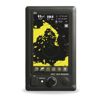
JRC JMA-1030 Series Instruction Manual (198 pages)
MARINE RADAR EQUIPMENT
Brand:
JRC
| Category:
Marine Radar
| Size: 48.37 MB
Table of Contents
Preface
12
Checking the Supplied Items
12
Before Operation
13
Warning Label Mounting Point
19
Equipment Appearance
22
Table of Contents
25
Contents
26
Glossary
31
Chapter 1 INSTALLATION
35
Overview
35
Installation of the Display Unit
36
Selecting the Installation Position
36
Selection of Display Mounting
36
Dimensional Drawing of Display Mounting
37
Examples of Display Mounting
39
Power Cable Installation
44
External Navigational Signal Connection
45
Installation of the Scanner Unit
46
Selecting the Installation Position
46
Lowest Scanner Installation Height
46
Mounting Rack and Mast for the Scanner
47
Scanner and the Surrounding Structural Objects
47
Ensuring View Angle
48
Confirm Mounting Base before Install
50
Connecting the Installation Cable
53
Nke-1066 Scanner (1.5 Feet)
54
Nke-2044 Scanner (2 Feet)
58
Chapter 2 START the BASIC OPERATION
62
Panel and Screen Display Layout
63
Power On/Off
64
Screen Layout
66
Standby Screen
66
Transmission Screen
69
Display the Function Icons
70
Brief Explanation of Icon's Function
74
Setting the Resident Icons
77
Chapter 3 ADJUST the RADAR ECHO
78
Sensitivity Adjustment
79
Sea Clutter Suppression
80
Rain/Snow Clutter Suppression
81
SCREEN BRILLIANCE (Another Operation)
82
Change Range
83
Chapter 4 VRM and EBL FUNCTION
84
Operation of Vrm, Ebl
84
Example of Vrm Function
84
Example of Ebl Function
85
Chapter 5 VARIOUS FUNCTION ICONS
86
Mob Function (man Overboard)
86
Off-Center Function
87
Cursor Function
88
Guard Zone Function
89
Radar Trails
90
Setup the Trail Length
90
SETUP the RADAR TRAILS REF LEVEL, Etc
91
Ais Operations
93
Tt Operations
94
Mode Function
96
Switching Day / Night Mode
97
User Option Key
98
Mark Function
99
Memo
99
Line Function
100
Symbol Marker
102
Radar Echo
103
Pulse Length
104
Ir (Interference Rejection)
104
Target Enhance
105
Process
105
Video Latitude
105
Video Noise Rejection
106
Timed Tx
106
Tuning
107
Motion Mode
108
Vector Length
109
Marker
109
Target
110
Function On/Off
111
Cpa Limit
111
Tcpa Limit
111
Cpa Ring Display
111
Target Number Display
111
Alr Alarm from Ais
111
Ais Display Targets
111
Ais List Display
111
Nmea Info. Set
112
External Monitor Output
113
Chapter 6 OPTION FUNCTIONS
114
Nmea Cable
114
Rectifier Unit
114
Chapter 7 INITIAL SETTINGS
115
Language Selection
116
Tuning Adjustment
116
Bearing Adjustment
117
Range Adjustment
117
Antenna Height Set up
118
Noise Level
118
Communication Port Setup
119
Baud Rate
119
Rx Port
120
Tx Port
120
Tx Data Format
121
Target Information Tx
121
I/F Device
122
Heading Equipment
123
Manual Heading
123
Speed Equipment
123
Manual Speed
123
Magnetic Compass
123
JRC GPS ( for Future Enhancements)
124
Gps Status Display
124
Gps Setting
125
Beacon Setting
129
Sbas Setting
129
Chapter 8 DETAIL PERFORMANCE SETTINGS
130
Sets Radar Echo
130
Main Bang Suppression
131
Target Enhance Level
131
Gain Preset
131
Stc
132
Ftc
132
Radar Alarm Level
133
Tt Function
134
Scanner Function
135
Pulse Repetition Frequency Fine Tuning (Prf Fine Tuning)
135
Stagger Trigger
135
Antenna Rotation Speed
136
Prf Mode
136
Timed Tx
136
Tune Peak Adjustment
137
Tune Indicator Level
137
Control
138
Touch Panel Calibration
138
Buzzer
139
Maintenance Setting
139
Partial Reset
140
All Reset
140
System Time Clear
141
Scanner Time Clear
141
Internal Setting
143
Usb Format
145
System Setting
146
Master/Slave/Demo
146
Own Ship Outline
147
Unit
147
Move Own Ship
148
Use Range Select
148
Display Screen
149
Own Vector Display
149
Standby Display Select
150
Operation Numerical Display
150
Display Color
150
Waypoint Display
150
Ais Filter
151
Error Alarm Mask
151
Scanner
152
Display Unit
152
Rx Data
152
Routine Maintenance
153
Maintenance of each Unit
153
Scanner Nke-1066
153
Scanner Nke-2044
154
Display Ncd-2256
154
Chapter 9 MAINTENANCE and CHECK
155
Performance Check
155
Test Menu
156
System Information
156
System Time
156
Scanner Information
157
Hardware Information
157
Error Log
157
Line Monitor
157
Self Test
157
Replacement of Major Parts
158
Parts Required for Periodic Replacement
159
Fault Finding
159
Alarms and Other Display Lists
159
Trouble Shooting
163
Special Parts
163
Circuit Block to be Repaired
163
Chapter 10 AFTER-SALE SERVICE
164
Keeping Period of Maintenance Parts
164
When You Request for Repair
164
Recommended Maintenance
164
Radar Failure Check List
165
Chapter 11 DISPOSAL
166
Disposal of the Unit
166
Disposal of Used Magnetron
166
China Rohs
166
Chapter 12 SPECIFICATIONS
167
Scanner Dimension
168
Nke-1066
168
Nke-2044
169
Display Dimension
170
Ncd-2256
170
Equipment Outline
172
Configulation
172
Feature
172
Radar Model
172
General Specifications
173
Scanner
174
Scanner (Nke-1066) Specification
174
Scanner (Nke-2044) Specification
175
Display
176
Integrated Display Unit (Ncd-2256)
176
Operational Part
177
Ais Function (Standard Built In)
178
Tt Function (Standard Built In)
178
Input/ Output Signal
178
Input Enable Signal
178
Output Possible Signal
179
Standard Configuration
179
Option Cable
179
Appendix
180
Nke-1066 (1.5Ft) Scanner Interconnection Diagram
180
Nke-2044 (2Ft) Scanner Interconnection Diagram
181
Ncd-2256 Display Unit Inter Connection Diagram
182
Jma-1030 Primary Power Supply Diagram
183
Jma-1030 Interconnection Diagram
184
Operation Sheet
186
Menu Function List
187
Declaration of Conformity
195
Advertisement
Advertisement
Related Products
JRC JMA-1032
JRC JMA-1034
JRC JMA-7725-6
JRC JMA-922B-9XA
JRC JMA-933B-SA
JRC JMA-9132-SA
JRC JMA-7122-6XA
JRC JMA-5322-7HS
JRC JMA-3925-9
JRC JMA-9110-6XAH
JRC Categories
Water Filtration Systems
Marine Radar
Marine Equipment
Radio Parts
Receiver
More JRC Manuals
Login
Sign In
OR
Sign in with Facebook
Sign in with Google
Upload manual
Upload from disk
Upload from URL