Sign In
Upload
Manuals
Brands
JRC Manuals
Compass
Alpatron AlphaMidiCourse
JRC Alpatron AlphaMidiCourse Manuals
Manuals and User Guides for JRC Alpatron AlphaMidiCourse. We have
1
JRC Alpatron AlphaMidiCourse manual available for free PDF download: Installation And Operation Manual
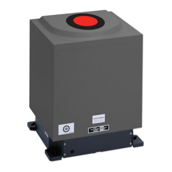
JRC Alpatron AlphaMidiCourse Installation And Operation Manual (82 pages)
Gyro Compass
Brand:
JRC
| Category:
Compass
| Size: 3 MB
Table of Contents
Table of Contents
2
I Preface
5
Revision History
5
Points of Attention
5
Glossary
6
Storage
6
Caution
7
II.1 Warning Label
7
II.2 Location Warning Label
7
II.3 Cautions
7
Introduction
12
III.1 Display and Alarm
12
III.2 Types of Alarm Function
12
III.3 Step Signal Type Repeater Signal Output Function
13
III.4 Serial Signal Type Repeater Signal Output Function
13
III.5 Automatic Speed Error Correction Function
13
III.6 Timer Start
14
III.7 Function of the External Heading Sensor
14
III.8 Warranty Conditions
14
1 Installation Instructions
15
Installation Guidelines
15
General and Specific Tools
15
Unpacking of the Gyro Compass
16
Fitting Master Compass Part 1
17
Fitting Master Compass Part 2
17
Remove Parts from Master Compass Mounting Ring
18
Remove Packing Material from Shock Absorbers
18
Unpacking of Sensitive Element Part 1
19
Unpacking of Sensitive Element Part 2
19
Mounting of Sensitive Element Part 1
20
Mounting of Sensitive Element Part 2
20
Filling with Damping Oil
21
Attach Connector
21
Name and Function of each Unit
22
Configuration
22
Mounting the Master Unit
23
Connecting the Alphamidicourse
24
Alarm List
24
DIP Switch Settings
25
2 Operation
29
Operating Panel
29
Explanation of the Operating Panel
30
Steering Sensor Selection
32
Setting of the Latitude Input
32
Setting of the Ship's Speed Input
32
Setting of the Rate of Turn Filter Constant
33
Data Indications
33
True Heading 1
33
True Heading 2
34
Master Heading
34
Latitude
34
Ship Speed
35
Rate of Turn
35
Alarm Content
36
Start and Stop Sequence
36
Start and Running
38
Start
38
Set Timer Starting Time
39
Set Start Heading
39
Set Latitude Input System
40
Synchronization of the Repeater Compass
41
Settling Time
42
Set Ship Speed Input System
42
Set Rate of Turn Filter Constant
43
Confirmation of True Heading
44
True Heading Indication
45
System Selection
45
Monitoring While Running
45
Confirmation of Alarm Status
46
Confirmation of Gyro Compass True Heading
46
Confirmation of Latitude
46
Confirmation of Ship Speed
46
Operation Procedure of Master Compass Power Switch (Option)
47
Operation Procedure
47
Return Procedure
47
Alarm
47
Alarm Content
48
Corrective Measures GPS Communication Failure
51
Corrective Measures External Heading Sensor Communication Failure
51
Corrective Measures LOG (Serial Signal) Communication Failure
51
Corrective Measures LOG (Contact) Failure
52
Turning the Gyro Compass off
52
3 Specifications
53
4 Maintenance
57
General Procedures
57
Periodical Checks
58
Warning Label Check
58
Spare Parts
58
Disposal Method
59
Troubleshooting
59
General
59
Before Troubleshooting
59
Corrective Measures
60
Corrective Measures When an Alarm Is Activated
60
Failure Phenomena and Corrective Measures
60
Power Supply Failure (Alarm Code 1)
60
Power Supply Failure (Alarm Code 2)
61
Inverter Failure (Alarm Code 3)
61
Rotor Level Failure (Alarm Code 6)
61
Zero Cross Failure (Alarm Code 8)
61
System Communication Failure (1) (Alarm Code A)
62
System Communication Failure (2) (Alarm Code B)
62
GPS Communication Stop (Alarm Code C) or Failure of GPS Data (Alarm Code D)
62
System Internal Communication Failure (1) (Alarm Code E) or System Internal Communication Failure (2) (Alarm Code F)
63
Master Compass Heading Failure (Alarm Code G)
63
External Heading Sensor Communication Stop (Alarm Code L) or External Heading Sensor Data Failure (Alarm Code N)
63
LOG (Serial Signal) Communication Stop (Alarm Code P) or LOG (Serial Signal) Data Failure (Alarm Code U)
63
LOG Contact Failure (Alarm Code U)
63
E5V Failure (Alarm Code R)
63
Gyro Compass Does Not Function, When Power Switch on the Operating Panel Turned on
64
Alarm Is Activated at the same Time When Power Switch Turned on
64
Others
64
When Failures Cannot be Fixed on Board
64
Fuse Replacement
65
Master Compass (Inverter Fuse F1)
66
5 Appendices
67
Drawings
67
Outline Control Unit (One Gyro Compass System)
68
Operating Panel
69
Master Compass
70
Stand Alone Type Control Unit of One Gyro Compass System
72
Connection Diagram
73
Cable Diagram
74
Installation Drawing
75
Terminal Board
76
ITERM Pwb
77
Periodic Check Tables
77
Periodic Check Table 1
78
Periodic Check Table 2
79
Periodic Check Table 3
80
Information to be Supplied to Alphatron Marine
80
Accessories
80
Advertisement
Advertisement
Related Products
JRC Alphatron Marine AlphaTurn
JRC AlphaWind AlphaLine Series
JRC AlphaWind AlphaLine MFM
JRC AlphaWind AlphaLine MFL
JRC ALPHATRON Marine AlphaRiverTrackPilot
JRC Alphatron Marine AlphaScreen19
JRC Alphatron Marine AlphaDynaPos
JRC ALPHATRON Marine Analog Interface Mk.2
JRC Alphatron AlphaPilot MFS
JRC Alphatron Marine AlphaScreen26
JRC Categories
Marine Radar
Water Filtration Systems
Marine Equipment
Receiver
Radio Parts
More JRC Manuals
Login
Sign In
OR
Sign in with Facebook
Sign in with Google
Upload manual
Upload from disk
Upload from URL