Table of Contents
Advertisement
Quick Links
Advertisement
Table of Contents

Related Manuals for JRC Alpatron AlphaMidiCourse

Summary of Contents for JRC Alpatron AlphaMidiCourse
- Page 1 AlphaMidiCourse Gyro Compass Installation and Operation Manual www.jrc.am...
-
Page 2: Table Of Contents
Contents I Preface......................5 I.1 Revision History................................ 5 I.2 Points of Attention..............................5 I.3 Glossary..................................6 I.4 Storage..................................6 II Caution......................7 II.1 Warning Label................................7 II.2 Location Warning Label............................7 II.3 Cautions................................... 7 III Introduction....................12 III.1 Display and Alarm..............................12 III.2 Types of Alarm Function............................12 III.3 Step Signal Type Repeater Signal Output Function.....................13 III.4 Serial Signal Type Repeater Signal Output Function...................13... - Page 3 2.2.3 Setting of the Ship's Speed Input.........................32 2.2.4 Setting of the Rate of Turn Filter Constant....................33 2.3 Data Indications..............................33 2.3.1 True Heading 1............................. 33 2.3.2 True Heading 2............................. 34 2.3.3 Master Heading............................. 34 2.3.4 Latitude................................34 2.3.5 Ship Speed..............................35 2.3.6 Rate of Turn..............................35 2.3.7 Alarm Content...............................
- Page 4 4.6.5.6 System Communication Failure (1) (alarm code A)................62 4.6.5.7 System Communication Failure (2) (alarm code b)................62 4.6.5.8 GPS Communication Stop (alarm code c) or Failure of GPS data (alarm code d)......62 4.6.5.9 System Internal Communication Failure (1) (alarm code E) or System Internal Communication Failure (2) (alarm code F)..........................
-
Page 5: I Preface
I Preface The AlphaMidiCourse Gyro compasses have been designated for any size of vessel to enhance the navigation capabilities and reliability. The gyro compasses eliminate the inconvenience and limitations of magnetic compasses, and provide a variety of electrical outputs to supply accurate and consistent heading information to other navigational equipment. -
Page 6: Glossary
I.3 Glossary The meaning of standard definitions and terms as used in this manual are explained in the table of Definitions Table 1: Table of Definitions on page 6. Definition Explanation External Heading Sensor General term for the Heading Detection Sensor for Magnetic Compass System, Electronic Compass, GPS Compass, etc. -
Page 7: Caution
II Caution To safely install and operate this instrument, so as not to adversely affect the warranty, the WARNINGS and CAUTIONS must be adhered to. II.1 Warning Label The following warning label is attached to this system. II.2 Location Warning Label The warning label is attached to the inside of the door of the Control Panel. - Page 8 • WARNING - Inverter Failure (alarm code 3) • When checking fuses, turn "OFF" the power switch on the operating panel and disconnect the power cable from the ship’s Distribution Terminal Board. • WARNING • When checking fuses, turn "OFF" the power switch, and further disconnect the power cable from the ship’s distribution terminal board.
- Page 9 • CAUTION - Setting Latitude Input • When "GYRO" is selected for the latitude input system, latitude is automatically updated by the ship's speed and the Gyro Compass True Heading. (When the ship's speed input system is "MANUAL", it is not updated automatically.) During navigation, confirm once every two hours that the ship's actual latitude coincides with the indicated latitude.
- Page 10 • Change of the ship's Speed Input System and the Latitude Input System, or large change of the ship's speed and latitude, may cause a large change of the Gyro Compass True Heading. When on automatic steering, first turn the steering mode of the automatic steering system to "MANUAL" to prevent a large course change. Confirm the area around the ship is clear and turn to "AUTO"...
- Page 11 • When an alarm regarding LOG Contact (alarm code "u") is activated and the Gyro Compass' True Heading has not been determined, first turn the steering mode to "MANUAL" or "Non Follow Up", then determine the True Heading because wrong heading information (repeater signal and serial signal) may be sent out. •...
-
Page 12: Introduction
III Introduction This Gyro Compass provides increased Rate of Turn and a broad range of input/output signals. • WARNING - Operations • Improper operations caused by failure of this product, or malfunctions caused by operator's misunderstanding may cause collision or grounding and may result in property damage and environmental pollution. Also, death or serious injury may happen. -
Page 13: Iii.3 Step Signal Type Repeater Signal Output Function
• When an alarm regarding LOG Contact (alarm code "u") is activated and the Gyro Compass' True Heading has not been determined, first turn the steering mode to "MANUAL" or "Non Follow Up", then determine the True Heading because wrong heading information (repeater signal and serial signal) may be sent out. •... -
Page 14: Iii.6 Timer Start
III.6 Timer Start The Gyro Compass can be automatically started according to date and time set for the departure. Note It can be set up to one month maximum. For setting up the departure date and time, operate according to Set Timer Starting Time on page 39 in chapter Operations. -
Page 15: Installation Instructions
1 Installation Instructions This chapter explains the configuration, specifications and structure of this system. 1.1 Installation Guidelines Master Compass 1. Select a mounting location where the deck is horizontal, flat, has little vibration and pitch/roll is as small as possible. Note Mounting location should have sufficient space for installation and servicing. -
Page 16: Unpacking Of The Gyro Compass
Special guide pins are required for installation of the sphere into the phantom ring. Figure 2: Guide Pins for Phantom Ring Installation 1.1.2 Unpacking of the Gyro Compass The three parts: Master Compass, Sensitive Element and Control Panel are supplied in two boxes as shown in pictures labeled 004 to 007. -
Page 17: Fitting Master Compass Part 1
1.1.3 Fitting Master Compass Part 1 Fitting the Master Compass part 1, as shown in pictures labeled 008 to 011. Figure 4: Fitting master Compass Part 1 1.1.4 Fitting Master Compass Part 2 Fitting the Master Compass part 2, as shown in pictures labeled 012 and 013. Figure 5: Fitting Master Compass Part 2 17 | Installation Instructions... -
Page 18: Remove Parts From Master Compass Mounting Ring
1.1.5 Remove Parts from Master Compass Mounting Ring Remove parts from Master Compass mounting ring as shown in pictures labeled 014 to 018. Figure 6: Remove parts 1.1.6 Remove Packing Material from Shock Absorbers Remove packing material from shock absorbers as shown in pictures labeled 019 to 021. Figure 7: Remove Packing Material Shock Absorbers 18 | Installation Instructions... -
Page 19: Unpacking Of Sensitive Element Part 1
1.1.7 Unpacking of Sensitive Element Part 1 Unpack Sensitive Element as shown in pictures labeled 022 to 025. Figure 8: Unpacking Sensitive element part 1 Note Handle with care and keep packaging material for reuse when returning for servicing. 1.1.8 Unpacking of Sensitive Element part 2 Unpack Sensitive Element as shown in pictures labeled 026 and 027 Figure 9: Unpacking Sensitive Element part 2 Note Handle Sensitive Element with great care. -
Page 20: Mounting Of Sensitive Element Part 1
1.1.9 Mounting of Sensitive Element Part 1 Mount the Sensitive Element as shown in pictures labeled 028 to 031. Figure 10: Mounting of Sensitive Element part 1 1.1.10 Mounting of Sensitive Element Part 2 Mount the Sensitive Element as shown in pictures labeled 032 to 034. Figure 11: Mounting of Sensitive Element part 2 20 | Installation Instructions... -
Page 21: Filling With Damping Oil
1.1.11 Filling with Damping Oil Fill up container with Damping Oil as shown in pictures labeled 037 to 039. Figure 12: Filling with Damping Oil 1.1.12 Attach Connector Attach Connector and fix securely to Sensitive Element as shown in pictures below. Figure 13: Attach Connector 21 | Installation Instructions... -
Page 22: Name And Function Of Each Unit
1.2 Name and Function of Each Unit Names and functions of each unit. Name Function Master compass The sensitive element is built-in. It is a unit to detect the ship's heading. Control Unit This unit has various indicators for True Heading, Latitude, Rate of Turn, Ship Speed and Alarms, and the operating switches. -
Page 23: Mounting The Master Unit
1.4 Mounting the Master Unit Mounting of the master compass unit is as shown in Figure 15: Mounting position on page 23. Figure 15: Mounting position Figure 16: Inverter Unit Location 1. Orientate the Inverter Unit at the back of the Master Compass to the Stern of the ship. Note Install the Gyro Compass with in 5˚... -
Page 24: Connecting The Alphamidicourse
1.5 Connecting the AlphaMidiCourse Refer Connection Diagram and Cable Diagram for cable connections Figure 46: Connection Diagram on page 73, Figure 47: Cable Diagram on page 74. 1. Connect power and signaling cables as indicated in the connection diagram. 2. Use wire straps to fasten cables. CABLE SPECIFICATIONS - See Connection Diagram and Cable Diagram Figure 46: Connection Diagram on page 73, Figure 47: Cable Diagram on page 74. -
Page 25: Dip Switch Settings
1.7 DIP Switch Settings The AlphaMidiCourse Gyro Systems include several Dip Switch Settings. Figure 17: DIP Switch Settings With the exception of the two switches on the ICIF board in the Control Unit, no switches require to be set when installing the system. - Page 26 Standard Details Function Read Remarks Setting Timing NO.7 [OFF] Master Compass [ON] : Master Compass is installed Start Up reversely 180˚ Installation NO.8 [OFF] Do Not Touch Table 4: MCC pwb switch assign * For MCC pwb check mode : S1 all [ON]. Interval Setting NMEA: 100msec, or 200msec, or 1sec.¹...
- Page 27 ICIF Standard Details Function Read Remarks pwb S2 Setting Timing NO.5 [OFF] NO5.[OFF] NO6. NO5.[ON] NO6. Start Up Serial Signal [OFF] ; 1sec [OFF] ; 200msec Transmit NO.6 [OFF] NO5.[OFF] NO6. NO5.[ON] NO6. Frequency [ON] ; 100msec [ON] ; Invalid IEC61162-1 ed.2 (1sec) NO.7...
- Page 28 IOPT Standard Details Function Read Remarks Setting Tuning NO.5 [OFF] HDT / THS [OFF] : HDT [ON] : THS Start Up sentence NO.6 [OFF] Do Not Touch * For SCC pwb check mode : S1, S2, S3 all [ON] * For ICIF pwb check mode : S1, S2 all [ON] S3 (except No.8 all [ON] 28 | Installation Instructions...
-
Page 29: Operation
2 Operation In this chapter, procedure of operation, starting and stopping of this system are explained. Before operation, confirm that each unit of the master compass and the control unit are properly installed. • WARNING • Matters requiring attention in starting up and operations during progress are described in chapter Operations and are punctuated with a CAUTION or a WARNING, which must be strictly observed. -
Page 30: Explanation Of The Operating Panel
2.2 Explanation of the Operating Panel Figure 19: Operating Panel POWER switch Power switch / Power indicator 1. Open cover 2. Press to start/stop system 3. Close cover after start-up, so as not to inadvertently push the button. DISP switch Select the displayed item and the displayed data. - Page 31 GYRO switch System selection switch (Gyro). 1. Press to select required system. 2. "GYRO" system is select. 3. For system selection, refer to System Selection on page 45 EXT switch System selection switch (External). 1. Press to select required system. 2.
-
Page 32: Steering Sensor Selection
True Bearing 2: *** ESt = External Sensor true bearing ***.* GYt = Gyro-compass true bearing ESt or GYt Master Compass Bearing: C.P.S. = Compass ***.* C.P.S Latitude: ***.* LA.n = Latitude North ***.* LA.S = Latitude South LA.n or LA.S Ship's speed: ***.* G.Sd = Gps.Speed ***.*... -
Page 33: Setting Of The Rate Of Turn Filter Constant
2.2.4 Setting of the Rate of Turn Filter Constant 1. Press the SET button when the Rate of Turn Filter Constant is changed. 2. Press ▼or▲ to select the Filter Constant. Note The Filter Constant can be set to 0.5, 1 or 2 through to 10 in 2second steps. 3. -
Page 34: True Heading 2
2.3.2 True Heading 2 If the True Heading of the sensor is not selected as system, either the Gyro Compass true heading or the external heading sensor True Heading, is displayed. System Heading Data Mode Indicator Selection Indicator Gyro 123.4 345.6 External 345.6... -
Page 35: Ship Speed
2.3.5 Ship Speed Current Ship Speed is displayed. See example: Present Speed input system is "GPS". Note When a GPS communication failure is generated, the data indicator starts blinking. Note When a LOG (contact) failure is generated, the data indicator starts blinking. Note When a LOG (serial) failure is generated, the data indicator starts blinking. -
Page 36: Alarm Content
2.3.7 Alarm Content An alarm activated in the Gyro Compass is displayed by an alarm code. For the alarm code indication, refer to Alarm on page 47. When there are no alarms, the display indication is as shown: When an alarm is activated the display indication is as shown. Alarms are displayed in the data indicator in the activated order from the left as shown below. - Page 37 2. Setting (after start-up) • Latitude setting: Confirm the latitude indication and set again if necessary. • Speed setting: Confirm the speed indication and set again if necessary. • Repeater synchronization: Synchronize each repeater. 3. Setting (Just before departure, or 6 hours or more after starting) •...
-
Page 38: Start And Running
System selection (switching) may cause large change of the True Heading. 1. During automatic steering, first turn the steering mode of the automatic steering system to "MANUAL" to prevent large change of course. 2. Confirm surrounding area of ship is clear and turn to "AUTO" steering again. •... -
Page 39: Set Timer Starting Time
2.5.2 Set Timer Starting Time After turning ON the power and the software version number indicates FINISHED, the display automatically shows current date and time¹. Note ¹ In cases where this function is not included, after indicating software version, it will display START HEADING. -
Page 40: Set Latitude Input System
Figure 26: Start Heading Set Start Heading: 1. Press switch ▲, or ▼. 2. Press switch ACK/ENT to confirm. The display indicates the Gyro Compass True Heading and the Master Compass turns to the entered heading. Note When the system starts from the heading when the last azimuth operation was completed, setting of the "start heading"... -
Page 41: Synchronization Of The Repeater Compass
Figure 28: Set Latitude Input 4. Press ACK/ENT switch to confirm. 5. Press switch ▲, or ▼, when GYRO is selected, to select the latitude. 6. Press ACK/ENT switch to confirm. The calculated latitude by ship's speed and True Heading is indicated. 2.5.5 Synchronization of the Repeater Compass Synchronization of the Repeater Compass¹. -
Page 42: Settling Time
2.5.6 Settling Time The time to "SETTLE" takes approx. 3 hours maximum depending on the starting condition. 2.5.7 Set Ship Speed Input System • CAUTION - Setting Speed Input • Change of the ship's input system or large change of ship's speed may cause large change of the True Heading. -
Page 43: Set Rate Of Turn Filter Constant
Figure 31: MANUAL Input System Figure 32: GPS Input System Figure 33: LOG (contact signal) Input System Figure 34: LOG (serial signal) Input System 4. Press ACK/ENT switch to confirm. When "MANUAL" was selected, the ship's speed is displayed in the indicator. 5. -
Page 44: Confirmation Of True Heading
Figure 35: Rate of Turn filter constant 2. Press SET switch When Rate of Turn Filter Constant has changed. INFO: Figure 36: Changed Rate of Turn filter constant 3. Press switch ▲, or ▼ to select the "Filter Constant". Note The “Filter Constant” can be set to 0.5, 1 or 2 through to 10 in 2 seconds intervals. 4. -
Page 45: True Heading Indication
Figure 37: Confirmation True Heading Note The offset displayed is cleared when the system is turned off, or when the master compass has passed through the reference angle of the master compass heading. 4. Press ACK/ENT switch to confirm. 2.5.10 True Heading Indication When all settings have been completed, press DISP switch to display the True Heading in the indicators. -
Page 46: Confirmation Of Alarm Status
Perform monitoring while running as follows: 2.7.1 Confirmation of Alarm Status 1. Confirm that the alarm indicator lamp on the operation panel is off. Note When a failure is activated in the system, the alarm indicator blinks and buzzes. 2. Confirm the alarm code displayed in the indicator. 3. -
Page 47: Operation Procedure Of Master Compass Power Switch (Option)
2.8 Operation Procedure of Master Compass Power Switch (Option) • CAUTION - System Selection • System selection (switching) may cause large change of True Heading. When on automatic steering, first turn the steering mode of the automatic steering system to "MANUAL" to prevent a large course change. Confirm the area around the ship is clear and turn to "AUTO"... -
Page 48: Alarm Content
Note If the alarm occurs only momentarily, the alarm indicator extinguishes by pressing the ACK/ENT switch. Note When the alarm indicator did not extinguish by pressing the ACK/ENT switch, the alarm conditions continues. 2. Take appropriate actions referring to Troubleshooting on page 59, when the alarm conditions continue and confirm the alarm code. - Page 49 Is activated when a failure is generated in the communication from the control unit to the master compass. 8. GPS communication break. Is activated when the serial signal from GPS stops, or GPS operation stops. When this alarm is activated, operate according to Corrective Measures GPS Communication Failure on page 51.
- Page 50 Is activated when the serial signal from the external heading sensor has stopped or the external heading sensor has stopped operating. 14. External heading sensor data failure. Is activated when a failure is generated in the serial signal from the external heading sensor. Note When this alarm is activated, operate according to Corrective Measures External Heading Sensor Communication Failure on page 51.
-
Page 51: Corrective Measures Gps Communication Failure
2.9.2 Corrective Measures GPS Communication Failure • CAUTION - Corrective Measures GPS Communication Failure • When an alarm related to GPS (alarm code "c" or "d") is activated and the Gyro Compass' True Heading has not been determined, first turn the steering mode to "MANUAL", or "Non Follow Up", then determine the True Heading, because wrong heading information (repeater signal and serial signal) may be sent out. -
Page 52: Corrective Measures Log (Contact) Failure
The Gyro Compass True Heading and the heading information sent out, which are currently displayed, is the corrected value based on the ship's speed immediately before the alarm was activated. 1. Select other mode than "LOG (serial signal)" for the ship's speed input system. See Set Ship Speed Input System on page 42 2. -
Page 53: Specifications
3 Specifications Refer to the As Built plan kept aboard and table below. Model Description AlphaMidiCourse Display Digital with 7 digits Performance Settle point error < 0.3° Settle point repeatability < 0.2° Static accuracy < 0.3° Dynamic accuracy < 0,5° Follow-up speed max. - Page 54 Name Type Mass Finish Remarks Dwg. (kg) GYRO COMPASS Alpha- GENERAL MidiCourse INPUT SIGNAL INPUT SIGNAL SENTENCE OUTPUT SIGNAL OUTPUT SIGNAL SENTENCE INSTALLATION NOTES Alpha- MidiCourse ENTER UNIT Alpha- WIRING DIAGRAMS MidiCourse EXTERNAL FORM MASTER COMPASS Alpha- RAL - MidiCourse 7012 Basalt grey...
- Page 55 BAUD RATE 4800 bps DATA BITS 8 bits PARITY none STOP BITS TRANSMIT FREQ. Table 13: Type of Protocol DATA NO.1 $-GGA,x,xx,x,N,xx.x,E,x,∼*hh<CR><LF> ↑LAT.: ↑GPSQI:GPS $-GLL,xxxx.xx,N,xxxx.xx,E∼*hh<CR><LF> ↑LAT.: Note GGA sentence is high priority. DATA NO.2 $-VTG,xx,T,xx,M,xx.x,N,xx,K*hh<CR><LF> ↑SPEED (knots) SPEED LOG DATA NO.1 $-VBW.x.x.x.x.A.x.x.x.x.A∼*hh<CR><LF>...
- Page 56 *¹: Refer to type of Protocol. *²: Type of Protocol can be selected for each circuit. (Refer to wiring diagram regarding number of circuits). BAUD RATE 4800 bps 38400 bps DATA BITS 8 bits 8 bits PARITY none none STOP BITS TRANSMIT FREQ.
-
Page 57: Maintenance
4 Maintenance • WARNING - Maintenance • During maintenance or check of the product, touching internal parts may cause electric shock, because the ship's power supply is still connected to the system distribution board, even if the main power switch of this product is turned "OFF". -
Page 58: Periodical Checks
Note The trouble shooting and repair should be carried out by the engineer according to the results of the checks of the faulty items. 4.2 Periodical Checks Use the periodical check table for the periodical check. See Periodic Check Table 1 on page 78 Frequency of the checks are: 1. -
Page 59: Disposal Method
Part Name Part No. Belt 3107.9160 HRZC PWB 3107.9162 Inverter PWB 3107.9164 Slip Ring 3107.9166 Flexibel Wire (east) 3107.9168 Gpower PWB 3107.9170 Table 17: Spare Parts List 4.5 Disposal Method When disposing of this system, it should be treated as industrial waste and disposed of in accordance with the laws and regulations. -
Page 60: Corrective Measures
2. Tools (instruments) required for checking: • Minus head screw driver and general tools • Circuit tester 4.6.3 Corrective Measures Measures can be taken to rectify some failures. • CAUTION - Corrective Measures • Before checking and replacing of fuses, and disconnecting / connecting of each unit, connector, printed circuit, terminal cable, turn "OFF"... -
Page 61: Power Supply Failure (Alarm Code 2)
INFO: Stand alone type (Model - I) Voltage The system where both the master compass and the control unit are not built into the automatic steering system. Input terminals of the emergency power supply (between 1B+ and 24 V DC, within -20 % to +30 % 1B- of the external terminal board TB3-5 and TB3-6. -
Page 62: System Communication Failure (1) (Alarm Code A)
Note Data Display will be blinking. 2. Press ACK/ENT switch to determine the Gyro Compass True Heading. Note Set True Heading again according to Confirmation of True Heading on page 44, if the determined True Heading has an error. 3. Contact Alphatron Marine, or agent, even when True Heading has been recovered. 4.6.5.6 System Communication Failure (1) (alarm code A) 1. -
Page 63: System Internal Communication Failure (1) (Alarm Code E) Or System Internal Communication Failure (2) (Alarm Code F)
4.6.5.9 System Internal Communication Failure (1) (alarm code E) or System Internal Communication Failure (2) (alarm code F) 1. Confirm that the external heading sensor signal processing unit of this system operates properly. 2. Contact Alphatron Service Engineer, or agent, after checking step 1. 4.6.5.10 Master Compass Heading Failure (alarm code G) •... -
Page 64: Gyro Compass Does Not Function, When Power Switch On The Operating Panel Turned On
Note Refer to the As Built plan kept on board of the ship for the connected equipment. 2. Operate it according to the particular Operator Manual of the equipment, when a failure has been activated. 3. Contact Alphatron Marine Service Engineer, or agent, after checking steps 1 and 2. 4.6.5.15 Gyro Compass does not Function, when Power Switch on the Operating Panel turned ON. -
Page 65: Fuse Replacement
4.6.6 Fuse Replacement To replace a fuse when it has blown: Figure 39: Fuses Control Unit 1. Turn OFF the power switch on the operating panel. 2. Disconnect the power supply from the ship’s distribution board and the emergency power supply of this system. 3. -
Page 66: Master Compass (Inverter Fuse F1)
4.6.6.1 Master Compass (Inverter fuse F1) Fuse F1 is located inside the fuse holder in the front and is ∅6.35x31,8mm . All other fuses are ∅5.2x20mm. Figure 40: Master Compass Inverter Unit 1. Press and turn the fuse holder edge counterclockwise with a screw driver to open the fuse holder. 2. -
Page 67: Appendices
5 Appendices The Appendix contains Drawings and Periodic Check Tables. 5.1 Drawings Drawing Contents: 1. Outline Control Unit (One Gyro Compass System). 2. Operating Panel. 3. Master Compass. 4. Stand alone type Control Unit of One Gyro Compass System. 5. Connection Diagram. 6. -
Page 68: Outline Control Unit (One Gyro Compass System)
5.1.1 Outline Control Unit (One Gyro Compass System) Figure 41: Control Box 68 | Appendices... -
Page 69: Operating Panel
5.1.2 Operating Panel Figure 42: Operating Panel 69 | Appendices... -
Page 70: Master Compass
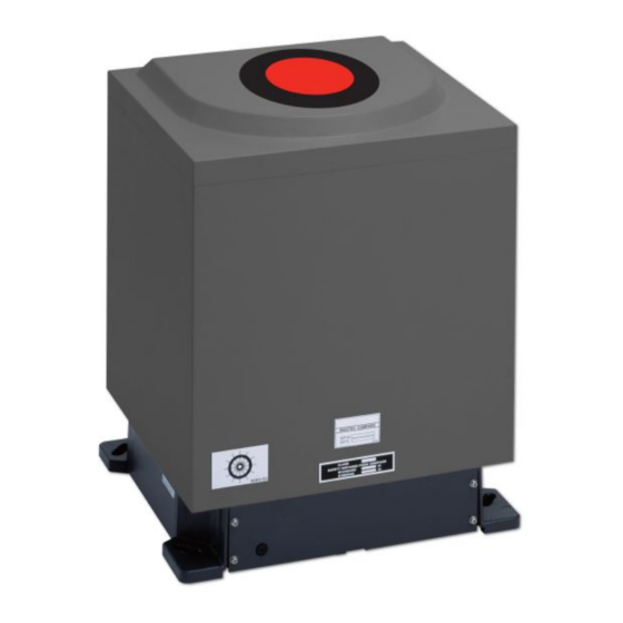
5.1.3 Master Compass Figure 43: Main Unit 70 | Appendices... - Page 71 Figure 44: Open Gyro Compass 71 | Appendices...
-
Page 72: Stand Alone Type Control Unit Of One Gyro Compass System
5.1.4 Stand Alone Type Control Unit of One Gyro Compass System Figure 45: Stand alone type Control Unit of One Gyro Compass System 72 | Appendices... -
Page 73: Connection Diagram
5.1.5 Connection Diagram Figure 46: Connection Diagram 73 | Appendices... -
Page 74: Cable Diagram
5.1.6 Cable Diagram Figure 47: Cable Diagram 74 | Appendices... -
Page 75: Installation Drawing
5.1.7 Installation Drawing Figure 48: Installation Drawing 75 | Appendices... -
Page 76: Terminal Board
5.1.8 Terminal Board Figure 49: Terminal Board 76 | Appendices... -
Page 77: Iterm Pwb
5.1.9 ITERM pwb Figure 50: ITERM pwb 5.2 Periodic Check Tables Periodic Check Table Contents: 1. Periodic Check Table 1. 2. Periodic Check Table 2. 3. Periodic Check Table 3. 77 | Appendices... -
Page 78: Periodic Check Table 1
5.2.1 Periodic Check Table 1 Check mark ○ : Normal, △ : Normal after rework or repair (Example of filling up) Date checked Installation completed '02.06.14 Inspector service engineer name ○○○○ Check items a. Confirm that the value of each repeater synchronizes with the ○... -
Page 79: Periodic Check Table 2
5.2.2 Periodic Check Table 2 Check mark ○ : Normal, △ : Normal after rework or repair (example filling in) Date checked Installation completed on '02.06.14 Inspector service engineer name ○○○○ Check items a. Confirm tightness of fixing screws in mechanical sections and ○... -
Page 80: Periodic Check Table 3
5.2.3 Periodic Check Table 3 Perform maintenance and check once a year. Part Name Part No. Interval Sensitive Element 3107.9152 2 - 3 Brush 3107.9154 Step Motor 3107.9158 Belt 3107.9160 HRZC PWB 3107.9162 Inverter PCB 3107.9164 Gpower PWB 3107.9170 Flexible wire (EAST) 3107.9168 Slop Ring 3107.9166... - Page 81 Repeater The repeater compass receives the ship’s heading Compass bearing signal transmitted from the master compass and remotely indicates the bearing. The repeater (weight: 5 kg) has an analogue display for the indication of the heading display. The case is made of GRP (Glass fiber Reinforced Plastic, thus corrosion free) and has a waterproof construction, able to use on open deck.
- Page 82 All over the world, close to the customer JRC/Alphatron Marine B.V. Schaardijk 23 (harbor 115) The information in this document is subject to change without notice and 3063 NH Rotterdam does not represent a commitment on the part of Alphatron Marine B.V.