Sign In
Upload
Manuals
Brands
Johnson Controls Manuals
Water Dispenser
LSWF
Johnson Controls LSWF Manuals
Manuals and User Guides for Johnson Controls LSWF. We have
3
Johnson Controls LSWF manuals available for free PDF download: Manual, Startup Manual, Reassembly
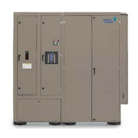
Johnson Controls LSWF Manual (210 pages)
WITH IPU2 CONTROL 25–105 TON
Brand:
Johnson Controls
| Category:
Chiller
| Size: 15.4 MB
Table of Contents
General Safety Guidelines
2
Changeability of this Document
3
Change Bars
3
Associated Literature
3
Nomenclature
4
Table of Contents
5
Section 1 - Introduction
10
About this Manual
10
Description of Unit
10
TABLE 1 - Acronym Chart
10
Section 2 - Installation
11
Approvals
11
Limitations
11
Unit Inspection
11
TABLE 2 - Voltage Limitations
11
TABLE 3 - Operating Limitations
11
TABLE 4 - LSWU/LSWD/LSWF Minimum CFM
11
Location and Clearances
12
FIGURE 1 - Caution Label
12
FIGURE 2 - Recommended Service and Maintenance Clearance, Top Discharge (LSW_025-040)
12
FIGURE 3 - Recommended Service and Maintenance Clearance, Top Discharge(LSW_050-060)
13
FIGURE 4 - Recommended Service and Maintenance Clearance, Top Discharge (LSW_070-105)
14
FIGURE 5 - Recommended Service and Maintenance Clearance with Sound Attenuating Plenum
15
FIGURE 6 - Recommended Service and Maintenance Clearance with Sound Attenuating Plenum
16
FIGURE 7 - Recommended Service and Maintenance Clearance with Airside Economizer (LSW_025-040)
17
FIGURE 8 - Recommended Service and Maintenance Clearance, Front Discharge (LSW_070-105)
18
FIGURE 9 - Recommended Service and Maintenance Clearance with Sound Attenuating Plenum
19
FIGURE 10 - Recommended Service and Maintenance Clearance with Airside Economizer (LSW_050-060)
20
FIGURE 11 - Recommended Service and Maintenance Clearance with Airside Economizer (LSW_070-105)
21
Rigging and Unit Handling
22
FIGURE 12 - Vibration Isolation Pad Locations (LSW_025-040)
23
FIGURE 13 - Vibration Isolation Pad Locations (LSW_050-060)
24
FIGURE 14 - Vibration Isolation Pad Locations (LSW_070-105)
25
FIGURE 15 - Warning Label
26
FIGURE 16 - Lifting Recommendations, Coil Section Only (LSW_025-040)
27
FIGURE 17 - Lifting Recommendations, Coil Section Only (LSW_050-060)
28
FIGURE 18 - Lifting Recommendations, Coil Section Only (LSW_070-105)
29
FIGURE 19 - Lifting Recommendations, Fan Section Only (LSW_025-040)
30
FIGURE 20 - Lifting Recommendations, Fan Section Only (LSW_050-060)
31
FIGURE 21 - Lifting Recommendations, Fan Section Only (LSW_070-105)
32
FIGURE 22 - Lifting Recommendations, Fan and Coil Section Combined (LSW_025-040)
33
FIGURE 23 - Lifting Recommendations, Fan and Coil Section Combined (LSW_050-060)
34
FIGURE 24 - Lifting Recommendations, Fan and Coil Section Combined (LSW_070-105)
35
TABLE 5 - Operating Weights (LSW_025-060)
36
TABLE 6 - Supply Fan Motor Weights
36
Factory-Supplied Plenum
37
TABLE 7 - Supply Fan Variable Frequency Drive Weights
37
TABLE 8 - Operating Weights (LSW_070-LSW_105)
38
Segmented Unit Assembly
39
Remove Shipping Restraints
39
FIGURE 25 - Shipping Restraint Locations
39
Physical Data
40
TABLE 9 - Water-Cooled Self-Contained Unit Data (LSW_025-060)
41
TABLE 10 - Water-Cooled Self-Contained Unit Data (LSW_070-105)
41
TABLE 11 - Electric Heat for LSW_025-060
43
Dimensions
45
FIGURE 26 - Unit Dimensions, Top Discharge Assembled (LSWU 025-040)
45
FIGURE 27 - Unit Dimensions, Top Discharge, Assembled (LSWU 050-060)
46
FIGURE 28 - Unit Dimensions, Top Discharge, Assembled (LSWU 070-105)
47
FIGURE 29 - Unit Dimensions, Front Discharge, Assembled (LSWF 050-060)
48
FIGURE 30 - Unit Dimensions, Top Discharge, Segmented (LSWU_025-040)
49
FIGURE 31 - Unit Dimensions, Top Discharge, Segmented (LSWU 050-060)
50
FIGURE 32 - Unit Dimensions, Top Discharge, Segmented (LSWU 070-105)
51
FIGURE 33 - Unit Dimensions, Front Discharge, Segmented (LSW_050-060)
52
FIGURE 34 - Unit Dimensions, Front Discharge, Assembled (LSW_025-040)
53
FIGURE 35 - Unit Dimensions, Front Discharge, Segmented (LSW_025-040)
54
FIGURE 36 - Unit Dimensions, down Flow, Assembled (LSW_050-060)
55
FIGURE 37 - Unit Dimensions, down Flow, Segmented (LSW_050-060)
56
FIGURE 38 - Bypass Plenum for down Flow, Segmented (LSW_050-060)
57
FIGURE 39 - Unit Dimensions, down Flow, Assembled (LSW_050-060)
58
FIGURE 40 - Unit Dimensions, down Flow, Segemented (LSW_025-040)
59
FIGURE 41 - Bypass Plenum for down Flow, Segemented (LSW_025-040)
60
FIGURE 42 - Unit Dimensions Front Discharge, Assembled (LSWF 070-105)
61
FIGURE 43 - Unit Dimensions, Front Discharge, Segmented (LSWF 070-105)
62
FIGURE 44 - Half Outlet Plenum Option (LSWU 025-040)
63
FIGURE 45 - Half Outlet Plenum Option (LSWU 050-060)
64
FIGURE 46 - Full Outlet Plenum Option (LSWU 025-040)
65
FIGURE 47 - Full Outlet Plenum Option (LSWU 050-060)
66
FIGURE 48 - Unit Dimensions, Discharge Plenum (LSWU 070-105)
67
FIGURE 49 - Unit Dimensions Sound Attenuating Plenum Option (LSWU/F 025-040)
68
FIGURE 50 - Unit Dimensions Sound Attenuating Plenum Option (LSWU/F 050-060)
69
FIGURE 51 - Unit Dimensions All Models, Inlet Plenum (LSWU/F 070-105)
70
FIGURE 52 - Unit Dimensions Airside Economizer Option (LSW_025-040)
71
FIGURE 53 - Unit Dimensions Airside Economizer Option (LSW_050-060)
72
FIGURE 54 - Unit Dimensions Airside Economizer Option (LSW_070-105)
73
Electrical Data
74
Field Wiring
75
Bacnet Communication
75
Pump Start Output
76
Alarm Contacts
76
Isolation Damper Control
76
CTB1 Field Control Wiring (Inputs)
76
FIGURE 55 - CTB1 Field Control Wiring
77
Phase Monitor
78
Ducting
78
Water Piping
78
FIGURE 56 - Condenser Connections
79
Static Pressure Transducer Installation (VAV Units Only)
81
FIGURE 57 - Condenser Trap
81
Static Pressure Transducer Installation (Flexsys ™ Units Only)
82
FIGURE 59 - Duct Static Transducer Locations
82
FIGURE 58 - Duct Static Transducer Location
82
Duct High Pressure Safety Switch
83
Dirty Filter Switch
83
Static Pressure Transducer Installation (Flexsys ™ Units Only)
83
Return, Outdoor, Supply Air, and Mixed Air Sensors
84
Steam Heat
84
Hot Water Heat
85
Electric Heat
85
Filters
85
Section 3 - Start-Up
87
Crankcase Heaters
87
Pre-Startup Requirements
87
Unit Checks - Power Applied
88
Initial Start-Up
88
TABLE 12 - Setscrew Torques
88
TABLE 13 - R410-A Pressure / Temperature Chart
90
Section 4 - Maintenance
91
General
91
Periodic Maintenance - Monthly
91
TABLE 14 - Fan Bearing - Lubrication Intervals
91
Periodic Maintenance - Three to Six Months
92
Periodic Maintenance - Yearly
92
TABLE 15 - Belt Tension Data
92
FIGURE 60 - Sheave Alignment
93
FIGURE 61 - Belt Tensioning Gauge
93
Water Pressure Drop Tables
96
TABLE 16 - Condenser Water Pressure Drop (LSW_025-040), Feet of W.C
96
TABLE 17 - Condenser Water Pressure Drop (LSW_050-060), Feet of W.C
97
TABLE 18 - Condenser Water Pressure Drop (LSW_070-105), Feet of W.C
97
TABLE 35 - Condenser
97
Determining Water Flow (Condenser Only)
98
Determining Water Flow (Waterside Economizer Active)
98
Section 5 - Sequence of Operation
99
Unit Type
99
Constant Volume (CV) Mode Operation
99
FIGURE 62 - Constant Volume Setpoint Determination
101
TABLE 19 - Active SAT Setpoint Determination, Zone Temperature
102
Variable Air Volume (VAV) Mode Operation
103
FIGURE 63 - Active DSP Setpoint Vs. Duct Static Pres RST Voltage
104
FIGURE 64 - Supply Fan VFD Frequency
105
TABLE 20 - Piezometer Airflow Measurements
106
FIGURE 65 - Active SAT Setpoint Vs. Supply Air Temp RST Voltage
110
FIGURE 66 - Active SAT Setpoint Vs. Outside Air Temp
110
FIGURE 67 - Active SAT Setpoint Vs. Supply Fan Speed
110
Compressor Control and Sequencing
111
FIGURE 68 - Active SAT Setpoint Vs. Return Air Temp
111
TABLE 21 - System a Compressor Capacity (25-60 Ton)
111
FIGURE 69 - System a Compressor at 1/3 Capacity
112
FIGURE 70 - System a Compressor at 2/3 Capacity
112
FIGURE 71 - System a Compressor at Full Capacity
112
Compressor Operation
114
TABLE 22 - Compressor Status Priority Level
115
TABLE 23 - Compressor Safeties
116
Water Cooled Condenser Operations
119
FIGURE 72 - Condenser Only Piping Diagram with no Valves from the Factory
119
FIGURE 73 - Condenser and Piping Diagram W/ Condenser Only Valve from the Factory
120
FIGURE 74 - Cond Water Valve Vs. Condenser Pressure PI Output
121
FIGURE 75 - Condenser Operation and Piping Diagram W/ Condenser and Bypass Valves
121
FIGURE 76 - Bypass Valve Position Vs. Cond Water Valve Position
122
Waterside or Air Economizer Operation
123
FIGURE 77 - Condenser and Water Economizer Valve Operation and Piping Diagram
123
FIGURE 78 - Waterside Economizer Actions
124
Heat Operations
134
Table 24 - Cfm
134
TABLE 25 - Heat Stages
134
Ventilation System
137
Dirty Filter Switch
138
Flexsys Operation
138
TABLE 26 - Supply Air Density from Temperature and Altitude
142
Section 6 - User Interface Control Center
143
User Interface Control Center
143
FIGURE 79 - User Interface Control Panel
143
TABLE 27 - Status
145
TABLE 28 - Unit Data
146
TABLE 29 - Cooling
147
TABLE 30 - Compressor Systems (A-F)
148
TABLE 31 - Supply System
149
TABLE 32 - Heating
150
TABLE 33 - Economizer
151
TABLE 34 - Ventilation
152
Setpoints
153
TABLE 36 - Setpoints
153
Program
155
TABLE 37 - Program
155
Options
157
TABLE 38 - Options
157
Date / Time
158
Schedule
158
Operating Hours / Start Counter
159
TABLE 39 - Operating Hours / Start Counter
159
Printer
160
Service
161
TABLE 40 - Service
161
History
167
TABLE 41 - History Key Sequence
167
Password
168
Power up Banner
169
Communication
169
FIGURE 80 - IPU Control Board
170
FIGURE 81 - MAC Address Switches
171
Table 42 - Bacnet Ms/Tp, Modbus, Bacnet Ip
172
Section 7 - Parameter Descriptions and Options
183
TABLE 43 - Definitions
183
Section 8 - Service
195
Analog Input Operation
195
TABLE 44 - Temperature Sensor Resistance
196
TABLE 45 - Duct Pressure Transducer
196
TABLE 46 - Pressure Transducers
196
TABLE 47 - Humidity Sensor Outputs
197
TABLE 48 - Discharge Thermistor Temperature / Resistance
197
Digital Compressor Controller Fault Codes
198
Faults
199
FIGURE 82 - Control Board I/O Locations
201
TABLE 49 - Control Board I/O Locations
202
TABLE 50 - Warning Description Table
205
TABLE 51 - Fault Auto - Reset
206
TABLE 52 - Faults Lockout
207
Multi Media Card
208
TABLE 53 - Data Log Error State
209
TABLE 54 - Data Log Error Log Detail
209
Advertisement
Johnson Controls LSWF Reassembly (24 pages)
SPLIT SHIPMENT FIELD REASSEMBLY WATER-COOLED SELF-CONTAINED UNITS WITH IPU2 CONTROL 25–105 TON
Brand:
Johnson Controls
| Category:
Storage
| Size: 1.1 MB
Table of Contents
Table of Contents
5
Section 1 - Small Cabinet Field Assembly
7
Introduction
7
Parts
7
Small Cabinet
7
FIGURE 1 - Small Cabinet: Models 025, 032, 035, and 040
7
TABLE 1 - Small Cabinet Fan Compartment Parts List
7
FIGURE 2 - View of Gasket Material Applied Around Supply Fan Opening
8
FIGURE 3 - Coil Section, Isometric View
8
FIGURE 4 - Coil Section, Side View
8
Reassembly Procedure
8
TABLE 2 - Small Cabinet Filter Section Parts List
8
FIGURE 5 - Tuck Wiring Inside Coil Section
9
FIGURE 6 - Align Rectangular Openings on Coil and Fan Sections
9
FIGURE 7 - Fan Section Sockets
9
FIGURE 8 - Align Top Panels
9
FIGURE 10 - Open Pressure Seal Door
10
FIGURE 11 - Remove Compressor Access Panel
10
FIGURE 12 - Enter the Reconnect Area
10
FIGURE 9 - Align Bases
10
FIGURE 13 - Location of Nut Inserts in Fan Section
11
FIGURE 14 - Install Screws Around Fan Opening
11
FIGURE 15 - Filter Rack
12
FIGURE 16 - Filter Rack Attachment
12
Section 2 - Medium Cabinet Field Reassembly
13
Introduction
13
Parts
13
FIGURE 17 - Medium Cabinet: Models 050 and 060
13
TABLE 3 - Medium Cabinet Fan Compartment Parts List
13
Reassembly Procedure
14
FIGURE 18 - View of Gasket Material Applied Around Supply Fan Opening
14
Medium Cabinet
14
FIGURE 19 - Coil Section
14
FIGURE 20 - Fan Section
14
TABLE 4 - Medium Cabinet Filter Compartment Parts List
14
FIGURE 21 - Tuck Wiring Inside Coil Section
15
FIGURE 22 - Align Rectangular Openings on Coil and Fan Sections
15
FIGURE 23 - Fan Section Sockets
15
FIGURE 24 - Align Top Panels
15
FIGURE 25 - Align Bases
16
FIGURE 26 - Open Pressure Seal Door
16
FIGURE 27 - Remove Condenser Access Panel
16
FIGURE 28 - Enter the Reconnect Area
16
FIGURE 29 - Location of Nut Inserts in Fan Section
17
FIGURE 30 - Install Screws Around Fan Opening
17
FIGURE 31 - Filter Rack
18
FIGURE 32 - Filter Rack Attachment
18
Section 3 - Large Cabinet Field Reassembly
19
Introduction
19
Parts
19
FIGURE 33 - Large Cabinet: Models 070, 085, 095, and 105
19
TABLE 5 - Large Cabinet Fan Compartment Parts List
19
Reassembly Procedure
20
FIGURE 34 - Fan Section - Panel and Lifting Lug Removal
20
FIGURE 35 - View of Gasket Material Applied Around Supply Fan Opening
20
FIGURE 36 - Coil Section - Panel and Lifting Lug Removal
20
Large Cabinet
20
TABLE 6 - Large Cabinet Filter Compartment Parts List
20
FIGURE 37 - Align Top Panels
21
FIGURE 38 - Align Bases
21
FIGURE 39 - Fan Section
21
FIGURE 40 - Enter the Reconnect Area
21
FIGURE 41 - Bolt Location
22
FIGURE 42 - Install Screws Around Fan Opening
22
FIGURE 43 - Filter Rack
23
FIGURE 44 - Filter Rack Attachment
23
Johnson Controls LSWF Startup Manual (38 pages)
WATER-COOLED SELF-CONTAINED UNITS WITH IPU2 CONTROL 025-105 TONS
Brand:
Johnson Controls
| Category:
Water Dispenser
| Size: 1.33 MB
Table of Contents
General Safety Guidelines
2
Safety Symbols
2
Changeability of this Document
3
Change Bars
3
Table of Contents
5
List of Figures
6
List of Tables
6
FIGURE 1 - User Interface Control Panel
7
Navigation
8
Section 1 - User Interface
7
Password
7
Section 2 - Introduction
9
Section 3 - Pre Start-Up Checklist
11
TABLE 1 - ABB VFD Configuration Parameters for L-Series WCSC
21
TABLE 2 - Analog Input Values
22
Digital Input Verification
23
VFD Supply Fan (When Installed)
21
Analog Input Verification
22
TABLE 4 - Digital Input Verification Chart
23
TABLE 3 - WCSC LED Status Indicators
23
TABLE 6 - Digital Outputs
27
TABLE 7 - Analog Outputs
27
Alarm Outputs
28
Emergency Shutdown
28
Occupied Command
28
Pump Output
28
To Verify Condenser Actuator/Valve Operation
28
To Verify Economizer Actuator/Valve Operation
28
VAV Heat
28
CTB1 Field Control Wiring (Inputs)
29
TABLE 5 - Factory Run Tests
24
Compressor Run Test
25
Water Flow Switch Test
25
Damper Test (if Available)
26
Manually Forcing Digital and Analog Outputs
27
To Verify Electric Heat Operates Correctly
27
To Verify Heating Valve (Steam or Hot Water) Operation
27
Factory Run Test Feature
24
Supply Fan Test for Constant Volume or Vav/Flexsys Units
24
FIGURE 2 - Field Control Wiring - Inputs
29
Section 4 - Post Start-Up Data
31
For Technical Assistance
33
Advertisement
Advertisement
Related Products
Johnson Controls LSWU
Johnson Controls LSWD
Johnson Controls LSWF025
Johnson Controls LSWF032
Johnson Controls LSWF035
Johnson Controls LSWF040
Johnson Controls LSWF050
Johnson Controls LSWF060
Johnson Controls LSWU025
Johnson Controls LSWU032
Johnson Controls Categories
Controller
Air Conditioner
Thermostat
Control Unit
Irrigation System
More Johnson Controls Manuals
Login
Sign In
OR
Sign in with Facebook
Sign in with Google
Upload manual
Upload from disk
Upload from URL