Sign In
Upload
Manuals
Brands
JLG Manuals
Scissor Lifts
4045R
JLG 4045R Manuals
Manuals and User Guides for JLG 4045R. We have
2
JLG 4045R manuals available for free PDF download: Service Maintenance Manual, Operation And Safety Manual
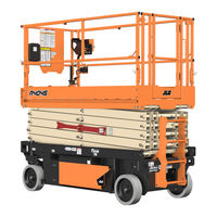
JLG 4045R Service Maintenance Manual (180 pages)
Brand:
JLG
| Category:
Scissor Lifts
| Size: 14.61 MB
Table of Contents
Table of Contents
5
Subject - Section, Paragraph
13
Specifications
13
Specification
13
Platform Capacities
14
Machine Dimensional Data
14
Tires
14
Batteries
15
Motors
15
Electrical System
16
Limit Switch Activation
17
Tilt Alarm
17
High Drive Speed Cutout
17
Lubrication
17
Lubrication Capacities
17
Hydraulic Oil
17
Lubrication Specifications
18
Hydraulic Pressure Settings
20
Hydraulic Cylinder Specifications
20
Serial Number Location
20
Critical Stability Weights
21
Major Component Weights
21
Torque Requirements
21
Torque Charts
22
General
27
Machine Preparation, Inspection, and Maintenance
27
Preparation, Inspection, and Maintenance
27
Pre-Start Inspection
27
Pre-Delivery Inspection and Frequent Inspection
27
Annual Machine Inspection
27
Preventative Maintenance
27
Preventive Maintenance and Inspection Schedule
29
Maintenance and Inspection Schedule Codes
29
Footnotes
31
Service Maintenance Components
32
Scissor Arm - Safety Prop
32
Hydraulic Oil Check Procedure
33
2.4 Service and Guidelines
34
General
34
Safety and Workmanship
34
Cleanliness
34
Components Removal and Installation
34
Component Disassembly and Reassembly
34
Pressure-Fit Parts
34
Bearings
34
Gaskets
34
Bolt Usage and Torque Application
34
Hydraulic Lines and Electrical Wiring
35
Hydraulic System
35
Lubrication
35
Battery
35
2.5 Lubrication and Information
35
Hydraulic Oil
35
Changing Hydraulic Oil
35
2.6 Cylinder Drift Test
36
Platform Drift
36
Cylinder Drift
36
Pins and Composite Bearing Repair Guidelines
36
Chassis & Scissor Arms
37
Left and Right Side Component Compartments
37
Battery Removal/Maintenance
38
Battery Quick-Disconnect (if Equipped)
38
Battery Maintenance and Safety Practices
39
Battery Charging
39
Delta-Q - Battery Charger
40
Green Power - Battery Charger (China (GB) Only)
40
Eagle Performance - Battery Charger
40
Battery Charger Maintenance
41
DC/Ac Power Inverter Installation - Option
45
Logic Control Module Installation
46
Main Power Contactor Relay and Pump Control Module
47
Pump Control Module
48
Removal
48
Installation
48
Ground Control Station - Folding Cover
50
Components Location
50
Removal
50
Installation
50
Ground Control Station - Fixed Cover
52
Components Location
52
Removal
52
Installation
52
3.10 Platform Control Station
54
Installation/Removal
55
Control Station Disassembly
55
Joystick Controller
57
3.11 Tilt Sensor Installation
58
Tilt Sensor Removal
58
3.12 Elevation Sensor
59
Elevation Sensor Installation
60
3.13 Pot-Hole Protection System Components
61
3.14 Steer and Spindle Assembly Components
62
Drive Motor Covers Installation - Option
63
Tire Wear and Damage
64
Wheel and Tire Replacement
64
Wheel Installation
64
Arms and Platform Positioning and Support
65
3.16 Platform Removal
65
3.17 Scissor Arms Removal
65
Removing Scissor Arm Assembly as a Complete Unit
65
Removing/Installing Scissor Arms Individually
65
Hydraulics
75
Cylinders - Theory of Operation
75
Valves - Theory of Operation
75
Solenoid Control Valves (Bang-Bang)
75
Relief Valves
75
Crossover Relief Valves
75
Proportional Valve
75
Manual Descent Valve
75
Pump/Motor
76
Pump Motor Electrical Evaluation
76
Hydraulic Tank Installation
78
Hydraulic Oil Check Procedure
79
Hydraulic Pump and Electric Motor Assembly
80
Pump/Motor Removal
80
Pump/Motor Disassembly
81
Pump/Motor Assembly
81
Pump/Motor Installation
81
Hydraulic Manifold Valve Installation
82
Hydraulic Manifold Assembly - Component Torque
84
Hydraulic Hose Routing
85
Lift Cylinder - Lower
85
Lift Cylinder - Upper
85
Steer Cylinder
85
Drive Motor Installation
86
Hydraulic Brake Installation
87
Hydraulic Brake Release
87
Pressure Setting Procedure
88
Main Relief
88
Lift up Relief
88
Steer Relief
88
4.10 Cylinder Checking Procedure
89
4.11 Lift Cylinder Removal/Installation
89
4.12 Lower Lift Cylinder
90
Disassembly
90
Assembly
90
4.13 Upper Lift Cylinder
90
4.14 Cylinder Repair
94
Disassembly
94
Cleaning and Inspection
95
Assembly
95
Jlg Control System
99
Hand Held Analyzer
99
Diagnostic Port
99
To Connect the Hand Held Analyzer
99
Using the Analyzer
101
Changing the Access Level of the Hand Held Analyzer
102
Adjusting Parameters Using the Hand Held Analyzer
103
Machine Setup
103
Joystick Calibration
104
Tilt Sensor Calibration
104
Tilt Sensor Failure Troubleshooting
104
Elevation Sensor Calibration
105
Updating Software
105
Machine Configuration Programming Information
110
Machine Model Adjustment (Personality Settings)
111
Lss (Load Sensing System) Service
113
Theory of Operation
113
LSS Component Locations
114
Analyzer Information
115
Personalities Menu
115
Diagnostic Menu
115
Calibration Preparation
117
Calibration and Verification Procedures
118
Empty Platform (Load 0%) Calibration
118
Loaded Platform (Load 110%) Calibration
118
LSS Verification
118
Partial Height Calibration
119
Testing
119
Lss Connector Pin Assignments
120
Lss Troubleshooting
121
Diagnostic Trouble Codes
123
Introduction
123
System Fault/Dtc Indication
123
Diagnostic Trouble Codes (Dtc)
123
Dtc Check Tables
124
General Electrical Information & Schematics
145
General
145
Multimeter Basics
145
Grounding
145
Backprobing
145
Min/Max
145
Polarity
145
Scale
145
Voltage Measurement
146
Resistance Measurement
146
Voltage Measurement (DC)
146
Continuity Measurement
147
Current Measurement
147
Current Measurement (DC)
147
Continuity Measurement over Long Distances
148
Requirements
148
Procedure
148
Applying Silicone Dielectric Compound to Amp Connectors
149
Installation of Dielectric Grease
149
Deutsch HD, DT, DTM, DRC Series
150
AMP Seal
150
AMP Mate-N-Lok
151
DIN Connectors
152
Exclusions
152
Amp Connector
155
Assembly
156
Connector Assembly (2 of 4)
156
Disassembly
157
Wedge Lock
158
Service - Voltage Reading
159
Working with Deutsch Connectors
160
DT/DTP Series Assembly
160
DT/DTP Series Disassembly
160
HD30/HDP20 Series Assembly
160
HD30/HDP20 Series Disassembly
161
Switches
162
Basic Check
162
Limit Switches
162
Automatic Switches
163
Switch Wiring - Low Side, High Side
163
Electrical Schematics
164
Electrical Schematic
164
Hydraulic Schematics
176
Hydraulic Schematic
176
Advertisement
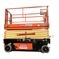
JLG 4045R Operation And Safety Manual (131 pages)
Brand:
JLG
| Category:
Boom Lifts
| Size: 12.26 MB
Table of Contents
Table of Contents
8
Section - Paragraph, Subject Page
13
Table of Contents
13
Section 1 - Safety Precautions
14
General
14
Pre-Operation
15
Operator Training and Knowledge
15
Workplace Inspection
15
Machine Inspection
16
Operation
17
General
17
Trip and Fall Hazards
18
Electrocution Hazards
19
Tipping Hazards
20
Minimum Approach Distances (M.A.D.)
20
Crushing and Collision Hazards
22
Towing, Lifting, and Hauling
24
Maintenance
24
Maintenance Hazards
24
Battery Hazards
25
Section 2 - User Responsibilities, Machine Preparation and Inspection
26
Personnel Training
26
Operator Training
26
Training Supervision
26
Operator Responsibility
26
Machine Familiarization
27
Preparation, Inspection, and Maintenance
27
Pre-Start Inspection
29
Daily Walk-Around Inspection
32
Daily Walk-Around Inspection
33
Function Check
34
Section 3 - Machine Controls, Indicators and Operation
37
General
37
Description
37
Operating Characteristics and Limitations
38
Placards
38
Capacities
38
Stability
38
Platform Loading
38
Machine Control Locations
39
Location of Machine Controls
39
Battery Charging
40
Ground Control Station
41
Ground/Platform/Off Key Selector Switch
42
Platform Lift/Lower Switch
42
Inverter ON/OFF Switch (if Equipped)
42
Ground Emergency Stop Switch
43
Hourmeter
43
Overload Indicator
43
MDI Indicator (if Equipped)
43
MDI Indicator
44
Platform Manual Descent Control
45
Location of Manual Descent Control
45
Platform Control Station
46
Platform Control Station (Module P/N 1001224873)
46
Platform Control Station (Module P/N 1001228112)
47
Platform Emergency Stop Switch
48
Lift/Drive Select Switch
48
Forward/Reverse/Lift/Lower Direction Decal
48
Drive/Lift/Steer Joystick Control
49
Steering and Traveling
49
Steering
50
Traveling Forward and Reverse
50
Raising and Lowering Platform
50
Grade and Sideslope Definition
51
Arm Guards (if Equipped)
52
Overload Indicator (LSS)
52
Tilt Indicator Warning Light and Alarm
52
Variable Tilt - Platform Restricted Height Indicator
52
Horn
53
Battery Charge Indicator
53
System Fault Indicator
53
Alarm
54
Indoor/Outdoor Operation Indicator
54
Indoor/Outdoor Operation Mode Switch
54
Low/High Drive Speed
54
3.10 Platform Extension
55
Platform Deck Extension
55
Platform Rails Fold-Down Procedure
56
Platform with Dual Rail Extension Deck
56
Platform with Dual Rail Extension - Fold down
57
Platform with Rail in Rail Extension Deck
58
Platform with Rail in Rail Extension - Fold down
59
3.12 Parking and Stowing Machine
60
3.13 Machine Lifting and Tie down
61
Lifting
61
Fork Lift Pockets - Location
61
Tie down
62
3.14 Towing
64
Hydraulic Brake Release
64
Hydraulic Brakes - Manual Disengage
64
Section 4 - Emergency Procedures
65
General Information
65
Emergency Operation
65
Operator Unable to Control Machine
65
Platform Caught Overhead
65
Righting of Tipped Machine
65
Platform Manual Descent
66
Incident Notification
67
Section 5 - General Specifications and Maintenance
70
Introduction
70
Other Publications Available Specific to this Machine
70
Operating Specifications
71
Platform Capacities
73
Machine Dimensional Data
74
Tires
74
Batteries
75
Electrical System
76
Battery Charger Specifications
76
Critical Stability Weights
77
Lubrication
77
Lubrication Capacities
77
Lubrication Specifications
77
Hydraulic Oil Operating Temperature Chart
78
Operator Maintenance
79
Scissor Arm - Safety Props
79
Scissor Arm - Safety Props
80
Hydraulic Oil Check Procedure
81
Hydraulic Oil Check Procedure
82
Hydraulic Oil Fill Procedure
82
Delta-Q - Battery Charger
83
Green Power - Battery Charger (China (GB) Only)
83
Eagle Performance - Battery Charger
84
Battery Maintenance and Safety Practices
85
Battery Quick-Disconnect (if Equipped)
85
Battery Fluid Level
85
Tire Wear and Damage
86
Wheel and Tire Replacement
86
Wheel Installation
87
Supplemental Information
88
Decal Installation
89
Machine Decal Installation
90
Machine Decal Installation Chart - 4045R
91
Diagnostic Trouble Codes (Dtc)
92
Diagnostic Trouble Codes (DTC)
93
Section 6 - Accessories
103
DC/Ac Power Inverter
106
Safety Precautions
106
Preparation and Inspection
107
Operation
107
Quikwelder
107
JLG Quickwelder Installation
108
JLG Quickwelder Components
108
Safety Precautions
109
Preparation and Inspection
109
Operation
109
Workstation
110
Workstation Installation
110
Safety Precautions
111
Preparation and Inspection
111
Operation
111
Electrician's Tree
112
Electrician's Tree Installation
112
Safety Precautions
113
Preparation and Inspection
113
Operation
113
Pipe Racks
114
Pipe Rack Installation
114
Safety Precautions
115
Preparation and Inspection
115
Operation
115
Panel Carrier
116
Panel Carrier Installation
116
Safety Precautions
117
Preparation and Inspection
117
Operation
117
Vise
118
Machinist's Vise Installation
118
Safety Precautions
119
Preparation and Inspection
119
Operation
119
Platform Work Lights
120
Operation
120
Work Lights Installation
120
Platform Rail Padding
121
Platform Rail Padding Components
121
6.10 Anti-Vandalism Package
122
A-VP Covers Open
122
6.11 Rail Mounted Platform Extension Handles
123
Operation
123
Platform Extension Handles Installation
123
Operation
124
6.13 Magnetic Gate Latch
125
Operation
125
Magnetic Gate Latch Installation
125
Section 7. Inspection and Repair Log
127
Inspection and Repair Log
127
Advertisement
Related Products
JLG 430LRT
JLG 4069LE
JLG 4009
JLG 400S
JLG 400SJ
JLG 4017
JLG 4017PS
JLG 4017RS
JLG 400SC
JLG 400CRT
JLG Categories
Boom Lifts
Lifting Systems
Scissor Lifts
Construction Equipment
Forklifts
More JLG Manuals
Login
Sign In
OR
Sign in with Facebook
Sign in with Google
Upload manual
Upload from disk
Upload from URL