Sign In
Upload
Manuals
Brands
JCM GLOBAL Manuals
Cash Register
iVIZION LD
JCM GLOBAL iVIZION LD Manuals
Manuals and User Guides for JCM GLOBAL iVIZION LD. We have
1
JCM GLOBAL iVIZION LD manual available for free PDF download: Operation And Maintenance Manual
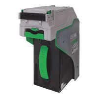
JCM GLOBAL iVIZION LD Operation And Maintenance Manual (124 pages)
Next-Generation Banknote Acceptor Unit
Brand:
JCM GLOBAL
| Category:
Cash Register
| Size: 9.83 MB
Table of Contents
Table of Contents
3
1 General Information
15
Description
15
Ivizion Units
15
Model Number Specifications
16
Type Descriptions
16
Software Descriptions
16
Precautions
16
User Cautions
16
Installation Cautions
16
Mounting, Dismounting & Transportation
17
Preventive Maintenance
17
Banknote Fitness Requirements
17
Reference Paper Use Precautions
17
Figure 1-3 Unacceptable Banknotes
17
Primary Features
18
Component Names
18
Specification (Ivizion SS Version)
19
Technical Specifications
19
Environmental Specifications
19
Electrical Specifications
20
Structural Specifications
20
Specification (Ivizion LD Version)
21
Technical Specifications
21
Environmental Specifications
21
Electrical Specifications
22
Structural Specifications
22
Ivizion Entire Unit Outside Dimensions
23
Ivizion SS Version Installation/Maintenance Space Requirements
24
Ivizion LD Specification Unit Dimensions
25
Various Cash Box Unit Dimensions
26
Standard Cash Box Outside Dimensions
26
Large Cash Box Outside Dimensions
26
International Compliance
27
Technical Contact Information
28
Americas & Oceania
28
JCM American
28
Europe, Africa, Russia & Middle East
28
JCM Europe Gmbh
28
UK & Ireland
28
JCM Europe (UK Office)
28
Asia
28
JCM Gold (HK) Ltd
28
Japan Cash Machine Co, Limited (HQ)
28
2 Installation
29
Installation Process
29
Cable Interconnection
30
DIP Switch Configurations
30
Primary LED Indications
30
Denomination INHIBIT DIP Switch Settings
30
Connector Pin Assignments
31
Connector Pin Assignments (Continued 1)
32
Connector Pin Assignments (Continued 2)
33
Connector Pin Assignments (Continued 3)
34
Connector Pin Assignments (Continued 4)
35
Connector Pin Assignments (Continued 5)
36
Preventive Maintenance
36
Retrieving Banknotes
36
Clearing a Banknote Jam
36
Cleaning Procedure
37
Sensor Cleaning Procedure
37
Ivizion Optional LD Version Unit Installation
37
Ivizion Sensor Locations
38
Standard Interface Circuit Schematics
39
Interface Circuit Schematics (Continued 1)
40
Figure 2-13 Ivizion RS232C Circuit Interface Schematic Diagram
40
Interface Circuit Schematics (Continued 2)
41
Figure 2-15 Ivizion TTL Circuit Interface Schematic Diagram
41
Interface Circuit Schematics (Continued 3)
42
Figure 2-16 Ivizion LED Circuit Interface Schematic Diagram
42
Operational Flowchart (Continued 1)
43
Figure 2-18 Ivizion SS Banknote Acceptor Operational Flowchart (Part 2 Validating)
44
Operational Flowchart (Continued 2)
45
Figure 2-19 Ivizion LD Banknote Acceptor Operational Flowchart (Part 2 Validating)
45
3 Communications
47
Americas & Oceania
47
JCM American
47
Europe, Africa, Russia & Middle East
47
JCM Europe Gmbh
47
UK & Ireland
47
JCM Europe (UK Office)
47
Asia
47
JCM Gold (HK) Ltd
47
Japan Cash Machine Co, Limited (HQ)
47
4 Disassembly/Reassembly
49
Tool Requirements
49
Pusher Unit Timing Belt Removal
49
Figure 4-6 Right Frame Outer "R" Removal
50
Figure 4-7 Left Frame Outer "L" Removal
50
Figure 4-4 Stacker Guide Removal
50
Home Position Sensor Board/Home Position Sensor, FFC & Interface Connector Board Removals
51
Figure 4-8 Timing Belt Removal
51
Figure 4-9 TR Bottom Cover Removal
51
Figure 4-10 TR Side Cover "A" Removal
51
Figure 4-11 Home Position Sensor Board, Home Position Sensor FFC Assembly
51
RFID Module & Harness Removals
52
Validation CPU & Controller CPU Board Removals
52
USB FPC, Power FPC & Interface FPC Cable Removals
52
Figure 4-12 RFID Module & Harness Removal
52
Figure 4-13 CPU Board Module Removal
52
Figure 4-14 Extension Memory Board Removal
52
Figure 4-15 Validation CPU Board and Control CPU Board Removal
52
Validation Unit Harness Removal
53
Interrupter Board Removal
53
Motor Unit Timing Belt Removal
53
Figure 4-16 Motor Module Removal
53
Figure 4-17 USB FPC, Power FPC & Interface FPC Cable Removal
53
Figure 4-18 Validation Unit Harness Removal
53
Figure 4-19 Interrupter Board Removal
53
Figure 4-20 Timing Belt Removal
53
Stacker Motor & Transport Motor Removals
54
Bezel Retainer Clips a & B Removal
54
Sensor Transfer Board/Cis Ffc/Transmissive Light FFC & Upper UV FPC Sensor Removals
54
Figure 4-21 Timing Belt Reassembly Path
54
Figure 4-22 Stacker & Transport Motor Removal
54
Figure 4-23 Bezel Retainer Chips A&B Removal
54
Validation Sensor Board Assembly Removal
55
Figure 4-24 Upper Cover Removal
55
Figure 4-25 Sensor Transfer Board Assembly, CIS FFC, Transmissive Light & Upper UV FPC Cable Removal
55
Figure 4-26 Ivizion Head Cover a Removal
55
Figure 4-27 Validation Sensor Board Assembly Removal
55
Validation Sensor FPC Cable Removals
56
Cis/Transmissive Light & Upper UV Sensor Removals
56
Figure 4-28 Validation Sensor FPC Removal
56
Figure 4-29 Validation Sensor FPC Reassembly
56
Figure 4-30 Upper Validation Part Removal
56
Figure 4-31 Ivizion Head BG85B Removal
56
CIS/CIS Fpc/Lower UV Sensor & Lower UV FFC Removal
57
Figure 4-32 CIS, Transmissive Light & Upper UV Sensor Removal
57
Figure 4-33 Ivizion BG 85A HEAD Removal
57
Figure 4-34 Lower Validation Part Removal
57
Validation Unit Timing Belt Removal
58
Reassembly Cautions
58
Figure 4-35 CIS, CIS FPC, Lower UV Sensor & Lower UV FFC Removal
58
Figure 4-36 Timing Belt Removal
58
Figure 4-37 Timing Belt Replacement
58
Figure 4-38 Upper/Lower UV Sensors Location
58
5 Wiring Diagrams
59
Ivizion System Wiring Diagram
59
Figure 5-1 Ivizion System Wiring Diagram
59
6 Calibration and Testing
61
Download and Installation Workbench Tool Requirements
61
Application Software Installation
61
Figure 6-1 Tool and Harness Connections
61
Figure 6-2 USB Cable Type Requirement
61
Figure 6-3 Setup.exe File Location
61
Figure 6-4 Install Shield Wizard Screen
61
Driver Installation Procedure
62
Figure 6-5 Customer Information Screen
62
Figure 6-6 Destination Folder Screen
62
Figure 6-7 Current Settings Confirmation
62
Figure 6-8 Installation Completion Screen
62
JCM Tool Suite Standard Edition Mode
63
Software Download Tool Requirements
63
Figure 6-11 Hardware Update Wizard Screen 3
63
Figure 6-13 Normal Mode Selection
63
Figure 6-14 Test Mode Selection
63
Figure 6-15 Required Software Download Tools
63
Software Download Procedures
64
Download the Upgrade Program
64
Figure 6-16 DIP Switches All off
64
Figure 6-18 JCM Tool Suite Standard Edition Screen Pull-Down Menu
64
Figure 6-19 Browse Screen Button Location
64
Figure 6-20 Ivizion Software Program Selection
64
Downloading the Program First Time
65
Figure 6-21 Download Progress Screen 1
65
Figure 6-23 DIP Switches 6, 7, & 8 on
65
Figure 6-24 JCM Tool Suite Standard Edition Screen 2
65
Figure 6-26 Browse Screen Button Location
65
Calibration
66
When to Calibrate
66
Calibration Order
66
Calibration Tool Requirements
66
Figure 6-27 Ivizion Software Program Selection
66
Ivizion Sensor Calibration Order
66
Placing the KS-072 Reference Paper
67
Calibration Procedure
67
Calibration Only
67
Figure 6-30 Remote Calibration Tools Required
67
Figure 6-31 Reading KS-072 Reference Paper
67
Figure 6-34 DIP Switch #8 on
67
Figure 6-35 JCM Tool Suite Standard Edition Screen 3
67
Figure 6-36 Ivizion Calibration Ver.X.XX Screen
68
Figure 6-37 Feed-Out Calibration Proceeding Screen
68
Figure 6-39 Calibration Information Screen 2
68
Figure 6-40 Pusher Plate Release Location
68
Figure 6-41 Cardboard Setting Location
68
Figure 6-42 Exit Calibration Proceeding Screen
69
Figure 6-44 UV Calibration Proceeding Screen
69
Figure 6-47 CIS Calibration Proceeding Screen
69
Calibration Plus Serial Number Writing
70
Performance Tests
70
Figure 6-49 Calibration Value Writing Screen
70
Figure 6-50 Calibration Complete Screen
70
Figure 6-51 Ivizion Calibration Service Suite Edition Screen
70
Figure 6-52 Setting Manufacture No. Screen
70
Figure 6-53 Calibration Value Writing Screen
70
Figure 6-55 PC Performance Test Tools Required
71
Figure 6-56 DIP Switch #8 Set on
71
Figure 6-57 JCM Tool Suite Standard Edition Screen
71
Figure 6-58 Ivizion Test Item Verx.XX Screen
71
PC Performance Test Items
71
PC Performance Test Preparation
71
Performance Test Items Using a PC
71
Performance Test Tool Requirement Using a PC
71
Performance Test Procedures
72
Any Motor Test
72
LED Indicator Test
72
Figure 6-59 Start, Stop & Exit Screen Button
72
Figure 6-60 Transport Motor Normal Forward Test Screen
72
Figure 6-61 LED Indicator Test Screen
72
Sensor ON/OFF Test
73
Banknote Acceptance Test
73
Figure 6-62 Sensor ON/OFF Test Screen
73
Figure 6-63 Denomination Indication Location
73
Sensor Actions and Conditions
73
ICB Function Setting (Barcode Coupon)
74
DIP Switch ON/OFF Test
74
Figure 6-64 ICB Function Test Screen
74
External DIP Switch Performance Test Procedure Settings
75
Figure 6-66 DIP Switch ON/OFF Test Screen 2
75
Figure 6-67 Calibration Tool Requirements
75
Performance Test DIP Switch Settings
75
Performance Test Tool Requirement Using an External DIP Switch Box
75
Performance Tests Using the External DIP Switch Procedures
75
Ivizion Utility Tools
76
Icb/Image Setting Tool Requirements
76
Icb/Image Setting Change Preparation
76
CIS Image Tool
76
Figure 6-68 ICB Setting Tool Requirements
76
Figure 6-69 JCM Tool Suite Standard Edition
76
ICB Function Setting
77
Setting ICB Enable/Disable Functions
77
Figure 6-71 Empty CIS IMAGE Screen
77
Figure 6-72 Last Acceptance CIS IMAGE Screen
77
Figure 6-73 Ivizion Utility Tool Version X.XX for Suite Edition Screen 2
77
Figure 6-74 ICB Function Screen
77
Figure 6-75 Enable Setting Completion
78
Figure 6-76 Disable Setting Completion
78
Figure 6-77 ICB Current Status Screen
78
Figure 6-78 Machine Number Setting
78
Figure 6-79 Machine Number Setting Completion
78
Figure 6-80 Machine Number Indication
78
ICB Function Operational Condition
79
Figure 6-81 Inhibit Screen Button Location
79
Figure 6-82 Inhibit Setting Completion
79
Figure 6-83 ICB System Status Indication
79
ICB Setting Function Operational Condition
79
7 Exploded Views & Parts Lists
81
Ivizion Entire Unit Exploded View
81
Figure 7-1 Ivizion Entire Unit Exploded View Diagram
81
Ivizion Entire Unit Parts List
82
Ivizion Validation Unit 1 Exploded View
83
Figure 7-2 Ivizion Validation Unit 1 Exploded View
83
Ivizion Validation Unit 1 Parts List
84
Ivizion Validation Unit 2 Exploded View
85
Figure 7-3 Ivizion Validation Unit 2 Exploded View
85
Ivizion Validation Unit 2 Parts List
86
Ivizion Validation Unit 3 Exploded View
87
Figure 7-4 Ivizion Validation Unit 3 Exploded View
87
Ivizion Validation Unit 3 Parts List
88
Ivizion Transport Unit 1 Exploded View
89
Figure 7-5 Ivizion Transport Unit 1 Exploded View
89
Ivizion Transport Unit 1 Parts List
90
Ivizion Transport Unit 2 Exploded View
91
Figure 7-6 Ivizion Transport Unit 2 Exploded View
91
Ivizion Transport Unit 2 Parts List
92
Table 7-6 Ivizion Transport Unit 2 Parts List
92
Ivizion Transport Unit 3 Exploded View
93
Figure 7-7 Ivizion Transport Unit 3 Exploded View
93
Ivizion Transport Unit 3 Parts List
94
Table 7-7 Ivizion Transport Unit 3 Parts List
94
Ivizion Transport Unit 4 Exploded View
95
Figure 7-8 Ivizion Transport Unit 4 Exploded View
95
Ivizion Transport Unit 4 Parts List
96
Table 7-8 Ivizion Transport Unit 4 Parts List
96
Ivizion Transport Unit 5 Exploded View
97
Figure 7-9 Ivizion Transport Unit 5 Exploded View
97
Ivizion Transport Unit 5 Parts List
98
Table 7-9 Ivizion Transport Unit 5 Parts List
98
Ivizion Transport Unit 6 Exploded View
99
Figure 7-10 Ivizion Transport Unit 6 Exploded View
99
Ivizion Transport Unit 6 Parts List
100
Table 7-10 Ivizion Transport Unit 6 Parts List
100
Ivizion SS Version Frame Unit Exploded View
101
Figure 7-11 Ivizion SS Version Frame Unit Exploded View
101
Ivizion SS Version Frame Unit Parts List
102
Table 7-11 Ivizion SS Version Frame Unit Parts List
102
Ivizion Cash Box Unit 1 Exploded View
103
Figure 7-12 Ivizion Cash Box Unit 1 Exploded View
103
Ivizion Cash Box Unit 1 Parts List
104
Table 7-12 Ivizion Cash Box Unit 1 Parts List
104
Ivizion Cash Box Unit 2 Exploded View
105
Figure 7-13 Ivizion Cash Box Unit 2 Exploded View
105
Ivizion Cash Box Unit 2 Parts List
106
Table 7-13 Ivizion Cash Box Unit 2 Parts List
106
Ivizion Cash Box Unit 3 Exploded View
107
Figure 7-14 Ivizion Cash Box Unit 3 Exploded View
107
Ivizion Cash Box Unit 3 Parts List
108
Table 7-14 Ivizion Cash Box Unit 3 Parts List
108
Ivizion LD Version Frame Exploded View
109
Figure 7-15 Ivizion LD Version Frame Exploded View
109
Ivizion LD Version Frame Parts List
110
Table 7-15 Ivizion LD Version Frame Parts List
110
Ivizion Optional Components Exploded Views
111
Figure 7-16 Ivizion Optional Components Exploded Views
111
Ivizion Optional Components Parts List
112
Table 7-16 Ivizion Optional Components Parts List
112
8 Index
113
A Troubleshooting
115
Introduction
115
Troubleshooting Overview
115
Malfunction LED Error Codes
115
LED Indication Conditions
115
Table A-1 LED Code Condition
115
Error, Jam and Reject Code Tables
116
Table A-2 LED Error Codes
116
Jam Error Codes
118
Table A-3 Jam LED Flash Error Codes
118
Reject Error Code
119
Table A-4 LED Reject Codes
119
Maintenance Equipment
120
Ivizion Maintenance Equipment
120
Reference Paper Handling
120
Figure A-1 Additional Maintenance Equipment Requirements
120
Table A-5 Additional Maintenance Equipment Parts List
120
B Glossary
121
Advertisement
Advertisement
Related Products
JCM GLOBAL iVIZION Series
JCM GLOBAL iVIZION SS
JCM GLOBAL iVIZION2 Series
JCM GLOBAL Categories
Bank Note Validator
Industrial Equipment
Banknote Counter
Cash Register
Ultrasonic Jewelry Cleaner
More JCM GLOBAL Manuals
Login
Sign In
OR
Sign in with Facebook
Sign in with Google
Upload manual
Upload from disk
Upload from URL