Sign In
Upload
Manuals
Brands
ITW Dynatec Manuals
Industrial Equipment
DM55 DynaDrum
User Manuals: ITW Dynatec DM55 DynaDrum Hot Melt Drum
Manuals and User Guides for ITW Dynatec DM55 DynaDrum Hot Melt Drum. We have
1
ITW Dynatec DM55 DynaDrum Hot Melt Drum manual available for free PDF download: Technical Documentation Manual
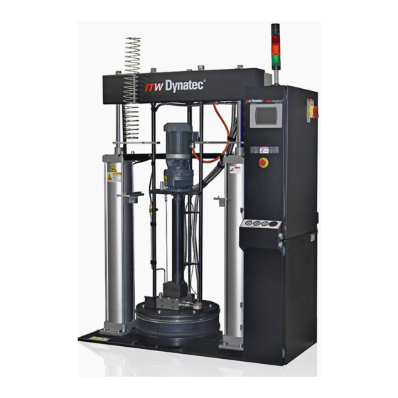
ITW Dynatec DM55 DynaDrum Technical Documentation Manual (224 pages)
Bulk Adhesive Melter With Piston Pump & Controller V6 Touch Panel Rev.2.19
Brand:
ITW Dynatec
| Category:
Industrial Equipment
| Size: 17 MB
Table of Contents
Information about this Manual
2
Index
3
Table of Contents
3
Chapter 1 Declaration of Conformity
7
Chapter 2 Safety Instructions
9
General Considerations
9
Warning Labels
9
Safety Symbols in this Manual
10
Safe Installation and Operation
10
Explosion/ Fire Hazard
11
Choice of Adhesive
11
Special Safety Considerations When Using Reactive HMPUR Adhesives
11
Eye Protection & Protective Clothing
13
Electrical
13
Lockout/ Tagout
13
High Temperatures
14
High Pressure
14
Protective Covers
14
Servicing, Maintenance
15
Secure Transport
15
Treatment for Burns from Hot Melt Adhesives
16
Measures in Case of Fire
16
Keep Attention to Environmental Protection Standards
17
Chapter 3 Description and Technical Specs
19
Applicable Safety Regulations
19
Intended Use
19
Unintended Use, Examples
19
Residual Risks
20
Technical Changes
20
Using Foreign Components
20
Setting-Up Operation
20
Description
21
Two-Hand-Control-Buttons (Left & Right-Confirm-Buttons)
22
System Status Lights
22
Mechanical High-Temperature Protection
22
RTD Sensors
22
Specifications
23
Model Designation Guide
26
Chapter 4 Installation
27
Conditions for Set-Up and Mounting
27
Installation
28
Quality of Compressed Air
29
Chapter 5 Setting-Up Operation, Daily Operation
31
Advices for the Setting-Up Operation
31
Setting-Up Operation, Daily Operation
33
Open/ Close the Main Panel Box Door
33
To Turn Main Power On/Off
33
Operating Switches and Buttons
33
Procedure to Resume Production after Use of Emergency Stop
34
Preparing a New Drum for Melting
34
Pneumatic Controls
34
Operator Adjustments
36
Platen Position Sensor
37
Bulk Melter Startup Procedure, Daily Operation
38
Drum Change-Out
42
Switching the Unit off
44
Chapter 6 Controller V6 Touch
45
Controller Set-Up
45
Helpful Tips for the User
45
Temperature Control Functions in General
45
Software & Hardware Versions
45
Defining Dynacontrol Temperature Control Terms
46
Program Your System's Parameters
48
Numeric Entry Keypad
48
Alphabetic Entry Keypad
49
Main Screen
50
Temperature Zones Set Screen
54
Zone On/Off Switch on the Numeric Entry Keypad
55
Pump Overview Screen
56
Pump Control Screen/ Linear Line Speed
58
Extended Pump Mode Settings Screen, Linear Line Speed, Pressure Control
60
Pump Control/ Pressure Control Screen
62
Automatic Ramp Compensation at DM55 with Gear Pump
64
Control Switch On/Off and Standby Switch
66
Systems Screen
68
Settings Screen
70
Heating Priority Screen
71
Zone Configuration Screen
72
Zone Settings
73
Fieldbus Setup Screen
75
General Settings Screen
76
Temperature Settings
76
Standby Settings
78
Drum Calibration
80
Level Control Settings
82
Pressure Zero Calibration
84
Customer Zone Names
86
Support
88
Recipes Screen
89
Time & Scheduler Screen
91
Log Book Screen
94
Security Screen
95
System Info Screen
97
License Management Screen
98
Software Licenses
99
Acknowledge Button
100
Faults/ Alarms
101
Operator Response to Error Indication Alarms
101
XIO Template Settings, Module #1
102
Modules and Printed Circuit Boards (Pcbs)
103
V6 Base Module PN 115734
104
V6 Temperature Module PN 115735
108
Standard V6 Zone Table, Drum Unloader DM55
109
V6 Power Module PN 823306
110
V6 Motor Module PN 116823
111
V6 Solid State Relay (SSR) Adapter PCB Assembly PN 118584
112
Optional V6 BUS Communications Module PN 118125
113
V6 Extended I/O Module PN 117648
114
Optional Printed Circuit Boards
114
Chapter 7 Maintenance and Repair Notes
115
Security Advices for Maintenance and Repair
115
Maintenance Plan
116
Piston Pump Oil Cavity
117
Piston Pump Inlet Check Valve Cleaning
117
Draining of Supply Air Filter/ Regulator
118
Clamshell Adjustments
118
Special Maintenance for PUR Applications
118
Piston Pump Assembly Replacement
119
Pump Disassembly
120
Platen Removal
122
Platen Seal Replacement
123
Electrical Parts Replacement
127
Chapter 8 Troubleshooting
129
Troubleshooting Notes
129
Mechanical Troubleshooting Guide (for Piston Pump Models)
131
Electrical Troubleshooting Guide
134
Heaters in Platen Core
135
Heaters in Piston Pump
136
RTD Sensors in Platen Core & Piston Pump
136
Piston Pump Flow Diagram
137
Motor Speed Control Drive
138
Accessing, Programming and Monitoring Motor Control Parameters
139
Chapter 9 Drawings and Bill of Materials
141
Notes
141
Frame and Panel Box Assemblies
142
Platen and Connector Kit Assemblies
144
Platen Vent Valve Assembly, PN 114295
146
Piston Pump Assembly, PN 114350
147
Air Motor Assembly, PN 114314
149
Piston Pump/ Air Motor Connection Replacement Parts
150
Remote Purge Kit, PN 116401
151
Piston Pump Pneumatic Assembly, 5 PSI Air Inject, PN 823064
152
Air Injection Replacement Parts
154
Piston Pump Valve Assembly, PN 823066
155
Junction Box Assembly, Piston Pump, PN 115945
157
Chapter 10 Options & Accessories
159
Level Control Kit Without Heated Ball Valve & Actuator Option, PN 806573
159
Heated 1" Ball Valve Option, PN 805732
159
Ball Valve Air Actuator Option, PN 806387
159
Pump Option
159
Full Clam Shell Option, PN 114126
159
Vent Hood Option, PN 114367
159
Pressure Transducer Kit PN 114717, Transducer Only PN 811475
159
Pallet Spacer Option, PN 114725
159
Purge Valve Heater Option, PN 115502
159
Platen Options
160
Platen Seal Options
160
Platen Guard, PN 116967
160
Purge Valve Heater, PN 115502
161
Pressure Transducer Kit, PN 114717
162
Drum-Present Sensor Kit, PN 114811
163
Cable Position Sensor Kit, PN 114812
164
Ball Valve Purge Kit, PN 114757
165
Vertical Air Inject Valve, PN 116859
166
Angled Air Inject, PN 117812
167
Pressure Relief Assembly, 3 Position, PN 823034
168
Pressure Relief Assembly, 2 Position, PN 823033
169
Pressure Gauge Assembly, Easy Spin, PN 819685
170
Optional V6 Communications Adapters/ Pcbs
170
Air Motor Rebuild Kits
171
Chapter 11 Recommended Spare Part Lists
173
Mechanical Parts
173
Parts Within the Controller Panel Box (240V, 400V or 480V)
173
Parts for Piston Pump Models
174
Pneumatic Parts
175
Miscellaneous
175
Chapter 12 Pneumatic Schematics
177
Pneumatic Schematic, Piston Pump, 5 PSI Air Inject, PN 823079
177
Pressure Relief Assembly, 3 Position (Optional), PN 823034
178
Pressure Relief Assembly, 2 Position (Optional), PN 823033
178
Chapter 13 Electrical Schematics
179
Bulk Melter DM55 240V
179
Schematics, 240V, PN 823172
179
Bulk Melter DM55 400V
181
Schematics, 400V, PN 823173
191
Bulk Melter DM55 480V
203
Schematics, 480V, PN 823174
203
Chapter 14 Appendix
217
Dynacontrol V6 / Fieldbus Options
217
Advertisement
Advertisement
Related Products
ITW Dynatec DYNAMELT D15 Series
ITW Dynatec DYNAMELT D25 Series
ITW Dynatec DYNAMELT D45 Series
ITW Dynatec DYNAMINI
ITW Dynatec DY 2008
ITW Dynatec DynaFiber UFD
ITW Dynatec DPC2
ITW Dynatec Dyna BFS
ITW Dynatec DYNAMINI 4-HOSE
ITW Dynatec Categories
Industrial Equipment
Paint Sprayer
Controller
Power Supply
More ITW Dynatec Manuals
Login
Sign In
OR
Sign in with Facebook
Sign in with Google
Upload manual
Upload from disk
Upload from URL