Table of Contents
Advertisement
Quick Links
Advertisement
Table of Contents
Troubleshooting

Related Manuals for ITW Dynatec DM55 DynaDrum


Summary of Contents for ITW Dynatec DM55 DynaDrum
- Page 1 Adhesive Application Solutions | ISO 9001 certified DM55 DynaDrum Bulk Adhesive Melter With Piston Pump & Controller V6 Touch Panel Rev.2.19 Technical Documentation, No. 21-18, Rev.2.19 ITW Dynatec An Illinois Tool Works Company www.itwdynatec.com...
-
Page 2: Information About This Manual
Hendersonville, TN 37075 40822 Mettmann SIP, Suzhou, 215122 26-11, Nishikamata 7-chome Germany China Ota-ku, Tokyo 144-0051, Tel. +1.615.824.3634 Tel. +49.2104.915.0 Tel. +86.512.6289.0620 Japan info@itwdynatec.com info@itwdynatec.de info@itwdynatec.cn Tel. +81.3.5703.5501 service@itwdynatec.com service@itwdynatec.de service@itwdynatec.cn info@itwdynatec.co.jp service@itwdynatec.co.jp Page 2 DM55 DynaDrum PP V6, Manual No.21-18, Rev.2.19... -
Page 3: Table Of Contents
4.1 Conditions for set-up and mounting .............. 27 4.2 Installation ....................28 4.3 Quality of compressed Air ................29 Chapter 5 Setting-up Operation, Daily Operation ....31 5.1 Advices for the setting-up operation ............. 31 DM55 DynaDrum PP V6, Manual No.21-18, Rev.2.19 Page 3... - Page 4 Operator Response to Error Indication Alarms ..............101 XIO Template Settings, Module #1 ..................102 6.3 Modules and Printed Circuit Boards (PCBs) ..........103 V6 Base Module PN 115734 ....................104 V6 Temperature Module PN 115735 ..................108 Page 4 DM55 DynaDrum PP V6, Manual No.21-18, Rev.2.19...
- Page 5 Remote Purge Kit, PN 116401 ....................151 Piston Pump Pneumatic Assembly, 5 PSI Air Inject, PN 823064 ......... 152 Air Injection Replacement Parts .................... 154 Piston Pump Valve Assembly, PN 823066 ................155 DM55 DynaDrum PP V6, Manual No.21-18, Rev.2.19 Page 5...
- Page 6 Schematics, 400V, PN 823173 ..................... 181 13.3 Bulk Melter DM55 480V ................183 Schematics, 480V, PN 823174 ..................... 183 Chapter 14 Appendix............185 DynaControl V6 / Fieldbus Options ..................185 Revisions ..........................186 Pressure Transducer Page 6 DM55 DynaDrum PP V6, Manual No.21-18, Rev.2.19...
-
Page 7: Chapter 1 Declaration Of Conformity
Chapter 1 ITW Dynatec Declaration of Conformity Chapter 1 Declaration of Conformity DM55 DynaDrum PP V6, Manual No.21-18, Rev.2.19 Page 7... - Page 8 ITW Dynatec Chapter 1 Declaration of Conformity This page intentionally left blank. Page 8 DM55 DynaDrum PP V6, Manual No.21-18, Rev.2.19...
-
Page 9: Chapter 2 Safety Instructions
2. Do not remove or deface any of the warning labels, signs and caution statements on the equipment. 3. Replace any warning labels, signs and caution statements which have been removed or defaced. Replacements are available from ITW Dynatec. DM55 DynaDrum PP V6, Manual No.21-18, Rev.2.19 Page 9... -
Page 10: Safety Symbols In This Manual
11. Never let the unit run unattended. 12. Operate the unit only in a faultless and fully functional condition. Check and make sure that all safety devices work in proper form! Page 10 DM55 DynaDrum PP V6, Manual No.21-18, Rev.2.19... -
Page 11: Explosion/ Fire Hazard
Choice of Adhesive Substance(s) being processed (e.g., melted, pumped, applied) by ITW equipment is at the discretion of the user and beyond ITW Dynatec’s control. Any health effects or other safety-related concerns arising from the melting of those particular substances (e.g., hazardous fumes) is the responsibility of the user to identify and mitigate. - Page 12 10. The use of air dryers such as ITW Dynatec PN 117944 or 117974 are recommended in humid environments. There are many advantages to using HMPURs. However, the proper handling of these unique adhesives is imperative to assure success without damage to equipment or injury to personnel.
-
Page 13: Eye Protection & Protective Clothing
3. Even after the equipment has been locked out, there may be stored energy in the application system, particularly in the capacitors within the panel box. To ensure that all stored energy is relieved, wait at least one minute after removing power before servicing electrical capacitors. DM55 DynaDrum PP V6, Manual No.21-18, Rev.2.19 Page 13... -
Page 14: High Temperatures
For this reason, always wear eye protection and protective clothing. 4. Either of the two High Pressure symbols shown may be used on ITW Dynatec equipment. 5. Keep the given operating pressure. -
Page 15: Servicing, Maintenance
3. Use only lifting devices that are suitable for the weight and the dimensions of the equipment (see drawing of the equipment). 4. The unit has to be transported upright and horizontally! 5. The unit has to cool down to room temperature before packaged and transported. DM55 DynaDrum PP V6, Manual No.21-18, Rev.2.19 Page 15... -
Page 16: Treatment For Burns From Hot Melt Adhesives
Foam extinguisher, Dry powder, Spray, Carbon dioxide (CO2), Dry sand. For safety reasons not appropriate extinguishing agents: None. Firefighting - burning electrical equipment: Appropriate extinguishing agents: Carbon dioxide (CO2), Dry powder. Page 16 DM55 DynaDrum PP V6, Manual No.21-18, Rev.2.19... -
Page 17: Keep Attention To Environmental Protection Standards
3. These matters have to be caught, kept, transported and disposed in appropriate reservoirs! 4. Dispose these matters according to the international, national and regional regulations. DM55 DynaDrum PP V6, Manual No.21-18, Rev.2.19 Page 17... - Page 18 ITW Dynatec Chapter 2 Safety Instructions This page intentionally left blank. Page 18 DM55 DynaDrum PP V6, Manual No.21-18, Rev.2.19...
-
Page 19: Chapter 3 Description And Technical Specs
If the unit is not used in accordance with this regulation, a safe operation cannot be guaranteed. The operator - and not ITW Dynatec - is liable for all personal injury or property damages resulting from unintended use! Intended use includes, that you •... -
Page 20: Residual Risks
Any kind of technical changes having impact to the security or the operational liability of the unit should only be done by written agreement of ITW Dynatec. Suchlike changes made without given a corresponding written agreement will lead to immediate exclusion of liability granted by ITW Dynatec for all direct and indirect subsequent damages. -
Page 21: Description
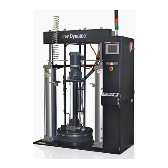
Description and Technical Specs 3.2 Description The ITW Dynatec DM55 DynaDrum™ Bulk Adhesive Melter is a stationary melter that combines a heated platen, pump and all controls needed to melt and dispense hot melt adhesives, sealants, PURs or coatings from a standard 55-gallon steel drum. -
Page 22: Two-Hand-Control-Buttons (Left & Right-Confirm-Buttons)
The mechanical thermostat automatically re-sets after the manifold temperature falls below 204°C (400°F). RTD Sensors The standard Dynamelt system uses 100-ohm platinum resistance temperature detector sensors for all temperature controls. Page 22 DM55 DynaDrum PP V6, Manual No.21-18, Rev.2.19... -
Page 23: Specifications
Air consumption at 60 pump cycles per minute ..548 liters/ minute @ 4.5 bar (19.4 CFM at 66 psig) Air Requirements: Operating air pressure range ............. 1.4 to 5.5 bar (20 to 80 psi) DM55 DynaDrum PP V6, Manual No.21-18, Rev.2.19 Page 23... - Page 24 Ready interlock .......................... yes Password protection ........................yes Sequential heating ........................yes Alarm output ..........................yes Sensor open alarm ........................yes Seven-day scheduler ........................ yes EtherNet/IP, Profibus, EtherCAT, Modbus/TCP interface ............yes Page 24 DM55 DynaDrum PP V6, Manual No.21-18, Rev.2.19...
- Page 25 Chapter 3 ITW Dynatec Description and Technical Specs Bulk Melter Installation Dimensions DM55 DynaDrum PP V6, Manual No.21-18, Rev.2.19 Page 25...
-
Page 26: Model Designation Guide
1 = Single-Hose Outlet Manifold, PUR 2 = Dual-Hose Outlet Manifold* 3 = Single-Hose Outlet Manifold, #24 JIC 4 = Single-Hose Outlet Manifold, Ball Valve Purge 5 = Dual-Hose Outlet Manifold, Ball Valve Purge * Standard. Page 26 DM55 DynaDrum PP V6, Manual No.21-18, Rev.2.19... -
Page 27: Chapter 4 Installation
Advices: • Check all screw connections at the unit and retighten if necessary. • Lay the cables and heated hoses so that no risk or least possible risk of stumbling occurs. DM55 DynaDrum PP V6, Manual No.21-18, Rev.2.19 Page 27... -
Page 28: Installation
(see Ch. 11 Recommended Spare Parts List for part nos.), mineral oil or a compatible solvent for your application. Consult ITW Dynatec for compatibility with the piston pump shaft seal and bearing. No disassembly is required to access the cavity. -
Page 29: Quality Of Compressed Air
≤ 1,000 ≤ -20 ≤ 10,000 ≤ +3 ≤ 100,000 ≤ +7 ≤ 5 ≤ +10 5-10 ≤ 0.5 0.5 - 5 5 - 10 > 10 > 10 > 10 DM55 DynaDrum PP V6, Manual No.21-18, Rev.2.19 Page 29... - Page 30 ITW Dynatec Chapter 4 Installation This page intentionally left blank. Page 30 DM55 DynaDrum PP V6, Manual No.21-18, Rev.2.19...
-
Page 31: Chapter 5 Setting-Up Operation, Daily Operation
Let yourself and the people working with or working on the unit be introduced to the unit on this occasion. ITW Dynatec takes no responsibility for damages or faults caused by any untrained personal. - Page 32 • all temperatures are within the tolerances, • the pump is switched on. ADVICE Risk of tripping over cables and heated hoses! Keep your hands away from running parts of the unit (pumps, motors, platen or others). Page 32 DM55 DynaDrum PP V6, Manual No.21-18, Rev.2.19...
-
Page 33: Setting-Up Operation, Daily Operation
5 seconds later after the Air Inject is activated. 3. Auto/Man-Switch This switch toggles the Melter’s operating mode to automatic or manual. 4. Up/Down-Switch This switch toggles the platen‘s direction to up or down. DM55 DynaDrum PP V6, Manual No.21-18, Rev.2.19 Page 33... -
Page 34: Procedure To Resume Production After Use Of Emergency Stop
This will allow the platen to be inserted and the platen seal to contact the drum. If a heated platen is pushed into adhesive before seal contact is made, overflow will occur. Pneumatic Controls Panel on Panel Box: See description of buttons on next page. Page 34 DM55 DynaDrum PP V6, Manual No.21-18, Rev.2.19... - Page 35 A meter/ out flow control. Set per Controllers/ up and down movement of your application. Set at initial Below valve assembly the ram cylinders (Note: set installation. (Not intended for pressures before setting operator’s continued use.) speeds) DM55 DynaDrum PP V6, Manual No.21-18, Rev.2.19 Page 35...
-
Page 36: Operator Adjustments
After desired pressure is achieved, tighten the lock nut. CAUTION Maximum operating pressure should not exceed 1000 psi. DO NOT set the adjustment screw fully clockwise (closed) or serious pump damage will result. Page 36 DM55 DynaDrum PP V6, Manual No.21-18, Rev.2.19... -
Page 37: Platen Position Sensor
Push the regulator dial down to lock the setting. Platen Position Sensor The level detector may be adjusted digitally via the HMI by the continuous platen position (string-pot) sensor. DM55 DynaDrum PP V6, Manual No.21-18, Rev.2.19 Page 37... -
Page 38: Bulk Melter Startup Procedure, Daily Operation
Touch Panel. • If drum adhesive is low: the drum low amber light will come on and an alarm message will be displayed on the Touch Panel. Page 38 DM55 DynaDrum PP V6, Manual No.21-18, Rev.2.19... - Page 39 (cavitate) the pump. It may also cause material to bypass the seal. • Operating air pressure: 60-80 psi (4.2 - 5.5 bar) • Air Inject air pressure: 5 psi (0.3 bar) • Ram operating air pressure: 20-80 psi (1.4 - 5.5 bar) DM55 DynaDrum PP V6, Manual No.21-18, Rev.2.19 Page 39...
- Page 40 16. Slide an opened drum of material into the unit. Be sure that the drum is resting against the rear of the clamshell. Keep away (your hands, head, etc.) from platen and piston pump! Limbs may be drawn in. Risk of crushing! Page 40 DM55 DynaDrum PP V6, Manual No.21-18, Rev.2.19...
- Page 41 Monitor the controller to determine when to replace an empty drum. After the first ten hours of operation, check all set screws, socket head and cap screws for tightness. See Chapter 7.7 Special Maintenance for PUR Applications. DM55 DynaDrum PP V6, Manual No.21-18, Rev.2.19 Page 41...
-
Page 42: Drum Change-Out
By manually pressing the air inject button (5), air will be injected into the drum. After starting air inject the purge valve will be activated 5 seconds later. Page 42 DM55 DynaDrum PP V6, Manual No.21-18, Rev.2.19... - Page 43 Keep away (your hands, head, etc.) from platen and piston pump! Limbs may be drawn in. Risk of crushing! Proceed as described under Chapter “Bulk Melter Startup Procedure” on previous pages starting from step 15. DM55 DynaDrum PP V6, Manual No.21-18, Rev.2.19 Page 43...
-
Page 44: Switching The Unit Off
Wooden scrapers, lint-free cloth with cleaner may only be used for cleaning. Metallic scrapers or other tools made from steel, like knife or blades, may not be used under any circumstances. Page 44 DM55 DynaDrum PP V6, Manual No.21-18, Rev.2.19... -
Page 45: Chapter 6 Controller V6 Touch
The software & hardware versions of your Controller and V6 modules are listed on the Controller’s System Info Screen. At the HMI’s Main Screen, press the Settings button. On the Settings Screen, press the System Info button. DM55 DynaDrum PP V6, Manual No.21-18, Rev.2.19 Page 45... -
Page 46: Defining Dynacontrol Temperature Control Terms
Alarms may also indicate an open or short-circuited sensor. Page 46 DM55 DynaDrum PP V6, Manual No.21-18, Rev.2.19... - Page 47 ON. Sequential heating is restored after Standby is turned from ON to OFF. Sequential heating is not needed for most applications and can delay total system warm-up time. DM55 DynaDrum PP V6, Manual No.21-18, Rev.2.19 Page 47...
-
Page 48: Program Your System's Parameters
The numeric entry keypad closes and you will return to the previous screen. By pressing the ESC button any entered but not yet confirmed values will be discarded and you will return to the previous screen. Page 48 DM55 DynaDrum PP V6, Manual No.21-18, Rev.2.19... -
Page 49: Alphabetic Entry Keypad
The alphabetic entry keypad closes and you will return to the previous screen. By pressing the ESC button any entered but not yet confirmed text will be discarded and you will return to the previous screen. DM55 DynaDrum PP V6, Manual No.21-18, Rev.2.19 Page 49... -
Page 50: Main Screen
The Main Screen provides a comprehensive overview of the status of each of the temperature zones and the system as a whole. It gives the status and speed of the pump, along with any adhesive pressures and level status. Selected System # Page 50 DM55 DynaDrum PP V6, Manual No.21-18, Rev.2.19... - Page 51 See point “Extended Pump Mode Settings Screen, Linear Line Speed, Pressure Control”. The appropriate actual values (temperature, pump rpm, pressures) are displayed under the icons. DM55 DynaDrum PP V6, Manual No.21-18, Rev.2.19 Page 51...
- Page 52 This arrow flashes and indicates the platen is lowering. Set/Act Button By pressing Set, values may be displayed and edited. The display will automatically return to actual values after about 15 seconds, if there is no display activity. Page 52 DM55 DynaDrum PP V6, Manual No.21-18, Rev.2.19...
- Page 53 Press to go to the Control screen. Systems Button Press to go to the Systems screen, if several systems are controlled by the HMI. Settings Button Press to go to the Settings screen. DM55 DynaDrum PP V6, Manual No.21-18, Rev.2.19 Page 53...
-
Page 54: Temperature Zones Set Screen
• The Set values are displayed for about 15 seconds and, if there is no display activity, the display returns automatically to the Actual values. • The maximum set point value is 218°C (424°F). See next page for Zone On/Off Switch on the Numeric Entry Keypad. Page 54 DM55 DynaDrum PP V6, Manual No.21-18, Rev.2.19... -
Page 55: Zone On/Off Switch On The Numeric Entry Keypad
The numeric entry keypad closes and you will return to the previous screen. By pressing the ESC button any entered but not yet confirmed values will be discarded and you will return to the previous screen. DM55 DynaDrum PP V6, Manual No.21-18, Rev.2.19 Page 55... -
Page 56: Pump Overview Screen
Pressure (a minimum pressure of not less than 2 bar is recommended) has to be entered to avoid a dry run of the pumps; otherwise the pump can be damaged. See point “Extended Pump Mode Settings Screen, Linear Line Speed, Pressure Control” on next pages. Page 56 DM55 DynaDrum PP V6, Manual No.21-18, Rev.2.19... - Page 57 If the display fields are highlighted red, it indicates that the (optional) pressure discrepancy has detected an excessive difference between the primary and secondary pressure. See point “Extended Pump Mode Settings Screen, Linear Line Speed, Pressure Control” for further information. DM55 DynaDrum PP V6, Manual No.21-18, Rev.2.19 Page 57...
-
Page 58: Pump Control Screen/ Linear Line Speed
By pressing the input field you can edit the RPM or % values. Manual Mode Settings Manual Setpoint The manual setpoint value of the pump is displayed. By pressing the input field you can edit the value. Page 58 DM55 DynaDrum PP V6, Manual No.21-18, Rev.2.19... - Page 59 PRESSURE: The actual pressures are displayed. See explanation under Main Screen point 4. SPEED: The actual (or calculated) pump speed is displayed. Pump Control Screen Example at DM55 with Piston Pump: DM55 DynaDrum PP V6, Manual No.21-18, Rev.2.19 Page 59...
-
Page 60: Extended Pump Mode Settings Screen, Linear Line Speed, Pressure Control
The Extended Pump Mode Settings screen allows you to select the Current Pump Mode and to go to the Automatic Ramp Compensation (ARC) screen. System 1 Pump 1 Example at DM55 with Gear Pump: PUMP 2 Page 60 DM55 DynaDrum PP V6, Manual No.21-18, Rev.2.19... - Page 61 A pressure discrepancy warning can be delayed. This way an excessive difference has to be present for a minimum time to cause a warning. BACK Button Press to return to the previous screen. Extended Pump Mode Settings Screen Example at DM55 with Piston Pump: DM55 DynaDrum PP V6, Manual No.21-18, Rev.2.19 Page 61...
-
Page 62: Pump Control/ Pressure Control Screen
Use Independent Pump Control: The selected pump will use its own START/STOP signal. Setpoint (if in Auto Mode only) The minimum and maximum setpoint RPM of the pump are displayed as programmed. Press the input field to edit the values. Page 62 DM55 DynaDrum PP V6, Manual No.21-18, Rev.2.19... - Page 63 The primary pressure input can be controlled via the Pressure Set Point (point 3) set on this screen. The secondary pressure input is just a readout function. See explanation under Main Screen point 4. SPEED: The actual (or calculated) pump speed is displayed. DM55 DynaDrum PP V6, Manual No.21-18, Rev.2.19 Page 63...
-
Page 64: Automatic Ramp Compensation At Dm55 With Gear Pump
The Automatic Ramp Compensation screen allows you to program parameters in order to compensate the adhesive amount when the speed of the main machine accelerates and decelerates. With Linear Pump Control (Line Speed without Pressure PID Loop): With Pressure Control PID Loop: Page 64 DM55 DynaDrum PP V6, Manual No.21-18, Rev.2.19... - Page 65 A main machine acceleration phase is automatically detected when its speed change lies above the given value. By pressing the input field you can edit the value by means of numeric entry keypad. DM55 DynaDrum PP V6, Manual No.21-18, Rev.2.19 Page 65...
-
Page 66: Control Switch On/Off And Standby Switch
To go to this screen, press the Control button on the Main Screen. This screen allows you to turn the system On or Off and to activate/deactivate standby condition. Page 66 DM55 DynaDrum PP V6, Manual No.21-18, Rev.2.19... - Page 67 Press the On/Off button to toggle the system On or Off. When the system is On, the button will be highlighted green. When the system is Off, the button will be highlighted red. BACK Button Press to return to the previous screen. DM55 DynaDrum PP V6, Manual No.21-18, Rev.2.19 Page 67...
-
Page 68: Systems Screen
This screen displays all attached systems and allows you to select the desired system to control For example: System #1 is selected. The system # will be indicated over the Status Line. Page 68 DM55 DynaDrum PP V6, Manual No.21-18, Rev.2.19... - Page 69 • The button is highlighted green when the system is RUNNING or READY, yellow when NOT READY, grey when in STANDBY and red when in ALARM condition. BACK Button Press to return to the previous screen. DM55 DynaDrum PP V6, Manual No.21-18, Rev.2.19 Page 69...
-
Page 70: Settings Screen
Press to return to the previous screen. Clean Screen Button Press this button to clean the screen. Then, the functions of the Touch Panel will be switched off for 20 seconds. Page 70 DM55 DynaDrum PP V6, Manual No.21-18, Rev.2.19... -
Page 71: Heating Priority Screen
Press the Without Sequence button to assign all zones to PRIO1. With this setting, all zones will begin to heat after turning on the unit. Press the OK button to confirm. DM55 DynaDrum PP V6, Manual No.21-18, Rev.2.19 Page 71... -
Page 72: Zone Configuration Screen
Zone is highlighted yellow if an Offset Temperature has been set for this zone. • Square bracket is displayed if a custom zone name has been entered for this zone. BACK Button Press to return to the previous screen. Page 72 DM55 DynaDrum PP V6, Manual No.21-18, Rev.2.19... -
Page 73: Zone Settings
150°C (302°F). • Warning icon is displayed if an Offset Temperature has been set for the zone. • This value can be changed only by using a Maintenance password. See Security screen. DM55 DynaDrum PP V6, Manual No.21-18, Rev.2.19 Page 73... - Page 74 • HT = is highlighted if zone is heating up. • RDY = is highlighted if zone ready (set point temperatures are reached). • Scale = Indication of Current Control Variable of the selected PID control zone. Page 74 DM55 DynaDrum PP V6, Manual No.21-18, Rev.2.19...
-
Page 75: Fieldbus Setup Screen
4. Switch unit On via the main switch. Press the OK button to confirm your entered values and return to the previous screen. Press the ESC button to discard any non-confirmed values and return to the previous screen. DM55 DynaDrum PP V6, Manual No.21-18, Rev.2.19 Page 75... -
Page 76: General Settings Screen
Enable Temperature is independent from the temperature set points. The programmable range is 10-200 °C (50- 400°F). • Touch the input box and a numeric entry keypad will appear. Enter your desired Pump Enable Temperature value and confirm by pressing OK. Page 76 DM55 DynaDrum PP V6, Manual No.21-18, Rev.2.19... - Page 77 Press the right-pointing arrow to go to the next General Settings screen. Press the OK button to confirm your entered values and return to the previous screen. Press the ESC button to discard any non-confirmed values and return to the previous screen. DM55 DynaDrum PP V6, Manual No.21-18, Rev.2.19 Page 77...
-
Page 78: Standby Settings
The programmable range is 0-1440 minutes. Enter 0 to disable the feature. • Touch the input box and a numeric entry keypad will appear. Enter your desired Automatic Standby Delay value and confirm by pressing OK. Page 78 DM55 DynaDrum PP V6, Manual No.21-18, Rev.2.19... - Page 79 Press the right-pointing arrow to go to the next General Settings screen. Press the OK button to confirm your entered values and return to the previous screen. Press the ESC button to discard any non-confirmed values and return to the previous screen. DM55 DynaDrum PP V6, Manual No.21-18, Rev.2.19 Page 79...
-
Page 80: Drum Calibration
ITW Dynatec Chapter 6 Controller V6 Touch Drum Calibration To go to this screen, press the General Settings button on the Drum Calibration. Step 1: Step 2: Page 80 DM55 DynaDrum PP V6, Manual No.21-18, Rev.2.19... - Page 81 Press the right-pointing arrow to go to the next General Settings screen. Press the OK button to confirm your entered values and return to the previous screen. Press the ESC button to discard any non-confirmed values and return to the previous screen. DM55 DynaDrum PP V6, Manual No.21-18, Rev.2.19 Page 81...
-
Page 82: Level Control Settings
Template-dependent parameter (not used in standard configuration). Press the left-pointing arrow to go to the previous General Settings screen. Press the right-pointing arrow to go to the next General Settings screen. Page 82 DM55 DynaDrum PP V6, Manual No.21-18, Rev.2.19... - Page 83 Item Description Press the OK button to confirm your entered values and return to the previous screen. Press the ESC button to discard any non-confirmed values and return to the previous screen. DM55 DynaDrum PP V6, Manual No.21-18, Rev.2.19 Page 83...
-
Page 84: Pressure Zero Calibration
Before calibrating the (optional) pressure transducers, all pumps must be in STOP mode and the system must be fully depressurized. After taking the appropriate steps, confirm this by pressing the OK button. You will then go to the Calibrating Screen. Page 84 DM55 DynaDrum PP V6, Manual No.21-18, Rev.2.19... - Page 85 Press the right-pointing arrow to go to the next General Settings screen. Press the OK button to confirm your entered values and return to the previous screen. Press the ESC button to discard any non-confirmed values and return to the previous screen. DM55 DynaDrum PP V6, Manual No.21-18, Rev.2.19 Page 85...
-
Page 86: Customer Zone Names
6. Activate the names by pressing “Activate Customer Zone Names”. Later you may deactivate (or re-activate) the names by pressing “Activate Customer Zone Names” again. When personalized names are deactivated, the ITW Dynatec default zones names become active. You may also press Erase Zone Names to delete your loaded zone names and you may load a new group of names utilizing the Customer Zone Names Editor program again. - Page 87 Press the right-pointing arrow to go to the next General Settings screen. Press the OK button to confirm your entered values and return to the previous screen. Press the ESC button to discard any non-confirmed values and return to the previous screen. DM55 DynaDrum PP V6, Manual No.21-18, Rev.2.19 Page 87...
-
Page 88: Support
Parameter Selection tabs The Support tab has been selected. If requested by ITW Dynatec Support you can insert USB Flash Drive to create a system dump file. This file can be send to ITW Dynatec for offline diagnostics. Press the left-pointing arrow to go to the previous General Settings screen. -
Page 89: Recipes Screen
If activated, up to four recipes (always the first four saved recipes) can be loaded individually and automatically by addressing the digital inputs IN3 and IN2 on the Controller-Module via a parent machine controller, as indicated on the table shown above. DM55 DynaDrum PP V6, Manual No.21-18, Rev.2.19 Page 89... - Page 90 Erase Recipe 1. Using the up and down arrows, select the number of the recipe you wish to erase. 2. Press Erase Recipe to delete the recipe from the controller/ Touch Panel. Page 90 DM55 DynaDrum PP V6, Manual No.21-18, Rev.2.19...
-
Page 91: Time & Scheduler Screen
For example: The display illustrated above shows Timer 1 programmed and activated. It is programmed for System On/Off with a Start time of 06:00, a Stop time of 16:00 and a Cycle of Mon-Fri. DM55 DynaDrum PP V6, Manual No.21-18, Rev.2.19 Page 91... - Page 92 Example: The display on the right shows Timer 2 programmed and activated for Standby On/Off with a Start time of 12:00, a Stop time of 13:00 and a Cycle of Mon-Fri. Page 92 DM55 DynaDrum PP V6, Manual No.21-18, Rev.2.19...
- Page 93 Chapter 6 ITW Dynatec Controller V6 Touch Example: The display on the right shows that Timer 3 is not programmed and not activated: DM55 DynaDrum PP V6, Manual No.21-18, Rev.2.19 Page 93...
-
Page 94: Log Book Screen
Failure, Parameter CRC Error, Over-temperature, Communication error. See point "Faults, Alarms". BACK Button Press to return to the previous screen. Scroll Buttons Press the arrow buttons to scroll up and down through the Event List. Page 94 DM55 DynaDrum PP V6, Manual No.21-18, Rev.2.19... -
Page 95: Security Screen
After pressing the Key button, it will disappear and the Security Settings will be locked. • Security locked = access to the Security Settings is locked and settings may only be changed by entering a password. Continued on next page. DM55 DynaDrum PP V6, Manual No.21-18, Rev.2.19 Page 95... - Page 96 (at least one digit). Press OK to confirm. Change Operator Password Button Touch the Change Password button and a numeric entry keypad will appear. Enter desired numeric password (at least one digit). Press OK to confirm. Page 96 DM55 DynaDrum PP V6, Manual No.21-18, Rev.2.19...
-
Page 97: System Info Screen
The real System Runtime respectively pump runtime is displayed. The runtime of each day will be added. Licenses Button Press to go to the License Management screen. BACK Button Press to return to the previous screen. DM55 DynaDrum PP V6, Manual No.21-18, Rev.2.19 Page 97... -
Page 98: License Management Screen
To go to this screen, press the Licenses button on the System Info Screen. To purchase licenses with additional features, please contact ITW Dynatec Customer Service and provide your unit’s serial number (provided on this screen). You will receive an USB Flash Drive with the license. -
Page 99: Software Licenses
Display Software Licenses Click on Entry for detailed license information. Scroll Buttons Press the arrow buttons to scroll up and down through licenses. BACK Button Press to return to the previous screen. DM55 DynaDrum PP V6, Manual No.21-18, Rev.2.19 Page 99... -
Page 100: Acknowledge Button
Acknowledge Button The Acknowledge Button is on the Main Screen & Temperature Zones Set Screen. 1: no faults or alarms indicated Fault/ alarm Description in Status Line 1: Fault indicated Page 100 DM55 DynaDrum PP V6, Manual No.21-18, Rev.2.19... -
Page 101: Faults/ Alarms
• Overtemperature = hardware over-temperature indication. • Communication Error = Communication error between the touch panel and controller. • Parameter CRC Error = parameter memory is lost. Call ITW Dynatec Technical Service. • Feedback Failure Purge Valve = Purge Valve doesn’t work properly (optional) •... -
Page 102: Xio Template Settings, Module #1
Press the right-pointing arrow to go to the next XIO Module screen. Press the OK button to confirm your entered values and return to the previous screen. Press the ESC button to discard any non-confirmed values and return to the previous screen. Page 102 DM55 DynaDrum PP V6, Manual No.21-18, Rev.2.19... -
Page 103: Modules And Printed Circuit Boards (Pcbs)
6. To cushion PCBs for shipment, use only static-drain bubble pack. Do not use foam peanuts or bubble pack not known to be static draining. The following pages detail the Modules and PCBs. DM55 DynaDrum PP V6, Manual No.21-18, Rev.2.19 Page 103... -
Page 104: V6 Base Module Pn 115734
The V6 Base Module is the main control module of the DynaControl V6 controller. Most of the internal and external components are connected to the Base module. The Base module is always the top (first) module on the DIN-rail. ITW Dynatec recommends using dry contacts for connecting to DynaControl V6! RELAY OUTPUTS Page 104... - Page 105 IN-C. and is isolated from the internal 24VDC. All inputs are not polarity sensitive. That means the common (IN-C.) can either be positive or negative. DM55 DynaDrum PP V6, Manual No.21-18, Rev.2.19 Page 105...
- Page 106 • Item #8 This connects to the motor driver. MB / MC: Alarm contact indicating driver fault (N.C.) SC / S1: Pump start signal A1 / AC: 0-10V pump speed signal Page 106 DM55 DynaDrum PP V6, Manual No.21-18, Rev.2.19...
- Page 107 Warning: The line speed input is grounded. If the line tracking voltage has a different ground potential, it is recommended to use a signal isolator. Otherwise, damage to the V6 modules is possible.* DM55 DynaDrum PP V6, Manual No.21-18, Rev.2.19 Page 107...
-
Page 108: V6 Temperature Module Pn 115735
• if the zone is switched off, the LED is Off, • if the zone is heating, the LED is On, • if the zone is near or at the setpoint temperature, the LED blinks. Page 108 DM55 DynaDrum PP V6, Manual No.21-18, Rev.2.19... -
Page 109: Standard V6 Zone Table, Drum Unloader Dm55
Zone 8 <unused> Zone 9 <unused> Zone 10 Hose 2 Zone 11 Head 2 Zone 12 <unused> Zone 13 <unused> Zone 14 <unused> Zone 15 <unused> Zone 16 Platen - Core DM55 DynaDrum PP V6, Manual No.21-18, Rev.2.19 Page 109... -
Page 110: V6 Power Module Pn 823306
Connect to Connect to protective cover) V6 TEMP Module V6 TEMP Module Head Heater Hose Heater Voltage Supply Head Heater Hose Heater Not used in this configuration Not used in this configuration Page 110 DM55 DynaDrum PP V6, Manual No.21-18, Rev.2.19... -
Page 111: V6 Motor Module Pn 116823
4-20mA. One or two pressure transducers may be assigned to each motor. Motor #1 on the first Motor Module = pump #2 in the system (pump #1 is on the Base Module). DM55 DynaDrum PP V6, Manual No.21-18, Rev.2.19 Page 111... -
Page 112: V6 Solid State Relay (Ssr) Adapter Pcb Assembly Pn 118584
TheV6 SSR-Adapt Assembly allows 24VDC solid state relays to be connected to theV6 control system. The adapter connects to ribbon cable from #X13, X12 and X11 on the V6 Temperature Module to the V6 Power Modules. Page 112 DM55 DynaDrum PP V6, Manual No.21-18, Rev.2.19... -
Page 113: Optional V6 Bus Communications Module Pn 118125
TheV6 BUS module is used with a communications protocol adapter to provide functionality so that the ASU may be operated remotely. Several communication adapters are available, including Ether-Net IP, EtherCat and Profibus. DM55 DynaDrum PP V6, Manual No.21-18, Rev.2.19 Page 113... -
Page 114: V6 Extended I/O Module Pn 117648
ASU schematic in Chapter 13: • Adhesive Level Sensor (drum low level detection) • Stack Light (system status lights) • Signal Isolator (gear pump auto mode) • Trigger Switch Pump Enable (hand-held applicators/ swirl kits) Page 114 DM55 DynaDrum PP V6, Manual No.21-18, Rev.2.19... -
Page 115: Chapter 7 Maintenance And Repair Notes
Before any service work the adhesive pressure must be relieved throughout the system. Switch the unit pressureless: 1. Disconnect the pressure air supply. 2. Turn the pressure regulator to zero bar, if necessary. DM55 DynaDrum PP V6, Manual No.21-18, Rev.2.19 Page 115... -
Page 116: Maintenance Plan
Once a year • Clean the Bulk Melter. • Complete check-up for wearing. Every two years • Complete maintenance. Motor • Motor will never need lubrication. Page 116 DM55 DynaDrum PP V6, Manual No.21-18, Rev.2.19... -
Page 117: Piston Pump Oil Cavity
(PSA or PUR, see spare parts list) if the customer or the pumping material require further barrier. Consult ITW Dynatec for compatibility of any other barrier materials prior to use as it may damage the seal and void the warranty. -
Page 118: Draining Of Supply Air Filter/ Regulator
1. Never leave the platen exposed to the atmosphere any longer than necessary for a drum change. Doing so could cause cross-linking (curing of the adhesive). 2. Never introduce PUR adhesives into an ITW Dynatec Bulk Melter that is not outfitted with appropriate optional equipment. -
Page 119: Piston Pump Assembly Replacement
CAUTION Observe the “arrows” stamped on the pump adapter that show in which direction to install. 8. Pump replacement is now complete. Prior to startup, read startup instructions in Chapter 5. DM55 DynaDrum PP V6, Manual No.21-18, Rev.2.19 Page 119... -
Page 120: Pump Disassembly
8. Bend down the tangs of the bearing lock washer (Item 20, PN 114354) which lock the bearing lock nut (Item 19, 114357). Remove the lock nut, lock washer and tie rod plate. Set aside. Page 120 DM55 DynaDrum PP V6, Manual No.21-18, Rev.2.19... - Page 121 Tap the lock nut 1/8 turn past hand tight and bend at least one tang on the bearing lock washer into one of the recesses in the bearing lock nut to secure. 15. Re-install the outlet manifold assembly. 16. Re-install pump into the platen assembly. DM55 DynaDrum PP V6, Manual No.21-18, Rev.2.19 Page 121...
-
Page 122: Platen Removal
6. The platen core is now loose for removal. Platen Reassembly: Note: all mating surfaces must be cleaned of material (adhesive), RTV sealant, or foreign matter prior to reassembly. Reassembly is the reverse of the disassembly procedure (above). Page 122 DM55 DynaDrum PP V6, Manual No.21-18, Rev.2.19... -
Page 123: Platen Seal Replacement
1. Raise the platen up out of the drum. Remove the drum from the base. Wipe any fluid from the platen. 2. Remove the seal’s clamps. Warming the platen will aid removal. 3. Carefully cut the old seal and remove it. DM55 DynaDrum PP V6, Manual No.21-18, Rev.2.19 Page 123... - Page 124 5. Conduct a test for leaks prior to putting the machine back into operation. At operating temperature and pressure, lower the platen into a barrel of adhesive for five to ten minutes. Inspect the edges of the platen for adhesive leakage. Page 124 DM55 DynaDrum PP V6, Manual No.21-18, Rev.2.19...
- Page 125 O-ring seal. Fitment will be tight and may require allowing the seal and spacer to heat soak on top of the hot platen face for several minutes before attempting to install. DM55 DynaDrum PP V6, Manual No.21-18, Rev.2.19 Page 125...
- Page 126 15. Re-install all remaining bolts and torque 30lbs/ft. 16. Unlock, power up and turn on heating zones. Ensure that the unit heats properly and interfaces a drum properly before resuming production. Page 126 DM55 DynaDrum PP V6, Manual No.21-18, Rev.2.19...
-
Page 127: Electrical Parts Replacement
The platen core contains six cast-in heaters which should last the life of the Bulk Melter. When troubleshooting, each top element should read 9.93 Ohms (+10%/-5%) and each bottom element should read 9.10 Ohms (+10%/-5%) at room temperature. DM55 DynaDrum PP V6, Manual No.21-18, Rev.2.19 Page 127... - Page 128 1. Fuse Replacement: Fuses are located on the inside of the panel box assembly, mounted on the terminal rail. 2. Solid State Relays: The solid state relays are located on the inside of the panel box assembly, mounted on the right-hand side panel. Page 128 DM55 DynaDrum PP V6, Manual No.21-18, Rev.2.19...
-
Page 129: Chapter 8 Troubleshooting
Bulk Melter’s circuit breaker to open and power to the manifold, platen, valve heater and hose(s) will be cut off. The mechanical thermostat automatically re-sets after the manifold temperature falls below 204°C (400°F). DM55 DynaDrum PP V6, Manual No.21-18, Rev.2.19 Page 129... - Page 130 Air Injection Override pushbutton (at the top of the air inject valve, see illustration) and the Ram Cylinder Up pushbutton on the ram cylinder valve before manually raising the ram. Page 130 DM55 DynaDrum PP V6, Manual No.21-18, Rev.2.19...
-
Page 131: Mechanical Troubleshooting Guide (For Piston Pump Models)
10. Blockage in hose, applicator 10. Disassemble, clean and or manifold. reassemble. 11. Material viscosity too high. 11. Increase temperature to reduce viscosity. Change to a lower viscosity material. Continue next page… DM55 DynaDrum PP V6, Manual No.21-18, Rev.2.19 Page 131... - Page 132 3. Pump check valves are stuck 3. Disassemble, clean and in open position. reassemble. 4. Drum empty or incorrect drum 4. Raise sensor adjustment. empty sensor position. Continue next page… Page 132 DM55 DynaDrum PP V6, Manual No.21-18, Rev.2.19...
- Page 133 4. Over temperature. 4. Replace seal. Reduce temperature below 400°F (200°C). 5. Under temperature causing 5. Increase temperature to seal to drag through unmelted material softening point. material. DM55 DynaDrum PP V6, Manual No.21-18, Rev.2.19 Page 133...
-
Page 134: Electrical Troubleshooting Guide
1. Program a value other than “0” mode. been programmed. into the Standby Delay timer. See also Temperature Screen Programming (Ch. 6). 2. Remote control contact is 2. Close contact. open. Page 134 DM55 DynaDrum PP V6, Manual No.21-18, Rev.2.19... -
Page 135: Heaters In Platen Core
A reading of 8.91 - 10.75 ohm indicates a heater is good (allow a 5% increase if the heaters have been in use). These heaters are not replaceable and should last the life of the Bulk Melter. DM55 DynaDrum PP V6, Manual No.21-18, Rev.2.19 Page 135... -
Page 136: Heaters In Piston Pump
An ohm reading for the sensor in the platen core can be made by removing the (round) Sensor Inspection Cover on the platen cover. See drawings for location of the pump sensor. Page 136 DM55 DynaDrum PP V6, Manual No.21-18, Rev.2.19... -
Page 137: Piston Pump Flow Diagram
Chapter 8 ITW Dynatec Troubleshooting 8.7 Piston Pump Flow Diagram The illustrations below demonstrate how adhesive flows through the piston pump. DM55 DynaDrum PP V6, Manual No.21-18, Rev.2.19 Page 137... -
Page 138: Motor Speed Control Drive
If the memory becomes corrupted: 1. Restore the factory default settings by entering 2220 at parameter A1-03. 2. Re-enter the ITW Dynatec parameters specified in the chart at the top of this page. S1 S2 S3 S4 S5 SC A1 +V AC AM AC... -
Page 139: Accessing, Programming And Monitoring Motor Control Parameters
Modify the parameter value using hey and press the to save the new value. To access other drive signals, refer to the Yaskawa technical manual, available at: http://www.yaskawa.com/site/products.nsf/productGroup/ACDrives.html DM55 DynaDrum PP V6, Manual No.21-18, Rev.2.19 Page 139... - Page 140 ITW Dynatec Chapter 8 Troubleshooting This page intentionally left blank. Page 140 DM55 DynaDrum PP V6, Manual No.21-18, Rev.2.19...
-
Page 141: Chapter 9 Drawings And Bill Of Materials
This chapter contains the component illustrations (exploded-view drawings) for each assembly of the ITW Dynatec DM55 DynaDrum Bulk Adhesive Melter. These drawings are useful for finding part numbers as well as for use when maintaining or repairing the unit. -
Page 142: Frame And Panel Box Assemblies
Mounting cable track 114453 Stacklight 3pos. 24VDC 116040 Bracket, stabilizer 114440 Cable track assy. 116153 Dashboard 048J088 Conduit fitting 3/4” 048J016 Conduit 3/4” seal-tite 115934 Base plate 048J071 Conduit fitting 3/4”X90D Page 142 DM55 DynaDrum PP V6, Manual No.21-18, Rev.2.19... - Page 143 Chapter 9 ITW Dynatec Drawings and Bill of Materials Illustration: Frame and Panel Box Assemblies DM55 DynaDrum PP V6, Manual No.21-18, Rev.2.19 Page 143...
-
Page 144: Platen And Connector Kit Assemblies
Conduit, 5/16”, 12 in. long 115961 Clamp, Worm, Seal 114476 Screw, SHCS, M16x2x150 114844 O-ring Backup, -310 Teflon 114573 O-ring 310, Viton 117041 Removable Center Basket (PUR) N04326 O-ring -214, 70 Duro Viton Page 144 DM55 DynaDrum PP V6, Manual No.21-18, Rev.2.19... - Page 145 Chapter 9 ITW Dynatec Drawings and Bill of Materials Illustration: Platen and Connector Kit Assemblies DM55 DynaDrum PP V6, Manual No.21-18, Rev.2.19 Page 145...
-
Page 146: Platen Vent Valve Assembly, Pn 114295
Valve body 118357 Seat tube 116862 Outlet tube N00199 O-ring -114, 70 Duro Viton 114573 O-ring -310, 75 Duro Viton 114844 O-ring, backup, -310, Teflon 107792 Screw M4x20 117669 Fitting 1/4NPT, grease Page 146 DM55 DynaDrum PP V6, Manual No.21-18, Rev.2.19... -
Page 147: Piston Pump Assembly, Pn 114350
Relief valve, adj.,0-750 psi 116486 Pneumatic pressure relief valve (option) 815541 Fitting, plg,g1/8p,soc,s 113654 O-ring, -123, Viton, 75 Duro 116183 Connection, hose manifold 114351 Ring, ret,int,5000-175 N01601 O-ring, 3-908, 70 Duro Viton DM55 DynaDrum PP V6, Manual No.21-18, Rev.2.19 Page 147... - Page 148 ITW Dynatec Chapter 9 Drawings and Bill of Materials Illustration: Piston Pump Assembly Page 148 DM55 DynaDrum PP V6, Manual No.21-18, Rev.2.19...
-
Page 149: Air Motor Assembly, Pn 114314
116204 Motor bracket 114315 Air motor, piston pump 112317 Fitting 3/8 NPT 113127 Fitting 3/8 NPTx2-1/2 072X495 Connection straight 3/8T-3/3 NPTF 116211 Muffler, air motor 107476 Screw M10x35 106755 Washer M10 DM55 DynaDrum PP V6, Manual No.21-18, Rev.2.19 Page 149... -
Page 150: Piston Pump/ Air Motor Connection Replacement Parts
Washer, bearing lock, MB13 113127 Fitting, NIP, 3/8 NPT x 2-1/2 072X495 Connection straight 3/8 T-3/3 NPTF 114329 Cotter 1/8 x 1 3/4 116211 Muffler 114315 Air motor, piston pump 114354 Nut, bearing lock Page 150 DM55 DynaDrum PP V6, Manual No.21-18, Rev.2.19... -
Page 151: Remote Purge Kit, Pn 116401
102602 Screw M6x60 808415 Hex Nut M10 116194 Spring N00177 O-ring -010, Viton 70 Duro 116491 Fitting 1/4T x 1/4 UNI 116193 Washer 10x39mm 116750 Screw M10x30 116749 Nut, coupling, M10 DM55 DynaDrum PP V6, Manual No.21-18, Rev.2.19 Page 151... -
Page 152: Piston Pump Pneumatic Assembly, 5 Psi Air Inject, Pn 823064
Check valve 3/8 NPT N06146 Muffler, pneumatic exhaust, 3/8 NPT 823077 Fitting, push-in union “Y”, 3/8 tube * A/R = As required / ** Ref = See Ch. 12 PN 823079 for Pneumatic Schematic Page 152 DM55 DynaDrum PP V6, Manual No.21-18, Rev.2.19... - Page 153 Chapter 9 ITW Dynatec Drawings and Bill of Materials Illustration: Piston Pump Pneumatic Assembly, 5 PSI Air Inject, PN 823064 DM55 DynaDrum PP V6, Manual No.21-18, Rev.2.19 Page 153...
-
Page 154: Air Injection Replacement Parts
Check valve, 3/8 NPT N06496 Fitting 3/8 NPT 115296 Fitting 3/8 NPT 115298 Valve, safety, 20psi, 3/8 NPT 072X495 Connection straight 3/8 T - 3/3 NPTF See Ch. 12 for pneumatic layout drawing. Page 154 DM55 DynaDrum PP V6, Manual No.21-18, Rev.2.19... -
Page 155: Piston Pump Valve Assembly, Pn 823066
Silencer, 1/8 NPT 116400 Fitting1/4” T - 3/8” INSR 117632 Silencer 1/2” INSR 115106 Fitting 90° 1/2 NPT - 1/2 tube 116060 Regulator 0.85 MPa 116206 Fitting 4mm x M5 fem. DM55 DynaDrum PP V6, Manual No.21-18, Rev.2.19 Page 155... - Page 156 ITW Dynatec Chapter 9 Drawings and Bill of Materials Illustration: Piston Pump Valve Assembly, PN 823066 Page 156 DM55 DynaDrum PP V6, Manual No.21-18, Rev.2.19...
-
Page 157: Junction Box Assembly, Piston Pump, Pn 115945
105340 Label, output, M25/M50,AUX 048J064 Bushing 3/4“ 103381 Jumper bar 50,50A terminal block 105254 Endplate 103440 Jumper bar 70, for 105253 808044 Harness, Hose/Head/MSeries,9 (not shown) 808045 Harness, AUX/Head/MSeries,9 (not shown) DM55 DynaDrum PP V6, Manual No.21-18, Rev.2.19 Page 157... - Page 158 ITW Dynatec Chapter 9 Drawings and Bill of Materials Page 158 DM55 DynaDrum PP V6, Manual No.21-18, Rev.2.19...
-
Page 159: Chapter 10 Options & Accessories
Used in low temperature (less than 135°C/ 275°F) applications to keep the purge valve at operating temperature. The optional purge valve heater is a single cartridge heater that mounts onto the purge valve and functions as an auxiliary temperature zone. DM55 DynaDrum PP V6, Manual No.21-18, Rev.2.19 Page 159... -
Page 160: Platen Options
An expanded metal, removable guard that spans the vertical distance from the top of the drum to the top of the platen cover (when in the fully-up position). Prevents accidental pinch point and protects against potential splatter. Page 160 DM55 DynaDrum PP V6, Manual No.21-18, Rev.2.19... -
Page 161: Purge Valve Heater, Pn 115502
Screw M4x8 001V062 R-Compound, 1lb A/R* N00179 O-ring -012, Viton, 70 Duro 115503 Cable assembly 240V 103470 Screw M3x5 113998 Screw M6x30 001U002 Lube, silicone, DOW112 A/R* * A/R = As required. DM55 DynaDrum PP V6, Manual No.21-18, Rev.2.19 Page 161... -
Page 162: Pressure Transducer Kit, Pn 114717
Qty. per Unit 811475 Pressure transducer, 4-20 mA 113827 Bracket 042X158 Cable assembly 813713 Adapter 1/2 BSP - 1/4 BSPP N00182 O-ring -015 Viton, 75 Duro 101156 Screw M6x20 106324 Washer, flat, M6 Page 162 DM55 DynaDrum PP V6, Manual No.21-18, Rev.2.19... -
Page 163: Drum-Present Sensor Kit, Pn 114811
Bracket, drum present 116750 Screw M10x30 Note: A Position Sensor Kit (cable or ultrasonic) must be installed to use the optional drum present sensor feature of the Bulk Melter (see the following page). DM55 DynaDrum PP V6, Manual No.21-18, Rev.2.19 Page 163... -
Page 164: Cable Position Sensor Kit, Pn 114812
Washer, lock, M5 114818 Cable assembly, M12, 8 pin, fem, 4m 100587 Nut, lock, PG-7, NPB 100588 STR RLF, PG-7, ELDG Note: Some items are installed in junction box and are not shown. Page 164 DM55 DynaDrum PP V6, Manual No.21-18, Rev.2.19... -
Page 165: Ball Valve Purge Kit, Pn 114757
118392 Fitting, street elbow, 1/2“NPT Note: This kit must be used in conjunction with piston pump outlet manifolds 118279 or 118280 or for gear pump outlet manifolds 114752 or 118258 only! DM55 DynaDrum PP V6, Manual No.21-18, Rev.2.19 Page 165... -
Page 166: Vertical Air Inject Valve, Pn 116859
Fitting 90°, 1/4 T x 1/4 NPT,NPB 116858 Base 116860 Seat 116861 Stem 116873 O-ring, 11mm id x 3mm 812342 Screw M6x40 812871 Piston 812872 Spring 812873 Cylinder N00198 O-ring -113, Viton, 70 Duro Page 166 DM55 DynaDrum PP V6, Manual No.21-18, Rev.2.19... -
Page 167: Angled Air Inject, Pn 117812
116861 Stem 116873 O-ring, 11mm id x 3mm 117813 Seat 117814 Mounting 812342 Screw M6x40 812871 Piston 812872 Spring 812873 Cylinder N06389 O-ring -208, Viton, 70 Duro Replacement for Legacy Models DM55 DynaDrum PP V6, Manual No.21-18, Rev.2.19 Page 167... -
Page 168: Pressure Relief Assembly, 3 Position, Pn 823034
Fitting, elbow, 1/8 NPT male x 1/4 tube 823030 Connection 24V 775-005 Tubing 1/4“ clear poly N08236 Cable 18GA, 3 conductor, SV N07677 Tubing, TFE, 1/4 inch o.d. X 1/8 i.d. 116486 Valve assembly, pneu P/R, T-162A Page 168 DM55 DynaDrum PP V6, Manual No.21-18, Rev.2.19... -
Page 169: Pressure Relief Assembly, 2 Position, Pn 823033
Fitting, elbow, 1/8 NPT male x 1/4 tube 823030 Connection 24V 775-005 Tubing 1/4“ clear poly N08236 Cable 18GA, 3 conductor, SV N07677 Tubing, TFE, 1/4 inch o.d. X 1/8 i.d. 116486 Valve assembly, pneu P/R, T-162A DM55 DynaDrum PP V6, Manual No.21-18, Rev.2.19 Page 169... -
Page 170: Pressure Gauge Assembly, Easy Spin, Pn 819685
• V6 EtherCAT Kit, PN 118927 • V6 ProfiNet Kit, PN 121436 • Modbus/TCP The V6 communications bus module adapts the ASU to full remote operation so that all system parameters can be transmitted and received. Page 170 DM55 DynaDrum PP V6, Manual No.21-18, Rev.2.19... -
Page 171: Air Motor Rebuild Kits
ITW Dynatec Options & Accessories Air Motor Rebuild Kits Item No. Part Number Description Qty. per Unit 823736 KIT,AIRMOTOR,RBLD,SEAL 823737 KIT,AIRMOTOR,RBLD,BUSH 823738 KIT,SIGNAL VALVE,RBLD 823739 VALVE,AIRMOTOR,V45 823740 VALVE,AIRMOTOR,PILOT N04099 SNSR,STROKE,114315 AMTR DM55 DynaDrum PP V6, Manual No.21-18, Rev.2.19 Page 171... - Page 172 ITW Dynatec Chapter 10 Options & Accessories This page intentionally left blank. Page 172 DM55 DynaDrum PP V6, Manual No.21-18, Rev.2.19...
-
Page 173: Chapter 11 Recommended Spare Part Lists
50A Main Circuit Breaker (480V) 821935 70A Main Circuit Breaker (400V) 821936 100A Main Circuit Breaker (240V) 816055 Circuit breaker 50A 3P (240V only) 823067 Circuit breaker 30A 3P (240V only) DM55 DynaDrum PP V6, Manual No.21-18, Rev.2.19 Page 173... -
Page 174: Parts For Piston Pump Models
O-ring 908 113654 O-ring 123 N00178 O-ring 011 N00179 O-ring 012 N03770 O-ring 920 114303 Dowel Pin, SST, M6x36 115134 Throat Seal Lube, PP (PUR) 114666 Throat Seal Lube, PP, HiT (PSA) Page 174 DM55 DynaDrum PP V6, Manual No.21-18, Rev.2.19... -
Page 175: Pneumatic Parts
116059 Two-position Valve 116486 Pneu. Pressure Relief Valve (option) Miscellaneous Part Number Description Qty. per Unit 108700 TFE Lubricant L15653 Kit, Flushing Fluid, 1 gallon 107324 Anti-seize compound 001V062 Heat-transfer compound DM55 DynaDrum PP V6, Manual No.21-18, Rev.2.19 Page 175... - Page 176 ITW Dynatec Chapter 11 Recommended Spare Part Lists This page intentionally left blank. Page 176 DM55 DynaDrum PP V6, Manual No.21-18, Rev.2.19...
-
Page 177: Chapter 12 Pneumatic Schematics
ITW Dynatec Pneumatic Schematics Chapter 12 Pneumatic Schematics Pneumatic Schematic, Piston Pump, 5 PSI Air Inject, PN 823079 See Ch. 9, Piston Pump Pneumatic Assembly for Bill of Materials, PN 823064 DM55 DynaDrum PP V6, Manual No.21-18, Rev.2.19 Page 177... -
Page 178: Pressure Relief Assembly, 3 Position (Optional), Pn 823034
ITW Dynatec Chapter 12 Pneumatic Schematics Pressure Relief Assembly, 3 Position (optional), PN 823034 Pressure Relief Assembly, 2 Position (optional), PN 823033 Page 178 DM55 DynaDrum PP V6, Manual No.21-18, Rev.2.19... -
Page 179: Chapter 13 Electrical Schematics
Chapter 13 ITW Dynatec Electrical Schematics Chapter 13 Electrical Schematics 13.1 Bulk Melter DM55 240V Schematics, 240V, PN 823172 DM55 DynaDrum PP V6, Manual No.21-18, Rev.2.19 Page 179... -
Page 181: Bulk Melter Dm55 400V
LOWER PCB UPPER PCB... - Page 182 V6-TEMP ZONE OUT16...
- Page 183 STBY INPUT COLOR TOUCH HMI PU ST IN-C. +24V LEVEL +24V +24V P-PU MOTOR CONTROL 1 +24V OPTION +24V PWR ON LINE OUTPUT...
- Page 184 LINE LINE FILTER LOAD LOAD +24V +24V +24V +24V LINE...
- Page 185 V6-TEMP HEATING ZONE OUT16...
- Page 187 XIO MODULE 117648 MODULE #XIO MBus +24V +GND ZOUT YOUT DI16 +24V DI15 DI14 DI13 DI12 DI11 +24V DI10 MBus...
- Page 189 PWR AUX PWR AUX PN 805634 Power Power Machine Safety ES-FA-9AA Fault In 1 In 2 Machine Safety Output AT-FM-10K PN 805634...
- Page 190 AUX 1 HOSE 2 HOSE 1 AUX 2...
-
Page 191: Schematics, 400V, Pn 823173
Chapter 13 ITW Dynatec Electrical Schematics 13.2 Bulk Melter DM55 400V Schematics, 400V, PN 823173 DM55 DynaDrum PP V6, Manual No.21-18, Rev.2.19 Page 181... - Page 193 LOWER PCB UPPER PCB...
- Page 194 V6-TEMP ZONE OUT16...
- Page 195 STBY INPUT COLOR TOUCH HMI PU ST IN-C. +24V LEVEL +24V +24V P-PU MOTOR CONTROL 1 +24V OPTION +24V PWR ON LINE OUTPUT...
- Page 196 LINE LINE FILTER LOAD LOAD +24V +24V +24V +24V LINE...
- Page 197 V6-TEMP HEATING ZONE OUT16...
- Page 199 XIO MODULE 117648 MODULE #XIO MBus +24V +GND ZOUT YOUT DI16 +24V DI15 DI14 DI13 DI12 DI11 +24V DI10 MBus...
- Page 201 TB-1 LOWER TERMINAL UPPER TERMINAL WIRE DESC WIRE DESC SPARE SPARE 240VAC SPARE SPARE 240VAC SPARE SPARE 240VAC SPARE SPARE 240VAC STBY2 STBY1 EN1B EN1A 419A RDY2 RDY1 419C SP1B SP1A 420C LOW2 420B LOW1 421A ALM2 ALM1 422A EMPTY2 EMPTY1 SPARE SPARE...
- Page 202 AUX 1 HOSE 2 HOSE 1 AUX 2...
-
Page 203: Bulk Melter Dm55 480V
Chapter 13 ITW Dynatec Electrical Schematics 13.3 Bulk Melter DM55 480V Schematics, 480V, PN 823174 DM55 DynaDrum PP V6, Manual No.21-18, Rev.2.19 Page 183... - Page 204 5KVA...
- Page 205 LOWER PCB UPPER PCB...
- Page 206 V6-TEMP ZONE OUT16...
- Page 207 STBY INPUT COLOR TOUCH HMI PU ST IN-C. +24V LEVEL +24V +24V P-PU MOTOR CONTROL 1 +24V OPTION +24V PWR ON LINE OUTPUT...
- Page 208 LINE LINE FILTER LOAD LOAD +24V +24V +24V +24V LINE...
- Page 209 V6-TEMP HEATING ZONE OUT16...
- Page 211 XIO MODULE 117648 MODULE #XIO MBus +24V +GND ZOUT YOUT DI16 +24V DI15 DI14 DI13 DI12 DI11 +24V DI10 MBus...
- Page 213 PWR AUX PWR AUX PN 805634 Power Power Machine Safety ES-FA-9AA Fault In 1 In 2 Machine Safety Output AT-FM-10K...
- Page 214 AUX 1 HOSE 2 HOSE 1 AUX 2...
- Page 215 Profibus inserto de Profibus P/N 117484 Profinetanschluss zur SPS Profinet connection to PLC OPTION connexion de Profinet à CPL conexión de Profinet a CPP OPCIÓN PN_ToSPS ITW Dynatec Datum 21.12.2017 V6-Profinet Option Bearb. mstapel V6-Profinet Option Gepr Blatt P/N: 121436 Änderung...
- Page 216 ITW Dynatec Chapter 13 Electrical Schematics This page intentionally left blank. Page 184 DM55 DynaDrum PP V6, Manual No.21-18, Rev.2.19...
-
Page 217: Chapter 14 Appendix
Once the system is controlled via field bus, the fieldbus takes priority over parameter change via HMI. In order to make local changes (on ASU’s HMI) possible the PLC can grant access to those parameters. The access is separated into global control and Line speed control. DM55 DynaDrum PP V6, Manual No.21-18, Rev.2.19 Page 185... - Page 218 OIL FILLED MELT PRESSURE TRANSMITTERS Output 4...20mA WE SERIES The WE series of Gefran, are pressure transmitters for using in High temperature environment. The main characteristic of this series is the capability to read temperature of the media up to 315°C. The constructive principle is based on the hydraulic tra- smission of the pressure.
- Page 219 MECHANICAL DIMENSIONS 1/2 - 20UNF ø7.8 -0.05 [ ø0.31” -0.002 ø10.5 -0.025 [ ø0.41” -0.001 ø10.67 [ ø0.42” ] ø12.7 [ ø0.5” ] 5.56 -0.26 [ 0.22” -0.01 11.2 [ 0.44” ] 15.74 [ 0.62” ] [Hex] [ 5/8” ] M18x1.5 ø10 -0.05...
- Page 220 ELECTRICAL CONNECTIONS EXTERNAL MAGNETIC CURRENT OUTPUT (4...20mA, two wires) AUTOZERO AUTOZERO 6-pin 8-pin 6-pin 8-pin Supply voltage Supply voltage CONTROLLER (10...30Vdc) (10...30Vdc) n.c. n.c. Signal Signal (4...20mA) (4...20mA) n.c. n.c. AMPL./CONV. Calibration shunt Autozero E - F E - F E - F E - F G - H...
- Page 221 ORDER CODE 000= Standard version Autocompensation (*) Special or customized versions Standard available on request (*) available for ranges > to 100bar External autozero (*) not available for WE3 version Magnetic autozero FLEXIBLE LENGTH OUTPUT SIGNAL (mm / inches) 4...20mA Standard (WE0) CONFIGURATION none...
- Page 222 Ch.13 Schematics updated. Rev.12.18 Ch.5 V6 Controller updated (Rev.8.18). Ch.13 Schematics updated. Rev.2.19 Ch.5 V6 Touch: Pump status icons added to Pump Overview screen. Ch.11 V6 Profinet-Kit 121151 replaced with 121436. Page 186 DM55 DynaDrum PP V6, Manual No.21-18, Rev.2.19...
- Page 223 Chapter 14 ITW Dynatec Appendix DM55 DynaDrum PP V6, Manual No.21-18, Rev.2.19 Page 187...
- Page 224 No.9 Weixin Road 26-11, Nishikamata 7-chome Germany SIP, Suzhou, 215122 Ota-ku, Tokyo 144-0051, Tel. +1.615.824.3634 Tel. +49.2104.915.0 China Japan info@itwdynatec.com info@itwdynatec.de Tel. +86.512.6289.0620 Tel. +81.3.5703.5501 service@itwdynatec.com service@itwdynatec.de info@itwdynatec.cn info@itwdynatec.co.jp service@itwdynatec.cn service@itwdynatec.co.jp Page 188 DM55 DynaDrum PP V6, Manual No.21-18, Rev.2.19...
Need help?
Do you have a question about the DM55 DynaDrum and is the answer not in the manual?
Questions and answers