Sign In
Upload
Manuals
Brands
Isuzu Manuals
Utility Vehicle
FVR
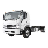
Isuzu FVR Commercial Truck Manuals
Manuals and User Guides for Isuzu FVR Commercial Truck. We have
4
Isuzu FVR Commercial Truck manuals available for free PDF download: Service Manual, Manual, Owner's And Driver's Manual
Isuzu FVR Service Manual (816 pages)
COMMERCIAL TRUCK Equipped with 6 HK1 engine
Brand:
Isuzu
| Category:
Trucks
| Size: 39 MB
Table of Contents
Cautions and Notices
14
Table of Contents
18
General Information
18
How to Use
21
Transmission Identification
25
Rear Axle Identification
26
Metric Fasteners
35
Maintenance and Lubrication
50
Specifications
50
Approximate Fluid
50
Fluid and Lubricant Recommendations
51
Maintenance Schedule
60
General Information
65
Inspections and Other Services
67
Vibration Diagnosis and Correction
69
Diagnostic Information and Procedures
69
Systematic Approach
69
Vibration Diagnosis
69
Classifying the Vibration Test
73
Tire and Wheel Vibration
76
Tire and Wheel Runout Measurement
76
Driveline Vibration Analysis with
80
Engine Related Vibration
84
Repair Instructions
88
General Service Precautions
88
Balancing Tires and Wheels
88
Wheel Weight Usage
92
Correcting Non-Uniform Tires
92
Correcting Driveline Vibration
93
RWD and 4WD
93
Description and Operation
111
General Description
111
Special Tools and Equipment
122
Heating and Ventilation (Non-A/C
126
Specifications
126
Fastener Tightening Specifications
126
Schematic and Routing Diagrams
126
Heater Blower Controls Schematic
126
Heater Blower Controls Schematics
127
HVAC Mode
128
Component Locator
129
Heater Blower
129
Heater Blower Controls Component
129
Heater Blower Controls
129
HVAC System
132
End Views
135
Diagnostic Information and Procedures
137
Blower Motor Inoperative at
137
Blower Motor Inoperative at Medium Speed
138
Blower Motor Inoperative at Low Speed Only
140
Heating Insufficient
140
Poor Ventilation
141
Heat Excessive
141
Repair Instructions
142
Control Assembly Replacement
142
Blower Switch
143
Blower Motor Resistor Replacement
144
Air Distributor Duct Replacement (Lower)
150
Air Distributor Duct
150
Air Inlet Actuator
151
Temperature Actuator Replacement
156
Mode Actuator Replacement
160
Heater Pipes
164
Heater Pipes Replacement (Outlet)
166
Heater Core Replacement (Right)
168
Heater Core Replacement (Left)
170
Heater System
175
Air Distribution System
176
HVAC Systems with A/C Manual
180
Specifications
180
Fastener Tightening Specifications
180
Compressor Specifications
180
Refrigerant Oil Distribution Specifications
181
Schematic and Routing Diagrams
181
HVAC Schematic References
181
HVAC Schematic
181
Icons
181
HVAC Blower Control Schematics
182
Component Locator
188
HVAC Components
188
HVAC Component Views
188
HVAC Connector End
188
Diagnostic Information and Procedures
201
Functional Check
201
HVAC Blower Controls System Check
201
HVAC Compressor Clutch Does Not Engage
202
HVAC Compressor Clutch Does Not Disengage
205
Blower Motor Inoperative at any
206
Blower Motor Low Speed Inoperative
206
Blower Motor Medium Speed Inoperative
207
Blower Motor Low and Medium Speeds Inoperative
208
Blower Motor High Speed Inoperative
208
Condenser Fan Inoperative
209
Condenser Fan on at All Times
210
System Performance Chart
211
Refrigerant System Checks
212
Leak Testing
213
Heat Excessive
216
Cooling Insufficient
216
Air Delivery
217
Repair Instructions
217
Odor Correction
217
Refrigerant Recovery
218
Compressor Replacement
219
Compressor Sealing Washers Replacement
222
0-Ring Replacement
224
Clutch Assembly
225
Compressor Magnetic Clutch (Disassembly)
228
Compressor Magnetic Clutch
228
Compressor Magnetic Clutch (A/C Compressor Seal)
228
Compressor Overhaul
231
Compressor Hose Assembly Replacement
231
Evaporator Hose Assembly Replacement
234
Receiver Dehydrator and Evaporator Hose Assembly
238
Receiver Dehydrator Replacement
240
Thermal Expansion Valve Replacement
242
A/C Temperature Sensor Replacement
245
Condenser Fan Replacement
247
Condenser Replacement
247
Blower Motor and Fan Replacement
254
HVAC Module Assembly Replacement
257
Evaporator Core Replacement
258
Heater Core Replacement (Right)
262
Heater Core Replacement
262
Heater Pipes Replacement
266
Heater Pipes Replacement (Outlet)
267
Passenger Compartment Air Replacement
268
Passenger Compartment Air Filter
268
Control Assembly Replacement
269
Blower Switch Replacement
270
Replacement
272
Replacement
275
Air Distributor Duct Replacement (Lower)
285
Air Distributor Duct Replacement
285
Description and Operation
287
System Description
288
Refrigeration System Description
288
Speed
290
Refrigeration System Description
290
Maintaining Chemical Stability
293
Evaporator Description
293
Condenser Description
294
Accumulator Description
294
Compressor Description
294
Ventilation Description
295
Relays and Sensors Description
295
HVAC Compressor Controls Circuit Description
297
Equipment
299
And Recharging
300
Body and Accessories
302
Lighting Systems
308
Specifications
308
Schematic and Routing Diagrams
308
Systems
320
Component Locator
320
Lighting Systems Components
320
Lighting Systems Component Views
320
Left Rear View
324
Visual Identification
344
Lighting Systems Connector End Views
344
Cigar Lighter
345
Diagnostic Information and Procedures
351
DRL System
351
Exterior Lights System
351
Backup Lights System Check
351
Interior Lights System Check
351
Interior Lights Dimming System Check
351
Backup Lamps Inoperative
352
Clearance Lamps Inoperative
353
Courtesy or Dome Lamps Inoperative
354
DRL Headlamps Always on
354
DRL Indicator Inoperative
354
Open
355
Hazard Lamps Inoperative
356
Headlamps Inoperative
357
Headlamps Inoperative
358
(DRL Off)
360
Headlamps Inoperative
360
Headlamp Switch off
361
Low Beams
361
Headlamps Inoperative Right High Beam (Headlamp)
363
Headlamps Inoperative Flash
363
High Beams
363
(Right)
364
Headlamps, DRL on with Engine Not Running
365
Instrument Panel Lamps Inoperative
366
(Dimming Lamps Inoperative)
367
Instrument Panel Lamps Inoperative
367
License and Tail Lamps Inoperative
368
Park Lamps Inoperative
369
Park Lamp Inoperative LF
370
Park Lamp Inoperative RF
370
Park, Side, and Front Marker Lamps Inoperative
371
Park, Side Marker, and Clearance Lamps Always on
371
Park, Side Marker, and Clearance Lamps Inoperative
372
Rearview Mirror Lamps Inoperative
373
Outside (both Mirrors)
373
Rearview Mirror Lamps Inoperative
374
Outside (Left Mirror)
374
Side Marker Lamp Inoperative
374
One Lamp (Left)
374
Side Marker Lamp Inoperative
375
One Lamp (Right)
375
Side Marker Lamps Inoperative
376
Headlamp Aiming
394
Park/Turn Signal Lamp Replacemen (Housing)
395
Clearance Lamp Replacement (Lamp Housing)
395
Clearance Lamp Replacement Outside Mirror (Housing)
400
Description and Operation
401
DRL Circuit Description
401
Backup Lights Circuit Description
402
Special Tools and Equipment
403
Wipers/Washer Systems
404
Schematic and Routing Diagrams
404
Wiper/Washer System Schematic References
404
Wiper/Washer System (Pulse)
406
Component Locator
406
Wiper/Washer System Components
406
Wiper/Washer System Component Views
407
Visual Identification
409
Wiper/Washer System Connector End Views
409
Diagnostic Information and Procedures
410
Wiper/Washer Diagnostic System Check
410
Wipers All Modes and Washer Inoperative
410
Wipers All Modes Inoperative
411
Wipers High Mode Inoperative, Low Mode Operates
412
Wipers Low Mode Inoperative, High Mode Operates
412
Wipers Always on
413
Washers Inoperative
414
Washers Always on
414
Wiper Arm Tip Pressure Check, Blade Element Check
415
Repair Instructions
415
Washer Pump/Reservoir Replacement
415
Arm Replacement
415
Wiper/Washer System
415
Body and Accessories
432
Speaker Noise
432
Antenna Diagnostic Check
434
(Left Front Speaker)
435
Speakers Inoperative One
436
Repair Instructions
438
Radio Replacement
438
Cassette Cleaning
439
Speaker Replacement
441
Description and Operation
442
Radio/Audio System Description
442
Radio/Audio System Operation
442
Circuit Description
443
Wiring Systems
444
Specifications
444
Fastener Tightening Specifications
444
Diagnostic Information and Procedures
444
How to Use Connector End
450
How to Use Diagnostic
450
Electrical Symbols
452
Strategy Based Diagnostic Flow
461
High Beams
462
Symptom Diagnostic Example
462
Troubleshooting with
463
Test Light
463
Troubleshooting with
464
Digital Multimeter
464
Using Connector Test Adapters
464
Testing for Continuity
465
Splicing Inline Harness
473
Connector Repairs
474
Connector Position
475
Terminal Position Assurance Locks
475
Schematic and Routing Diagrams
476
Power and Grounding Schematic References
476
Lamp
486
Fuse Block Details Schematics
486
Ground Distribution Schematics
492
Component Locator
505
Power and Grounding Components
505
Power and Grounding Component Views
519
Diagnostic Information and Procedures
528
Data Link Connector End Views
528
Data Link Connector
528
Components (EBCM (Hydraulic))
528
Description and Operation
530
Data Link Connector Description
530
Data Link Connector Operation
530
Data Link Connector Circuit
530
Inline Harness Connector End Views
531
Harness Routing
559
Icons
584
Instrument Panel, Gauges and Console
584
Specifications
584
Fastener Tightening Specifications
584
Schematic and Routing Diagrams
584
Instrument Cluster Schematic References
584
Instrument Cluster Schematic Icons
584
Component Locator
592
Instrument Panel
592
Instrument Cluster Components
592
Instrument Cluster Component Views
593
Visual Identification
604
Instrument Cluster Connector End Views
604
Fuel Transfer Pump
605
Diagnostic Information and Procedures
610
Gauge Engine Coolant Temp Always Cold
610
Gauge Eng Coolant Temp Inaccurate or Inoperative
612
Gauge Engine Oil Pressure Always High
613
Gauge Engine Oil Pressure
613
Gauge
614
Always Indicates Empty
615
Tanks)
615
Gauges Inoperative
622
All
622
Gauge Voltmeter Inaccurate or Inoperative
623
Indicator Check Gauge Always on (Cell 41)
624
Indicator Check Gauge Inoperative
624
Indicator Fasten Safety Belt Always on
625
Indicator Fasten Safety Belt
625
Inoperative
625
Indicator Low Engine Coolant Always on
626
Inoperative (Cell 41)
626
Indicator Low Engine Coolant Inoperative (Cell 81)
627
Speedometer Inaccurate (J 38522 Unavailable)
628
Speedometer And/Or Odometer Inoperative
628
Tachometer Inoperative
629
Schematic and Routing Diagrams
629
Audible Warnings Schematic References
629
Diagnostic Information and Procedures
631
Audible Warnings Components
631
Audible Warnings Component Views
631
Audible Warnings Connector End Views
634
Audible Warnings Diagnostic System Check
635
Chime Always
635
Chime Inoperative
636
Repair Instructions
638
IP Cluster Replacement (Instrument Cluster)
638
IP Cluster Replacement (Speedometer)
639
Cigar Lighter Replacement
640
Engine Oil Pressure Switch Replacement
640
IP Carrier Replacement
641
Multifunction Alarm Module Replacement
646
Description and Operation
647
Instrument Cluster Circuit Description
647
Audible Warnings Operation
648
Audible Warnings Circuit Description
651
Horns
652
Specifications
652
Fastener Tightening Specifications
652
Schematic and Routing Diagrams
652
Horns Schematic References
652
Horns Schematics
653
Component Locator
654
Horns Components
654
Horns Component Views
654
Horns Connector End Views
658
Diagnostic Information and Procedures
658
Horns Inoperative (One Does Not Sound)
659
Horns Always on
659
Repair Instructions
660
Horn Replacement (Single)
660
Horn Replacement (Dual)
661
Description and Operation
661
Horns Circuit Description
661
Exterior Trim
662
Repair Instructions
662
Emblem/Nameplate
662
Washing and Foreign Material Deposit Removal
663
Washing and Waxing
663
Cleaning Bright Metal
663
Waterleak Test
664
Repair Instructions
664
Generalized Testing
664
Diagnostic Information and Procedures
664
Water Hose Test
665
Air Hose Test
665
Stationary Window Waterleak Repair
665
Stationary Windows
666
Repair Instructions
666
Windshield Upper Reveal
666
Replacement
666
Windshield Replacement
667
Quarter Window Replacement
669
Rear Window Replacement
670
Window Polishing
672
Special Tools and Equipment
673
Bumpers
674
Specifications
674
Fastener Tightening
674
Repair Instructions
674
Bumper Replacement
674
Body Front End
678
Specifications
678
Fastener Tightening Specifications
678
Repair Instructions
679
Hood Replacement
679
Hood Latch
679
Fender Replacement
682
Battery Box
684
Component Box Replacement
685
Cab Replacement
686
Cab Lock Replacement
689
Cab Tilt Support Replacement
692
Step and Support Replacement
693
Fender Extension Bracket
695
Air Scoop Replacement
696
Panel Replacement Front
697
Splash Shield Replacement
697
Wheelhouse Panel Replacement
699
Wheelhouse Panel Replacement (Upper)
699
Specifications
700
Component Locator
703
Power Door Systems Components
703
Power Door Systems Component Views
703
Mirror)
705
Power Door Systems Connector
707
Power Window Switch
707
Power Windows System Check
708
Heated Mirror System Check
708
Power Window Inoperative RF
709
Power Windows Inoperative from LF Switch
710
Heated Mirrors Inoperative (Switch Indicator)
712
Heated Mirrors Inoperative
712
Heated Mirrors Inoperative
713
Heated Mirrors Always on
713
Repair Instructions
714
Trim Panel Replacement
714
Door Replacement
715
Door Handle Replacement
716
Lock Replacement
719
(Right Side)
719
Striker Replacement
721
Window Regulator Replacement (Left Side)
723
Window Handle Replacement
723
Window Replacement
724
Window Run Channel
725
Window Replacement Inner
726
Window Replacement Outer
727
Mirror Replacement
728
Description and Operation
730
Heated Mirror Circuit Description
730
Special Tools and Equipment
731
Specifications
732
Fastener Tightening Specifications
732
Diagnostic Information and Procedures
732
Seat Manual Adjuster Does
732
Lock
732
Repair Instructions
733
Seat Replacement
733
Seat Replacement
734
Seat Riser Replacement (Passenger)
735
Seat Riser Replacement (Driver)
739
Repair Instructions
742
Mat/Carpet Replacement
742
Trim Panel Replacement
743
Area Rear
743
Door Sill Plate Replacement
743
Headliner Replacement
744
Upper
744
Console Replacement
745
Center
746
Side Door
748
Cleaning Glass Surfaces
752
Trim
752
Seat Belt Care
753
Paint/Coatings
756
Specifications
756
Clearcoat Repair Specifications
756
3M Products
756
Clearcoat Repair Specifications
757
Meguiar Products
757
Anti-Corrosion Treatment and Repair
758
Paint Identification
760
Repair Instructions
761
Clearcoat Repair W/O Repainting
761
Corrosion Repair
762
Environmental Fallout (Acid Rain)
762
Paint Gauges
763
Clearcoat Thickness
763
Damage Repair
763
Specifications
764
Fastener Tightening Specifications
764
Electrode
764
Plug Weld Chart
765
Diagnostic Information and Procedures
765
Checking Frame Alignment
765
Frame
766
Frame Conditions
767
Repair Instructions
768
Straightening Description
768
Frame Repair
769
Crossmember Replacement
774
Installation Procedure
774
Body Mount Replacement (Cab Mounts)
774
Body Mount Replacement (Cab Mount)
778
Body Mount Replacement (Bracket)
780
Tow Hook Replacement
781
Assist Step and Support Replacement Lower
782
Description and Operation
784
Frame and Underbody Description
784
Minimizing Frame Service Description
785
Metals
786
Repair Instructions
786
Seat Belts
790
Specifications
790
Diagnostic Information and Procedures
790
Operational and Functional Checks
790
Repair Instructions
790
Seat Belt Service Precautions
790
Driver or Passenger Seat Belt Replacement
791
Center Seat Belt Fleplacement
798
Description and Operation
799
Seat Belt System Operation
799
Advertisement
Isuzu FVR Manual (808 pages)
Brand:
Isuzu
| Category:
Utility Vehicle
| Size: 45 MB
Table of Contents
Table of Contents
7
Pictorial Index
8
Vehicle Information
29
Important Information
37
Doors, Windows and Seats
134
Controls and Instruments
231
Comfort and Convenience
345
Comfort and Convenience Features
353
Tips on Safe and Smooth Operation
422
Service and Maintenance
425
In Case of Emergency
683
Main Data
763
Isuzu FVR Manual (472 pages)
Brand:
Isuzu
| Category:
Utility Vehicle
| Size: 25 MB
Table of Contents
Table of Contents
7
Pictorial Index
8
Vehicle Information
21
Important Information
27
Doors, Windows and Seats
100
Controls and Instruments
105
Comfort and Convenience
161
Comfort and Convenience Features
191
Tips on Safe and Smooth Operation
233
Service and Maintenance
235
In Case of Emergency
403
Main Data
447
Advertisement
Isuzu FVR Owner's And Driver's Manual (203 pages)
Heavy Commercial Vehicles
Brand:
Isuzu
| Category:
Utility Vehicle
| Size: 10 MB
Table of Contents
Optional Device
5
Table of Contents
6
Important Information
11
VIN Number and Engine Number
11
Overloading
12
Operation of New Vehicle
13
Uses and Precautions of New Vehicle
15
Services and Maintenance
16
Switches and Instruments
17
Steering Wheel Control
18
Starter Switch
19
Adjustment Steps
19
Light Control Switch
20
Exhaust Brake Switch
22
Instrument Cluster
24
Instruments and Indicators
27
Instrument Cluster
27
Indicator Lamps
28
Fuel Gauge
30
High Beam Indicator Lamp
34
Accelerator Pedal
39
Brake Pedal
39
Other Instructions
40
Cigarette Lighter
44
Cab Tilting
53
Fuel Tank Filler Cap
56
Before Driving Your Vehicle
58
Operation Control
58
Driver's Seat
60
Passenger Seat
60
Interior Rearview Mirror
65
Driver Checklist (Daily Check)
66
After Starting the Engine
74
Driving
77
Preparations before Starting the Engine
77
Engine Start
78
Stopping of the Engine
80
Operation of Turbocharged Engine
80
Before Driving off
81
Parking
82
Driving Precautions
82
Driving for Economy
86
Precautions about Driving in Winter
87
Driving on Snowy or Frozen Roads
89
Precautions for Vehicle Use in Tropical Area
90
In Case of an Emergency
91
Emergency Starting
92
Tire Replacement
99
Long Term Storage
102
Maintenance Schedule
103
Maintenance Operations
103
Services and Maintenance
103
Lubrication Schedule
113
Maintenance Guide
115
Coolant Level
116
Fuel Pump
125
Valve Clearance Adjustment
127
Clutch Pedal Adjustment
131
Replacing Light Bulbs
137
Lubricating Oil
145
Transmission Oil Replacement
155
Parts for Grease Filling
157
Special Equipment Operation
164
Electronic Tuning am Radio with Clock
164
Scan Button
166
Cassette Player with Electronically Tuned Radio and Clock
168
Volume Control Knob
169
Loading Limit
174
Loading Method
181
Main Data and Specifications
185
Additional Descriptions
203
Advertisement
Related Products
Isuzu FVM
Isuzu FVZ
Isuzu FVR33G
Isuzu FVR34J
Isuzu FVZ34K
Isuzu FVZ34N
Isuzu FVZ34V
Isuzu FSS
Isuzu FTS
Isuzu F Series
Isuzu Categories
Engine
Automobile
Utility Vehicle
Trucks
Control Systems
More Isuzu Manuals
Login
Sign In
OR
Sign in with Facebook
Sign in with Google
Upload manual
Upload from disk
Upload from URL