Sign In
Upload
Manuals
Brands
Intel Manuals
Server Board
S5000XAL
Intel S5000XAL Manuals
Manuals and User Guides for Intel S5000XAL. We have
4
Intel S5000XAL manuals available for free PDF download: Technical Product Specification, Specification, Tested Hardware And Operating System List
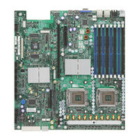
Intel S5000XAL Technical Product Specification (113 pages)
Intel Server Board Technical Product Specification
Brand:
Intel
| Category:
Server Board
| Size: 2.99 MB
Table of Contents
Revision History
2
Table of Contents
4
1 Introduction
11
Chapter Outline
11
Server Board Use Disclaimer
11
2 Product Overview
12
Intel Server Board S5000PAL / S5000XAL Feature Set
12
Server Board Layout
13
Connector and Component Locations
14
Figure 1. Components & Connector Location Diagram
15
Light Guided Diagnostic LED Locations
16
Figure 2. Light Guided Diagnostic LED Location Diagram
16
External I/O Connector Locations
17
Figure 3. Intel Server Board S5000PAL / S5000XAL ATX I/O Layout
17
Server Board Mechanical Drawings
18
Figure 5. Intel ® Server Board S5000PAL / S5000XAL - Hole and Component Positions (2
19
Figure 7. Intel ® Server Board S5000PAL / S5000XAL - Restricted Areas on Side 2
21
3 Functional Architecture
23
Figure 9. Server Board Functional Block Diagram
23
Intel ® 5000P and 5000X Memory Controller Hubs (MCH)
24
System Bus Interface
24
Processor Support
24
Table 1. Processor Support Matrix
25
Memory Sub-System
26
Figure 10. CEK Processor Mounting
26
Figure 11. Memory Layout
26
Table 2. I 2 C Addresses for Memory Module SMB
27
Table 3. Maximum 8 DIMM System Memory Configuration - X8 Single Rank
27
Table 4. Maximum 8 DIMM System Memory Configuration - X4 Dual Rank
27
Figure 12. Recommended Minimum Two DIMM Memory Configuration
29
Figure 13. Recommended Four DIMM Configuration
30
Figure 14. Single Branch Mode Sparing DIMM Configuration
31
Snoop Filter (5000X MCH Only)
32
ESB-2 IO Controller
32
PCI Sub-System
33
Table 5. PCI Bus Segment Characteristics
33
Serial ATA Support
35
Parallel ATA (PATA) Support
36
USB 2.0 Support
36
Video Support
36
Table 6. Video Modes
37
Network Interface Controller (NIC)
38
Intel ® I/O Acceleration Technology
38
MAC Address Definition
38
Table 7. NIC2 Status LED
38
Super I/O
39
Table 8. Serial a Header Pin-Out
39
Figure 15. Serial Port Configuration Jumper Location
40
Table 9. Rear Serial B Port Adapter Pin-Out
40
4 Platform Management
42
Figure 16. SMBUS Block Diagram
42
5 Connector / Header Locations and Pin-Outs
43
Board Connector Information
43
Table 10. Board Connector Matrix
43
Power Connectors
44
Table 11. Power Connector Pin-Out (J3K3)
44
Table 12. 12V Power Connector Pin-Out (J3K4)
44
Table 13. Power Supply Signal Connector Pin-Out (J1K1)
44
System Management Headers
45
Intel ® Remote Management Module (RMM) Connector
45
Table 14. Intel ® RMM Connector Pin-Out (J1C5)
45
Intel ® RMM NIC Connector
46
Table 15. 30-Pin Intel ® RMM NIC Module Connector Pin-Out (J1B2)
46
LCP/AUX IPMB Header
47
IPMB Header
47
Riser Card Slots
47
Table 16. LPC/AUX IPMB Header Pin-Out (J1C2)
47
Table 17. IPMB Header Pin-Out (J1C3)
47
Table 18. Low-Profile Riser Slot Pin-Out (J5B1)
47
Table 19. Full-Height Riser Slot Pin-Out (J4F1)
48
SSI Control Panel Connector
52
Bridge Board Connector
52
Table 20. Front Panel SSI Standard 24-Pin Connector Pin-Out (J3H2)
52
Table 21. 120-Pin Bridgeboard Connector Pin-Out (J4G1)
52
I/O Connector Pin-Out Definition
54
VGA Connector
54
NIC Connectors
54
Table 22. VGA Connector Pin-Out (J6A1)
54
Table 23. RJ-45 10/100/1000 NIC Connector Pin-Out (JA8A1, JA8A2)
54
IDE Connector
55
Intel ® I/O Expansion Module Connector
55
Table 24. 44-Pin IDE Connector Pin-Out (J3G1)
55
SATA Connectors
56
Table 25. 50-Pin Intel ® I/O Expansion Module Connector Pin-Out (J3B1)
56
Table 26. SATA Connector Pin-Out (J1H1, J1G2, J1G1, J1F2, J1E3)
56
Serial Port Connectors
57
Keyboard and Mouse Connector
57
Table 27. External RJ-45 Serial 'B' Port Pin-Out (J9A2)
57
Table 28. Internal 9-Pin Serial 'A' Header Pin-Out (J1B1)
57
Table 29. Stacked PS/2 Keyboard and Mouse Port Pin-Out (J9A1)
57
USB 2.0 Connectors
58
Table 30. External USB Connector Pin-Out (J5A1, J6A2)
58
Table 31. Internal USB Connector Pin-Out (J1J1)
58
Fan Headers
59
Table 32. SSI Fan Connector Pin-Out (J9K1,J5K1,J3K1,J3K2,J7A2,J7A1)
59
6 Jumper Block Settings
60
Recovery Jumper Blocks
60
Figure 17. Recovery Jumper Blocks (J1D1, J1D2, J1D3)
60
Table 33. Recovery Jumpers (J1D1, J1D2, J1D3)
60
BMC Force Update Procedure
61
CMOS Clear and Password Reset Usage Procedure
61
BIOS Select Jumper
62
Figure 18. BIOS Select Jumper (J3H1)
62
External RJ45 Serial Port Jumper Block
63
Figure 19. External RJ45 Serial Port Configuration Jumper
63
7 Light Guided Diagnostics
64
5-Volt Standby LED
64
Figure 20. 5V Standby Status LED Location
64
System ID LED and System Status LED
65
Figure 21. System ID LED and System Status LED Locations
65
System Status LED - BMC Initialization
66
DIMM Fault Leds
67
Processor Fault LED
67
Figure 22. DIMM Fault LED Locations
67
Figure 23. Processor Fault LED Location
67
Post Code Diagnostic Leds
68
Figure 24. POST Code Diagnostic LED Location
68
8 Power and Environmental Specifications
69
Intel Server Board S5000PAL / S5000XAL Design Specifications
69
Table 34: Server Board Design Specifications
69
Server Board Power Requirements
70
Processor Power Support
70
Figure 25. Power Distribution Block Diagram
70
Table 35. Dual-Core Intel ® Xeon ® Processor 5000 Sequence TDP Guidelines Per Processor
70
Power Supply Output Requirements
71
8.2.3 Turn on no Load Operation
71
Table 36. 600W Load Ratings
71
Table 37: no Load Operating Range
71
Grounding
72
Standby Outputs
72
Remote Sense
72
Voltage Regulation
72
Table 38. Voltage Regulation Limits
72
Dynamic Loading
73
Capacitive Loading
73
Closed-Loop Stability
73
Common Mode Noise
73
Table 39. Transient Load Requirements
73
Table 40. Capacitive Loading Conditions
73
Ripple / Noise
74
Soft Starting
74
Timing Requirements
74
Table 41. Ripple and Noise
74
Figure 26. Output Voltage Timing
75
Table 42. Output Voltage Timing
75
Figure 27. Turn On/Off Timing (Power Supply Signals)
76
Table 43. Turn On/Off Timing
76
Residual Voltage Immunity in Standby Mode
77
9 Regulatory and Certification Information
78
9.1 Product Regulatory Compliance
78
Product Safety & Electromagnetic (EMC) Compliance
78
Electromagnetic Compatibility Notices
79
FCC Verification Statement (USA)
79
ICES-003 (Canada)
79
Europe (CE Declaration of Conformity)
79
BSMI (Taiwan)
80
RRL (Korea)
80
Product Ecology Compliance
81
Other Markings
82
Appendix A: Integration and Usage Tips
83
Appendix B: BMC Sensor Tables
84
Table 44. BMC Sensors
86
Appendix C: POST Code Diagnostic LED Decoder
100
Figure 28. Diagnostic LED Placement Diagram
100
Table 45: POST Progress Code LED Example
100
Table 46. Diagnostic LED POST Code Decoder
101
Appendix D: POST Error Messages and Handling
104
Table 47. POST Error Messages and Handling
104
Table 48. POST Error Beep Codes
106
Table 49. BMC Beep Codes
106
Appendix E: Supported Intel Server Chassis
107
Figure 29. 1U - Intel Server Chassis SR1500 Overview
107
Figure 30. 1U - Intel ® Server Chassis SR1550 Overview
108
Figure 31. 2U - Intel ® Server Chassis SR2500 Overview
109
Glossary
110
Reference Documents
113
Advertisement
Intel S5000XAL Specification (112 pages)
Product Specification
Brand:
Intel
| Category:
Server Board
| Size: 2.98 MB
Table of Contents
Revision History
2
Table of Contents
4
1 Introduction
11
Chapter Outline
11
Server Board Use Disclaimer
11
2 Product Overview
12
Intel® Server Board S5000PAL / S5000XAL Feature Set
12
Server Board Layout
13
Connector and Component Locations
14
Figure 1. Components & Connector Location Diagram
15
Light Guided Diagnostic LED Locations
16
Figure 2. Light Guided Diagnostic LED Location Diagram
16
External I/O Connector Locations
17
Figure 3. Intel® Server Board S5000PAL / S5000XAL ATX I/O Layout
17
Server Board Mechanical Drawings
18
Figure 4. Intel® Server Board S5000PAL / S5000XAL - Hole and Component Positions (1
18
Figure 5. Intel® Server Board S5000PAL / S5000XAL - Hole and Component Positions (2
19
Figure 6. Intel® Server Board S5000PAL / S5000XAL - Restricted Areas on Side 1
20
Figure 7. Intel® Server Board S5000PAL / S5000XAL - Restricted Areas on Side 2
21
3 Functional Architecture
23
Figure 9. Server Board Functional Block Diagram
23
Intel ® 5000P and 5000X Memory Controller Hubs (MCH)
24
System Bus Interface
24
Processor Support
24
Memory Sub-System
25
Figure 10. CEK Processor Mounting
25
Figure 11. Memory Layout
26
Table 1. I C Addresses for Memory Module SMB
26
Table 2. Maximum 8 DIMM System Memory Configuration - X8 Single Rank
27
Table 3. Maximum 8 DIMM System Memory Configuration - X4 Dual Rank
27
Figure 12. Recommended Minimum Two DIMM Memory Configuration
28
Figure 13. Recommended Four DIMM Configuration
29
Figure 14. Single Branch Mode Sparing DIMM Configuration
30
Snoop Filter (5000X MCH Only)
31
ESB-2 IO Controller
31
PCI Sub-System
32
Table 4. PCI Bus Segment Characteristics
32
Serial ATA Support
34
Parallel ATA (PATA) Support
35
USB 2.0 Support
35
Video Support
35
Table 5. Video Modes
36
Network Interface Controller (NIC)
37
Intel ® I/O Acceleration Technology
37
MAC Address Definition
37
Table 6. NIC2 Status LED
37
Super I/O
38
Table 7. Serial a Header Pin-Out
38
Figure 15. Serial Port Configuration Jumper Location
39
Table 8. Rear Serial B Port Adapter Pin-Out
39
4 Platform Management
41
Figure 16. SMBUS Block Diagram
41
5 Connector / Header Locations and Pin-Outs
42
Board Connector Information
42
Table 9. Board Connector Matrix
42
Power Connectors
43
Table 10. Power Connector Pin-Out (J3K3)
43
Table 11. 12V Power Connector Pin-Out (J3K4)
43
Table 12. Power Supply Signal Connector Pin-Out (J1K1)
43
System Management Headers
44
Intel ® Remote Management Module (RMM) Connector
44
Table 13. Intel ® RMM Connector Pin-Out (J1C5)
44
Intel ® RMM NIC Connector
45
Table 14. 30-Pin Intel ® RMM NIC Module Connector Pin-Out (J1B2)
45
LCP/AUX IPMB Header
46
IPMB Header
46
Riser Card Slots
46
Table 15. LPC/AUX IPMB Header Pin-Out (J1C2)
46
Table 16. IPMB Header Pin-Out (J1C3)
46
Table 17. Low-Profile Riser Slot Pin-Out (J5B1)
46
Table 18. Full-Height Riser Slot Pin-Out (J4F1)
47
SSI Control Panel Connector
51
Bridge Board Connector
51
Table 19. Front Panel SSI Standard 24-Pin Connector Pin-Out (J3H2)
51
Table 20. 120-Pin Bridgeboard Connector Pin-Out (J4G1)
51
I/O Connector Pin-Out Definition
53
VGA Connector
53
NIC Connectors
53
Table 21. VGA Connector Pin-Out (J6A1)
53
Table 22. RJ-45 10/100/1000 NIC Connector Pin-Out (JA8A1, JA8A2)
53
IDE Connector
54
Intel ® I/O Expansion Module Connector
54
Table 23. 44-Pin IDE Connector Pin-Out (J3G1)
54
SATA Connectors
55
Table 24. 50-Pin Intel ® I/O Expansion Module Connector Pin-Out (J3B1)
55
Table 25. SATA Connector Pin-Out (J1H1, J1G2, J1G1, J1F2, J1E3)
55
Serial Port Connectors
56
Keyboard and Mouse Connector
56
Table 26. External RJ-45 Serial 'B' Port Pin-Out (J9A2)
56
Table 27. Internal 9-Pin Serial 'A' Header Pin-Out (J1B1)
56
Table 28. Stacked PS/2 Keyboard and Mouse Port Pin-Out (J9A1)
56
USB 2.0 Connectors
57
Table 29. External USB Connector Pin-Out (J5A1, J6A2)
57
Table 30. Internal USB Connector Pin-Out (J1J1)
57
Fan Headers
58
Table 31. SSI Fan Connector Pin-Out (J9K1,J5K1,J3K1,J3K2,J7A2,J7A1)
58
6 Jumper Block Settings
59
Recovery Jumper Blocks
59
Figure 17. Recovery Jumper Blocks (J1D1, J1D2, J1D3)
59
Table 32. Recovery Jumpers (J1D1, J1D2, J1D3)
59
BMC Force Update Procedure
60
CMOS Clear and Password Reset Usage Procedure
60
BIOS Select Jumper
61
Figure 18. BIOS Select Jumper (J3H1)
61
External RJ45 Serial Port Jumper Block
62
Figure 19. External RJ45 Serial Port Configuration Jumper
62
7 Light Guided Diagnostics
63
5-Volt Standby LED
63
Figure 20. 5V Standby Status LED Location
63
System ID LED and System Status LED
64
Figure 21. System ID LED and System Status LED Locations
64
System Status LED - BMC Initialization
65
DIMM Fault Leds
66
Processor Fault LED
66
Figure 22. DIMM Fault LED Locations
66
Figure 23. Processor Fault LED Location
66
Post Code Diagnostic Leds
67
Figure 24. POST Code Diagnostic LED Location
67
8 Power and Environmental Specifications
68
Intel® Server Board S5000PAL / S5000XAL Design Specifications
68
Table 33: Server Board Design Specifications
68
Server Board Power Requirements
69
Processor Power Support
69
Figure 25. Power Distribution Block Diagram
69
Table 34. Dual-Core Intel ® Xeon ® Processor 5000 Sequence TDP Guidelines Per Processor
69
Power Supply Output Requirements
70
8.2.3 Turn on no Load Operation
70
Table 35. 600W Load Ratings
70
Table 36: no Load Operating Range
70
Grounding
71
Standby Outputs
71
Remote Sense
71
Voltage Regulation
71
Table 37. Voltage Regulation Limits
71
Dynamic Loading
72
Capacitive Loading
72
Closed-Loop Stability
72
Common Mode Noise
72
Table 38. Transient Load Requirements
72
Table 39. Capacitive Loading Conditions
72
Ripple / Noise
73
Soft Starting
73
Timing Requirements
73
Table 40. Ripple and Noise
73
Figure 26. Output Voltage Timing
74
Table 41. Output Voltage Timing
74
Figure 27. Turn On/Off Timing (Power Supply Signals)
75
Table 42. Turn On/Off Timing
75
Residual Voltage Immunity in Standby Mode
76
9 Regulatory and Certification Information
77
9.1 Product Regulatory Compliance
77
Product Safety & Electromagnetic (EMC) Compliance
77
Electromagnetic Compatibility Notices
78
FCC Verification Statement (USA)
78
ICES-003 (Canada)
78
Europe (CE Declaration of Conformity)
78
BSMI (Taiwan)
79
RRL (Korea)
79
Product Ecology Compliance
80
Other Markings
81
Appendix A: Integration and Usage Tips
82
Appendix B: BMC Sensor Tables
83
Table 43. BMC Sensors
85
Appendix C: POST Code Diagnostic LED Decoder
99
Figure 28. Diagnostic LED Placement Diagram
99
Table 44: POST Progress Code LED Example
99
Table 45. Diagnostic LED POST Code Decoder
100
Appendix D: POST Error Messages and Handling
103
Table 46. POST Error Messages and Handling
103
Table 47. POST Error Beep Codes
105
Table 48. BMC Beep Codes
105
Appendix E: Supported Intel Server Chassis
106
Figure 29. 1U - Intel ® Server Chassis SR1500 Overview
106
Figure 30. 1U - Intel ® Server Chassis SR1550 Overview
107
Figure 31. 2U - Intel ® Server Chassis SR2500 Overview
108
Glossary
109
Reference Documents
112
Intel S5000XAL Specification (42 pages)
Specification Update
Brand:
Intel
| Category:
Motherboard
| Size: 0.69 MB
Table of Contents
Revision History
2
Table of Contents
4
Preface
7
Summary Tables of Changes
8
Errata
11
IPMI over Serial Direct Connect Not Supported
11
Serial over LAN and IPMI over LAN Connections May Terminate Unexpectedly under Certain Conditions
11
Intermittent Beep Code 1-5-2-1 When Booting with Two Processors
11
Power Supply Population Errors May Not Display in the SEL
11
Fan 5 May Report a Reading of 0 RPM after the BMC Is Updated
12
The BMC May Not Respond to the IPMI Command, Send Message Sent Via LAN
12
Fans May Take a Long Time to Slow down after Fan Boosting
13
System Requires ~35 Seconds after AC Power Is Applied before the Power Button Responds
13
SEL Events for Hot-Swap Controller (HSC) May Appear after a DC Cycle
13
Fans May Run Faster than Expected after Exiting BIOS Setup
13
System Fault LED May Report Incorrect Status for some Events
14
Fan Removal Does Not Generate a SEL Event
14
Power Supply Redundancy State Is Misleading When Only One Power Supply Is Installed
15
Hot-Swap Controller (HSC) and Local Control Panel (LCP) Updates May Take a Long Time
15
Console Redirection Baud Rate Setting Auto Changing to 19.2K with Serial over LAN (SOL) Active
15
Serial over LAN (SOL) Unable to Redirect DOS Output
16
Password on Boot Not Supported
16
Intel® Embedded Server RAID Technology II Option Is Not Enabled in Initial BIOS
16
Release
16
HSC and BMC Versions Intermittently Not Seen in BIOS Setup
16
Intel® Server Boards S5000PAL/S5000XAL and Intel® Server System SR1500AL
17
Testing
17
Show a "Changes in Hardware or Drivers Detected" Error Message During WHQL ACPI Stress Testing
17
POST Leds Do Not Turn off after Operating System Loads
17
Checkup7.Exe (Microcode Update Utility) Is Not Storing Microcode in BIOS
18
Intel® RAID Controller SRCSAS144E Causes Systems to Reset Multiple Times before Completing POST
18
Change Logo Utility Does Not Save Modified BIOS Capsule Files with Correct Extension
19
PS/2 Keyboards and Mice May Stop Functioning after Red Hat* Enterprise Linux Is Installed
19
Failures Seen Installing to a SATA Drive When SATA Is Set to "Legacy" in the BIOS
20
Setup
20
System Hangs after Disabling On-Board Video in the BIOS Setup
20
The SMBIOS Entry Point May Not be Visible under Certain Hardware Configurations14
20
Suse* Linux Enterprise Server May Not Install Successfully with Intel® Embedded Server RAID Technology II Enabled
21
Red Hat* Enterprise Linux 4 and BIOS Setup Display a Different L2 Cache Size for the Quad-Core Intel® Xeon® Processor 5300 Series
22
Change Logo Utility Causes BIOS Corruption
22
Microsoft Windows System Event Viewer* May Record Error Event with ID 11
22
After the System Reboots, the POST Screen May Generate "NMI Has Been Received - System Halted" Message
23
Intel® RAID Web Console 2 Utility Displays "Unexpected Sensor" Warning Message in Microsoft Windows* Operating System
23
Random Drives May Go Offline When a Sixth Drive Is Installed and Intel® Embedded Server RAID Technology II Is Enabled in the Intel® Server System SR2500ALBRP
24
Dual Gigabit Expansion Module May Not Properly Reset
24
SAS Drive in a ROMB RAID 5 May Drop Offline During a Reboot in the Intel® Server System SR2500PALLX
25
Intel® Server System SR2500ALLX Sixth Hard Drive Filler Panel Is Difficult to
25
Remove
25
Suse* Linux Enterprise Server Unable to Boot after Basic Installation
26
Drives May Not be Detected or May Go Offline in the Intel® Server System SR2500ALBRP When Operating at SATA 3Gb/S Data Rate
26
New Versions of BMC Firmware with Previous Versions of BIOS Cause System POST Failure
27
Intel® Server System SR2500ALLX May Operate Louder than Expected
27
Red Hat* Enterprise Linux May Report the Wrong Processor Speed
27
The Suse* Linux Enterprise Server 10 Driver for SAS HW RAID Causes Unwanted Error Logs During Installation
27
IERR or Thermal Trip Event Reported in System Event Log (SEL) after System Power on
28
USB Device Generates "The Following Boot-Start or System-Start Driver(S) Failed to Load: I8042Prt" Error Message in Microsoft Windows* Operating Systems
29
Microsoft Windows* and Intel® RAID Web Console II Report an Error When the ASR2500SATAPE Kit Is Used
29
System May Log Ierrs When Running Certain Red Hat* Enterprise Linux Versions on the Intel® Server Board S5000PAL with Video Driver Ati_Drv.o 6.5.6
29
Microsoft Windows* Operating Systems Installed Without a Service Pack will Display Blue Screen with BIOS 79 and 81
30
Sluggish System Performance May be Experienced with BMC 60
31
Downgrading the Firmware of the Integrated RAID (ROMB), Intel® Embedded Server RAID Technology II, or SAS May Cause System Damage
31
In the Intel® Server Systems SR2500ALLX and SR1550ALSAS, Flashing of SAS
31
During SAS Controller Scanning
31
Firmware 1.22 and SAS BIOS 06.16.00 Makes Hard Drive #1 (Upper Left Drive Tray) Undetected During SAS Controller Scanning
31
Microsoft Windows 2003 R2 SP2* May Display Blue Screen During an Operating System Boot or Shutdown with a Specific Version of Intel I/OAT Driver
32
Server System Event Log (SEL) Time May be One Day Later than BIOS Time after Entering Year 2008
33
Performance Power Management Error in Microsoft Windows Server 2008
33
Midplane2 Hardware RAID Produces Unexpected Beep Sounds During System POST
34
Platform Confidence Test (PCT) Fails with BIOS 89/91 on Intel® Server Board S5000PAL/S5000XAL
34
USB Mouse May Hang in BIOS 94 RAID Console
34
PCI IBIST Error with BIOS 84
35
System May Hang During Login or Shutdown
35
Hard Disks Are Difficult to Install in Intel® Server System SR2500AL and Intel® Server Chassis SR2500
35
System will Not Skip CD/DVD Drive with BIOS Revision R0098 When RMM2 Installed
36
Please Use AXXMINIDIMM512 as the Replacement Solution for AXXMINIDIMM Which Is Eoled
37
Minus "Year" Number to Go Past "2000" at BIOS "System Date" Set up Interface will Cause the Server System to Hang
37
Please Do Not Downgrade BIOS from Factory Shipped BIOS 101 to any Previous Version
37
The Serial Port Console Redirection Displays the Adaptec® 5805 RAID
38
Documentation Changes
39
The SMBUS Block Diagram (Figure #16) Provided in Rev. 1.1 of the Intel Server Board S5000PAL/S5000XAL TPS Requires Changes to Accurately Reflect Production Hardware Design
39
The Power Block Diagram (Figure #25) as Provided in Rev. 1.1 of the Intel Server Board S5000PAL/S5000XAL TPS Does Not Reflect the Final, Production-Level Baseboard Design
40
SAS/SAS RAID Midplane Board (Figure #22) as Provided in Rev.1.0 of the Intel
41
Front Panel Pin-Out in the Intel
42
Advertisement
Intel S5000XAL Tested Hardware And Operating System List (38 pages)
Hardware Guide
Brand:
Intel
| Category:
Server Board
| Size: 0.19 MB
Table of Contents
Revision History
3
Table of Contents
5
1 Introduction
7
Test Overview
7
Basic Installation Testing
7
Adapter/Peripheral Compatibility and Stress Testing
8
Pass/Fail Test Criteria
9
2 Intel Server Board S5000PAL/S5000XAL Base System Configurations
10
3 Supported Operating Systems
12
Operating System Certifications
15
4 Adapters and Peripherals
17
Pci Nic
19
Pci Sw Raid Sata
21
Pci Sw Raid Scsi
22
Pci Sw Raid Sas
23
PCI Fiber Channel
24
Video
26
Pci Hw Raid Sas
26
Pci Hw Raid Sata
29
Pci Hw Raid Scsi
33
CD-ROM Drives
33
DVD Drives
34
Tape Drives
35
Input
35
Removable Media
36
Other
37
5 Hard Disk Drives
38
Advertisement
Related Products
Intel S5000XSL
Intel S5000XVNSAS - Boxed Workstn Board Integrate 4PORTSAS
Intel S5000PSLSATA
Intel S5000PSLSATAR - Inte Dual LGA771
Intel S5000VCL - Server Board Motherboard
Intel S5000VSA4DIMMR - Xeon 50XX 51XX 53XX 54XX 4 FBDIMM Slots 6 SATA Port Motherboard
Intel S5000VSASATA
Intel S5000VSASATAR
Intel S5000VSASCSI - Mother Bd 0 No Cpu
Intel S5000XVNSASR
Intel Categories
Motherboard
Computer Hardware
Server
Server Board
Desktop
More Intel Manuals
Login
Sign In
OR
Sign in with Facebook
Sign in with Google
Upload manual
Upload from disk
Upload from URL