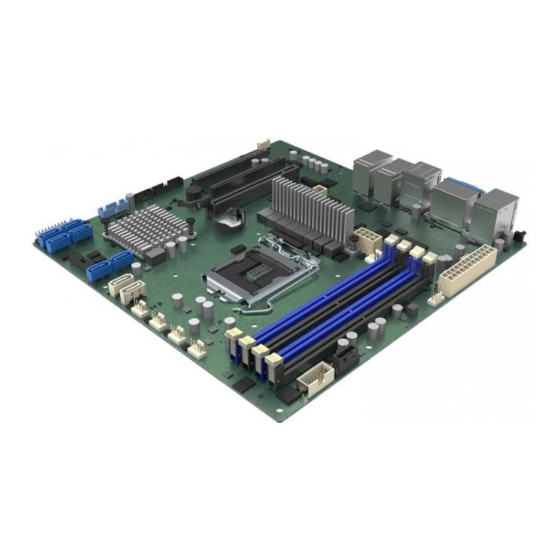
Sign In
Upload
Manuals
Brands
Intel Manuals
Server Board
M10JNP2SB
Intel M10JNP2SB Manuals
Manuals and User Guides for Intel M10JNP2SB. We have
1
Intel M10JNP2SB manual available for free PDF download: User Manual
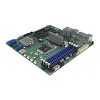
Intel M10JNP2SB User Manual (75 pages)
Brand:
Intel
| Category:
Server Board
| Size: 3.4 MB
Table of Contents
Table of Contents
6
1 Introduction
10
Intel Server Board Use Disclaimer
10
2 Server Board Overview
11
Server Board Features Overview
11
Figure 1. Intel® Server Board M10JNP2SB
11
Table 1. Intel® Server Board M10JNP2SB Features/Specifications
11
Server Board Component / Feature Identification
13
Figure 2. Server Board Component / Feature Identification
13
Server Board Mechanical Drawings
14
Figure 3. Server Board Mounting Holes
14
Figure 4. Component Height Restrictions
15
Figure 5. Major Components and Connectors 1 of 2
16
Figure 6. Major Components and Connectors 2 of 2
17
Product Architecture Overview
18
Figure 7. Intel® Server Board M10JNP2SB Block Diagram
18
3 Processor Support
19
Table 2. Intel® Xeon® E-2200 Processor Family Features List
19
Table 3. Intel® Xeon® E-2100 Processor Family Features List
19
Processor Features
20
4 Memory Support
21
Supported Memory
21
Figure 8. Memory Subsystem Architecture
21
Figure 9. DIMM Slot Identification
21
General Memory Population Rules
22
Memory RAS Features
22
Table 4. DIMM Population Recommendations
22
Table 5. Memory RAS Features
22
5 Server Board I/O
23
Pcie Add-In Card Support
23
Pcie* Enumeration and Allocation
23
Figure 10. Pcie Slot Identification
23
One-Slot Pcie Riser Card Option (Ipc - JNP1URISER)
24
Networking
24
Figure 11. 1U One-Slot Pcie* Riser Card Option (Ipc - Jnp1Uriser)
24
Figure 12. Rear Networking Ports
24
Table 6. One-Slot Pcie* Riser Card Slot Description
24
Usb
25
External USB 3.1 Connectors
25
Front Panel USB 3.1 Connector
25
Figure 13. External USB 3.1 Gen2 Ports
25
Table 7. 10/100/1000 Mbps LAN Link/Activity LED Matrix
25
Onboard SATA Support
26
SATADOM Support
26
Figure 14. Front Panel USB 3.0 Connector
26
Figure 15. SATADOM Connector Pinout
26
6 Server Management
27
Shared Management Interface
27
Embedded Web Server
27
Figure 16. BMC Embedded Web Server User Interface
28
7 On-Board Connector/Header Pin-Out Overview
29
Power Connectors
29
Table 8 PWR1 Pin-Out
29
Table 9. PWR2 Pin-Out
29
Onboard Storage Connectors
30
SATA 6 Gbps Connectors
30
SATADOM 6 Gbps Connectors
30
SATA SGPIO Connector
30
Table 10. SATA Connector Pin-Out
30
Table 11. SATADOM Connector Pin-Out
30
Table 12. SGPIO Connector Pin-Out
30
Fan Connectors
31
System Fan Connectors
31
Processor Fan Connectors
31
Front Panel Headers and Connectors
31
Front Panel Header
31
Front Panel USB 3.1 Connector
31
Table 13. System Fan Connector Pin-Out
31
Table 14. Processor Fan Connector Pin-Out
31
Table 15. Front Panel Header Pin-Out
31
Table 16. Front Panel USB 3.1 Connector Pinout
31
Dedicated LAN Activity LED Headers
32
Other Headers and Connectors
32
Serial Port Connectors
32
Table 17. LAN 3 Activity LED Header
32
Table 18. LAN 4 Activity LED Header
32
Table 19. TPM Header Pin-Out
32
Table 20. COM1 Port Pin-Out
32
Power Supply Monitoring Interface (PSMI) Connector
33
IPMB Header
33
Chassis Intrusion Header
33
ID LED Header
33
Table 21. COM2 Port Pin-Out
33
Table 22. PSMI Connector Pin-Out
33
Table 23. IPMB Header Pin-Out
33
Table 24. Chassis Intrusion Header Pin-Out
33
Table 25. ID LED Header Pin-Out
33
8 Reset and Recovery Jumpers
34
Clear CMOS Jumper Block
34
Figure 17. Board Jumper Identification
34
BIOS Recovery Jumper
35
9 Server Board and Essential System Component Installation and Removal
36
Figure 18. Server Board Mounting Hole Location
36
Before You Begin
36
Installing the Server Board
37
Server Board Removal
37
Figure 19. Removing the Socket Protection Cap
38
Figure 20. Opening the Socket Lever
38
Installing the Processor
38
Figure 21. Opening the Processor Load Plate
39
Figure 22. Installing the Processor
39
Figure 23. Closing the Load Plate
40
Figure 24. Closing the Socket Lever
40
Figure 25. Installing the Heat Sink
41
Figure 26. Connecting the Fan Cable
41
Processor Heat Sink Installation
41
Figure 27. Removing the Fan Cable
42
Figure 28. Removing the Heat Sink
42
Heat Sink Removal
42
Figure 29. DIMM Installation
43
Figure 30. DIMM Removal
43
Memory (DIMM) Installation
43
Memory (DIMM) Removal
43
Removing the Processor
43
Connecting SATA Drives
44
Figure 31. Attaching SATA Cables
44
Figure 32. Removing SATA Cables
44
Removing SATA Drives
44
Connecting System Fans
45
Figure 33. System Fan Connector Identification
45
Figure 34. Connecting System Fan Cables
45
Disconnecting System Fans
46
Figure 35. Removing System Fan Cables
46
Appendix A. Usage Tips
47
Appendix B. Getting Help
48
Appendix C. POST Code Errors
49
Table 26. PEI Phase
50
Appendix D. Additional References
58
Appendix E. Safety Instructions
59
Appendix F. Safety and Regulatory Certifications
69
Table 27. Product Safety Compliance
69
Table 28. Product EMC Compliance
69
Table 29. Product Regulatory Compliance Markings
70
Table 30. Product Regulatory Compliance
71
Appendix G. Statement of Volatility
72
Table 31. Server Board Components
73
Glossary
74
Advertisement
Advertisement
Related Products
Intel M1920
Intel MB899
Intel NetStructure MPCBL0001
Intel EtherExpress PRO/100 MBLA1600
Intel Motherboard
Intel MB896
Intel M50CYP1UR Series
Intel MX4305UE
Intel MB966-NB
Intel MCS 51
Intel Categories
Motherboard
Computer Hardware
Server
Server Board
Desktop
More Intel Manuals
Login
Sign In
OR
Sign in with Facebook
Sign in with Google
Upload manual
Upload from disk
Upload from URL