Sign In
Upload
Manuals
Brands
Intel Manuals
Server
E80367-001
Intel E80367-001 Manuals
Manuals and User Guides for Intel E80367-001. We have
1
Intel E80367-001 manual available for free PDF download: Product Specification
Intel E80367-001 Product Specification (71 pages)
Server System
Brand:
Intel
| Category:
Server
| Size: 3 MB
Table of Contents
Table of Contents
4
Introduction
11
Server Board Use Disclaimer
11
Product Overview
12
Table 1. System Feature Set
12
System Views
14
System Dimensions
14
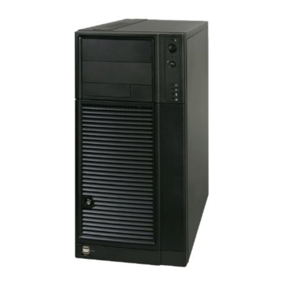
Figure 1. Intel ® Server System SC5650BCDP
14
Table 2. Intel ® Server System SC5650BCDP Dimensions
14
System Components
15
Figure 2. Intel ® Server System SC5650BCDP Components
15
Table 3. Intel ® Server System SC5650BCDP Components Reference
15
I/O Panel
16
Rack and Cabinet Mounting Option
16
Front Bezel Features
16
Server Board Overview
16
Figure 3. ATX 2.2 I/O Aperture
16
Figure 4. Intel ® Server Board S5500BC Picture
17
Server Board Connector and Component Layout
18
Figure 5. Intel ® Server Board S5500BC Layout
18
Table 4. Board Layout Reference
18
Intel ® Light-Guided Diagnostic LED Locations
19
Figure 6. Intel ® Light-Guided Diagnostic LED Locations
19
Table 5. Intel ® Light-Guided Diagnostic LED Reference
20
Power Sub-System
21
600-Watt Power Supply
21
Mechanical Overview
22
Figure 7. Mechanical Drawing for Power Supply Enclosure
22
Airflow and Temperature
23
Output Cable Harness
23
Table 6. Thermal Environmental Requirements
23
Figure 8. Output Cable Harness for 600-W Power Supply
24
Table 7. Cable Lengths
25
Table 8. P1 Baseboard Power Connector
25
Table 9. P2 Processor 0 Power Connector
26
Table 10. P3 Processor 1 Power Connector
26
Table 11. P4 Power Signal Connectors
26
Table 12. P5-P8 Peripheral Power Connector
26
AC Input Requirements
27
Table 13. P9 Right-Angle SATA Power Connector
27
Table 14. P10 SATA Power Connector
27
Table 15. AC Input Rating
28
Table 16. AC Line Sag Transient Performance
29
Table 17. AC Line Surge Transient Performance
29
DC Output Specifications
30
Table 18. Load Ratings
31
Table 19. Voltage Regulation Limits
32
Table 20. Transient Load Requirements
32
Table 21. Capacitive Loading Conditions
33
Table 22. Ripple and Noise
34
Table 23. Output Voltage Timing
34
Figure 9. Output Voltage Timing
35
Table 24. Turn on / off Timing
35
Protection Circuits
36
Current Limit (OCP)
36
Figure 10. Turn On/Off Timing (Power Supply Signals)
36
Table 25. over Current Protection (OCP)
37
Table 26. over Voltage Protection Limits
37
Figure 11. PSON# Required Signal Characteristics
38
Table 27. PSON# Signal Characteristics
38
Table 28. PWOK Signal Characteristics
38
FRU Data
39
Cooling Sub-System
40
Fan Configuration
40
Server Board Fan Control
40
Cooling Solution
40
System Fan Connectors
41
Figure 12. Cooling Fan Configuration for Intel ® Server Board S5500BC
41
Table 29. CPU and System Fan Connector Pin-Out
42
Peripheral and Hard Drive Support
43
In Peripheral Drive Bay
43
In Peripheral Drive Bays
43
Figure 13: Front View Components (Without Front Bezel Assembly)
43
Table 30: Front View Components Reference
43
Hot Swap Hard Disk Drive Bays
44
Fixed Hard Drive Bay
44
Figure 14: Fixed Hard Drive Bay
45
Standard Control Panel
46
Control Panel
46
Figure 15. Panel Controls and Indicators
46
Table 31. Control Panel LED Functions
47
PCI Cards and Assembly
48
Environmental and Regulatory Specifications
49
System Level Environmental Limits
49
Serviceability and Availability
49
Table 32. System Environmental Limits Summary
49
Replacing the CMOS Battery
50
Table 33. System Maintenance Procedure Times
50
Product Regulatory Compliance
51
Use of Specified Regulated Components
51
Table 34. Product Safety & Electromagnetic (EMC) Compliance
52
Electromagnetic Compatibility Notices
54
Usa
54
FCC Verification Statement
55
ICES-003 (Canada)
55
Europe (CE Declaration of Conformity)
55
Japan EMC Compatibility
55
BSMI (Taiwan)
56
RRL (Korea)
56
CNCA (CCC-China)
56
Product Ecology Compliance
56
Table 35. Product Ecology Compliance Reference Table
57
Other Markings
59
Appendix A: Integration and Usage Tips
60
Appendix B: POST Code Diagnostic LED Decoder
61
Figure 16. Diagnostic LED Placement Diagram
61
Table 36. POST Progress Code LED Example
61
Table 37. Diagnostic LED POST Code Decoder
62
Appendix C: POST Error Messages and Handling
65
Table 38. SEL Format for POST Error Messages
65
Table 39. POST Error Messages and Handling
65
Table 40. POST Error Beep Codes
68
Glossary
70
Reference Documents
71
Advertisement
Advertisement
Related Products
Intel CORE 2 DUO PROCESSOR E8000 -
Intel E810 VDA4T Series
Intel E810-XXVDA4T
Intel E810-CQDA2T
Intel EE110TX24
Intel Xeon E5310
Intel Express 10/100 Stackable Hub Ethernet Module
Intel Intel E7501 MCH
Intel E7000 Series
Intel Embedded Server RAID Technology 2
Intel Categories
Motherboard
Computer Hardware
Server
Server Board
Desktop
More Intel Manuals
Login
Sign In
OR
Sign in with Facebook
Sign in with Google
Upload manual
Upload from disk
Upload from URL