Sign In
Upload
Manuals
Brands
Inovance Manuals
Controller
MD500T45GB-INT
Inovance MD500T45GB-INT Drive Controller Manuals
Manuals and User Guides for Inovance MD500T45GB-INT Drive Controller. We have
1
Inovance MD500T45GB-INT Drive Controller manual available for free PDF download: User Manual
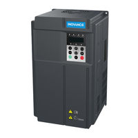
Inovance MD500T45GB-INT User Manual (341 pages)
High Performance
Brand:
Inovance
| Category:
Controller
| Size: 28 MB
Table of Contents
Please Read this Important Information
2
Table of Contents
3
Safety Information and Precautions
5
Electrical Installation - Safety
6
Working Environment and Handling
6
AC Motor (Induction/Asynchronous)
7
Adjusting AC Drive Parameters
7
Product Information
8
Product Type Identification
9
Chapter 1 Product Information
9
Internal View of MD500
10
Ratings
12
Technical Specifications
13
Mechanical Installation
18
Installation Environment
19
Chapter 2 Mechanical Installation
19
Mounting Orientation and Clearance
20
Installation of an Air Guide Plate
21
Mounting Dimensions
22
Installation Method and Procedures
23
Backplate Mounting
23
Backplate-Mounted Installation of a Plastic Housing
24
Backplate-Mounted Installation of a Sheet Metal Housing
24
Through Hole Mounting
25
Preparing the Backplate for Hole Cut-Out
26
Installing the AC Drive into the Hole Cut-Out
26
Remove and Refit the Front Cover
28
Electrical Installation
30
Typical System Connection
31
Chapter 3 Electrical Installation
31
Main Circuit Wiring
32
Main Circuit Terminals
32
Cable Dimensions and Tightening Torque
33
Crimp Terminal Recommendation
37
Main Circuit Cable Recommendations
39
Main Circuit Cable Selection
39
Power Input
39
DC Bus Terminals
40
Braking Resistor
40
AC Drive Outputs U, V, W to Motor
40
Cable Support Bracket Models
41
Grounding (PE) Connection
42
Main Circuit Cable Protection
43
Power Input Protection
43
Power Grid System
43
Control Circuit Wiring
44
Terminal Arrangement
44
Terminal Function
45
Wiring Diagrams
47
Selection of Control Circuit Wirings
47
Cabling Requirements
47
Wiring of AI1
48
Wiring of AI2
48
Wiring of DI1 to DI5
49
Source Wiring
50
Wiring of DI5 (High-Speed Pulse Input)
50
Wiring of DO
51
Wiring of High-Speed Output FM
51
Wiring of Relay
52
Wire Size and Torque Specification
52
Wiring Checklist
53
Operating Panel
54
Keypad and Display
55
Inbuilt LED Operating Panel
55
Chapter 4 Operating Panel (Keypad & Display)
55
Introduction
55
Keys on LED Operating Panel
56
Relevant Parameters for Operating Panel Setting
57
Status Indicators
57
Unit Indicators
58
LED Display
58
LED Operating Panel Menu Structure
59
Unmodifiable Parameters
61
Overall Arrangement of Function Parameters
62
Selection of Function Parameter Group
62
Selection of Displaying a and U Groups
62
Function Parameter Operations
63
Viewing Function Parameters
63
Editing Function Parameters
64
MF.K Key Function
65
Saving and Restoring Settings
65
Password Security
66
Quick Setup
68
Operating Panel View
69
Chapter 5 Quick Setup
69
Get Familiar with Operating Panel
69
Setup Flowchart
70
Description of Parameters
82
Start/Stop Command Source
83
Chapter 6 Description of Parameters
83
Terminal I/O Control
84
Serial Communication
90
Set Frequency Reference
91
Select Main Frequency Reference Setting Channel
92
Select a Required Curve for AI Terminal
97
Pulse Reference (DI5)
99
Multi-Reference
100
Simple PLC
101
PID Reference
104
Serial Comms.
110
Setting Auxiliary Frequency Reference
112
Main & Auxiliary Calculation
114
Command Source + Frequency Reference Setting Channel
116
Frequency Reference Limit
117
Running Mode When Frequency Reference below Lower Limit
117
Start Mode
118
Start/Stop the AC Drive
118
Stop Mode
121
Acceleration/Deceleration Time and S-Curve Setting
123
Motor Auto-Tuning
125
Control Performance
129
V/F Curve
129
V/F Separation Curve
131
Current Limit Control
132
Torque Boost
132
Voltage Limit and Braking Unit Applied Voltage
134
Speed Loop
135
SVC/FVC Slip Compensation Gain
135
SVC Speed Feedback Stability
136
Setting Torque Limit in Torque Control
138
Auxiliary Control
139
Current Loop
139
Improving Field Weakening Area Performance
139
Motor Overload Protection
140
Protections
140
Phase Loss Protection
141
Fault Protection Action Selection
142
Fault Reset
142
Motor Overheat Protection
144
Power Dip Ride-Through
144
Load Lost Protection
145
Overspeed Protection
146
Speed Error Protection
146
Undervoltage & Overvoltage Threshold and Overcurrent Fast Prevention
146
Output Overcurrent Protection
147
Monitoring
148
View Parameters in Group U0
150
Process Control
155
The Wobble Function
155
Fixed Length Control
156
Counting
157
Motor 2 Parameters
159
User Programmable Card
160
Parameter Settings of Controlling MD500 by PLC Programming Function
162
Master and Slave Control
165
Droop Control
171
Control Circuit Terminals
173
Function of DI Terminals
173
Function of DO Terminals
177
Function of VDI Terminals
180
Function of VDO Terminals
181
Function of the AI Terminals
182
Function of the AO and Pulse Output Terminals
183
Communication
185
Read and Write Function Parameters
185
Read and Write State Parameters
187
Write RUN Command
189
Write Frequency/Torque Reference
191
Control of Analog and High-Speed Pulse Output (AO, FMR)
192
Control of Digital Output (DO, Relay, FMR)
192
Parameter Initialization
192
Auxiliary Function
193
Jog
193
FWD/REV Switchover Dead-Zone Time, Reverse Run Prohibited
194
Jump Frequency
194
Frequency Detection (FDT)
196
Frequency Reference Reached Detection Width
196
Acceleration/Deceleration Time Switchover
197
Frequency Reached Detection
198
Zero Current Detection
198
Current Detection
199
Timing Function
199
AI1 Input Voltage Upper/Lower Limit
200
Cooling Fan
200
Hibernating and Wakeup
200
Module Temperature
200
Deceleration Time for Emergency Stop
201
Output Power Correction
201
Running Time Threshold this Time
201
Interfaces and Communication
202
About Use of MD500 Terminals
203
Filter Time and Delay Functions
203
Use of DI Terminals
203
Use of DO Terminals
203
Chapter 7 Interfaces and Communication
203
Use of AI Terminals
204
Use of AO Terminals
204
Use of PG Terminal
205
Serial Communication
206
About Multi-Functional Extension Interfaces
207
Definition of Communication Data Address
208
Parameter Data
208
Non-Parameter Data
209
Bus Structure
211
Modbus Communication Protocol
211
Data Format
212
CRC Check
214
Definition of Communication Parameter Addresses
215
Stop/Run Parameters
216
Group Fd Communication Parameter Description
218
Peripherals and Options
220
Chapter 8 Peripherals and Options
221
Description of Peripheral Electrical Devices
223
MCCB, Fuse and Contactor
224
Braking Unit and Braking Resistor
225
Mounting Dimensions of MDBUN Series Braking Unit
227
Mounting Dimensions of Energy Feedback Unit
228
Mounting Dimensions of MDBU Series Braking Unit
228
External Operating Panel
229
Extension Cards
230
Functional Extension Cards
232
Extension Communication Cards
239
Extension PG Cards
249
Through-Hole Mounting Bracket
257
Emc
261
Chapter 9 Technical Data
261
Installing Fuse on the Input Side
262
Definition of Terms
263
Selection of Peripheral EMC Devices
263
Simple EMC Filter
268
Safety Capacitance Box and Ferrite Core
269
AC Input Reactor Installation
270
AC Output Reactor Installation
272
DV/Dt Reactor Installation
276
Common-Mode Filter
278
Breaker & Fuse Selection
279
Shielded Cable
279
Solutions to Current Leakage
280
Solutions to Common EMC Interference Problems
281
De-Rating
282
Maintenance and Inspection
284
Daily Inspection
285
Chapter 10 Maintenance and Inspection
285
Periodic Inspection Items
287
Insulation Test on Main Circuit
288
Replacement of Wearing Components
289
Removing and Installing the Fan of a Plastic Housing
290
Removing and Installing the Fan of a Sheet Metal Housing
291
Storage
292
Warranty Agreement
292
Troubleshooting
294
Chapter 11 Troubleshooting
295
Safety Information
295
Troubleshooting During Trial Run
296
Fault Display
298
Resetting Fault
298
Faults and Diagnostics
299
Symptoms and Diagnostics
306
Appendix A Parameter Table
309
Introduction
309
Standard Parameters
310
Monitoring Function Codes
332
Index
334
Advertisement
Advertisement
Related Products
Inovance MD500T18.5GB-INT
Inovance MD500T37GB-INT
Inovance MD500T55GB-INT
Inovance MD500T75GB-INT
Inovance MD500T90G-INT
Inovance MD500T110G-INT
Inovance MD500T132G-INT
Inovance MD500T160G-INT
Inovance MD500T22GB-INT
Inovance MD500T30GB-INT
Inovance Categories
Servo Drives
DC Drives
Controller
Control Unit
Inverter
More Inovance Manuals
Login
Sign In
OR
Sign in with Facebook
Sign in with Google
Upload manual
Upload from disk
Upload from URL