Sign In
Upload
Manuals
Brands
Innovative Technology Manuals
Industrial Equipment
PureLab HE Glovebox
Innovative Technology PureLab HE Glovebox Manuals
Manuals and User Guides for Innovative Technology PureLab HE Glovebox. We have
1
Innovative Technology PureLab HE Glovebox manual available for free PDF download: User Manual
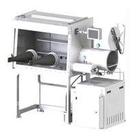
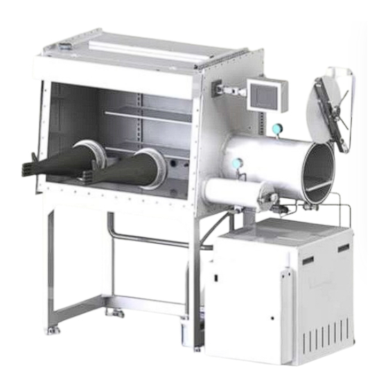
Innovative Technology PureLab HE Glovebox User Manual (80 pages)
Brand:
Innovative Technology
| Category:
Industrial Equipment
| Size: 1 MB
Table of Contents
Table of Contents
3
Figures
6
Tables
7
About this Manual
9
Firmware Revisions
9
Optional Equipment
9
Terms
9
Symbols Used
9
System Overview
10
Figure 1 Purelab HE Gas Purifier
11
The PLC Enclosure
12
Exterior Controls
12
Circuit Breakers
12
Foot Pedal
12
Installation
13
Pre-Installation Requirements
13
Working Gas
13
Regeneration Gas
13
Electrical
13
System Exhaust
13
Unpacking the System
14
Assembly
14
Figure 2 Assembled Glovebox
14
Electrical Connections
16
Gas Connections
16
Venting Connections
16
Commissioning the System
16
Switching Power on
17
Pressure Testing the System
17
Figure 3 Glovebox Control Screen
17
Adjusting the Box Pressures
18
Figure 4 Login/Logout Button
18
Figure 5 Main Glovebox Control Screen
18
Figure 6 Glovebox Config Screen
19
Figure 7 Numerical Input Screen
19
Purging
20
Circulation
21
Figure 8 Glove Box Control System
21
Figure 9 Bower Control Screen
21
Control Panel Functions
23
The Main Control Screen
23
Figure 10 Glove Box Control System
23
Initial Power on
24
Figure 11 Glovebox Powered on
24
Figure 12 Login/Logout Screen
24
Figure 13 Glove Box Control System with Fully Functional Buttons
25
Control Sub-Screens
26
Regen Control
26
Regen Timers
27
Figure 14 Regeneration Control Screen
27
Solvent Regen
28
Figure 15 Regen Timers Screen
28
Figure 16 Solvent Regeneration Control Screen
28
Solvent Regen Timers
29
Blower Control
29
Figure 17 Solvent Regen Screen
29
Purge Control
30
Figure 18 Blower Control Screen
30
Automatic Antechamber Control
31
Figure 19 Purge Control Screen
31
Antechamber Config
32
Figure 20 Antechamber Control Screen
32
Figure 21 Antechamber Config Screen
32
System Config
33
Figure 22 Glove Box Config Screen
33
Alarms
34
Figure 23 Alarms Screen
34
Freezer Control
35
Figure 24 Trend Screen
35
Figure 25 Freezer Control Screen
35
Box Cooling Control
36
Heater Control
36
Figure 26 Box Cooling Control Screen
36
Figure 27 Heater Control Screen
37
System Operation
38
Adjusting the System Pressure
38
Figure 28 Glove Box Config Screen
38
Figure 29 Numerical Input Screen
38
Using the Antechambers
39
Manual Antechamber Control
39
Figure 30 Large and Mini Antechambers
39
Removing an Item from the Glovebox Using the Large Antechamber
40
Mini Antechamber
40
Introducing an Item into the Glovebox Using the Mini Antechamber
40
Figure 31 Inside Antechambers
40
Removing an Item from the Glovebox Using the Mini Antechamber
41
Automatic Antechamber Control
41
Figure 32 Antechamber Control Screen
41
Introducing an Item into the Glovebox Using the Large Antechamber
42
Figure 33 Antechamber Config Screen
42
Figure 34 Inserting an Object into the Antechamber
43
Figure 35 Removing Object from Antechamber
43
Removing an Item from the Glovebox Using the Large Antechamber
44
Purge Valves
44
Figure 36 Hand-Operated 2-Way Ball Valve
44
Automatic Purge Valve
45
Figure 37 Automatic Purge Valve
45
Figure 38 Purge Control Screen
45
Regeneration
46
Figure 39 Regeneration Control Screen
46
Single-Column Purification System Regeneration Procedure
47
Figure 40 Regen Timers Screen
47
Dual-Column Purification System Regeneration Procedure
48
Solvent Regeneration
48
Solvent-Column System Regeneration Procedure
48
Figure 41 Glove Box Config Screen
48
Figure 42 Gas Purification Module
49
Figure 43 Solvent Regeneration Control Screen
49
Analyzers
50
O2 Analyzer
50
Moisture Analyzer
50
Freezers
51
Figure 44 Cylindrical & Rectangular Box Freezers
51
Figure 45 Freezer Control Screen
51
Box Cooling Control
52
Figure 46 Box Cooling
52
Figure 47 Box Cooking Control Screen
52
Heater Control
53
Parallel - Piped Systems
53
Figure 48 Heater Control Screen
53
Figure 49 Blower Control Screen
54
Solvent Removal Systems
55
Large Capacity Solvent Removal
55
Opening the Solvent Removal Column
55
Figure 50 Purge Control Screen
55
Isolating the Solvent Removal Column and Removing Solvent Vapors
56
Figure 51 Solvent Removal Column - Open
56
Replacing the Carbon Charge in a Solvent Removal Column
57
Large Capacity Regenerable Solvent Removal
58
Small Capacity Solvent Removal - External
58
Routine Maintenance
60
Daily Tasks
60
Weekly Tasks
60
Annual or Semi Annual Tasks
60
Safety Inspections
60
Troubleshooting
61
System Control Electronics
63
General Description
63
PLC Controller
63
Display Panel
63
Lower Control Box
63
Power Supply
63
Box Pressure Sensor
63
Volt Low Power Relays
63
Circuit Breakers
65
Specifications
65
System Components
67
Box Flow
67
Piping and Valves
67
Column
67
The Blower
68
Vacuum Pump
68
Chambers
68
Removal and Replacement Procedures
69
Blower
69
Column
69
Filters
70
Gloves
70
Replacing a Glove Increases the Risk of Exposing the System to the Outside Environment. Prior to Proceeding, Ensure that Every Precaution Is Taken to Protect the Contents of the Box
70
Replacement with an Internal Glove Port Cover
70
Replacement Without an Internal Glove Port Cover
71
Control Box Panel
71
Circuit Breakers
71
Power Supply
71
Solid State Relays
72
Valves
72
Vacuum Pump
72
Window
73
Spare Parts
73
System Diagrams
74
Front View
74
Back View
75
Pure Lab HE 2GB and Pure Lab HE 4GB-2500 Overall Dimensions
76
Pure Lab HE 3GB Overall Dimensions
78
Pure Lab HE 4GB-1800 Overall Dimensions
79
Pure Lab HE 4GB-1950 Overall Dimensions
80
Advertisement
Advertisement
Related Products
Innovative Technology PA00231
Innovative Technology PA00266
Innovative Technology PA00267
Innovative Technology PA01174
Innovative Technology Categories
Bank Note Validator
Turntable
Speakers
Stereo System
Docking Station
More Innovative Technology Manuals
Login
Sign In
OR
Sign in with Facebook
Sign in with Google
Upload manual
Upload from disk
Upload from URL