Table of Contents
Advertisement
Quick Links
Advertisement
Table of Contents

Summary of Contents for Innovative Technology PureLab HE Glovebox
- Page 1 PureLab HE Glovebox User Manual...
- Page 2 © Innovative Technology, Inc. 1994 - 2006 No part of this manual may be reproduced in any form, electrical or mechanical, including photocopy, recording, or any information storage and retrieval system, without permission in writing from Innovative Technology, Inc. Company Information Innovative Technology, Inc.
-
Page 3: Table Of Contents
System Config ......................33 4.3.10 Alarms........................34 4.3.11 Freezer Control ......................35 4.3.12 Box Cooling Control ....................36 4.3.13 Heater Control ......................36 5 System Operation ........................38 Adjusting the System Pressure ..................38 Innovative Technology, Inc. iii of 80... - Page 4 Circuit Breakers ......................65 Specifications ........................65 9 System Components ......................... 67 Box Flow ........................... 67 9.1.1 Piping and Valves ..................... 67 9.1.2 Column ........................67 9.1.3 The Blower ........................ 68 9.1.4 Vacuum Pump ......................68 iv of 80 Innovative Technology, Inc.
- Page 5 10.7.3 Pure Lab HE 2GB and Pure Lab HE 4GB-2500 Overall Dimensions ....... 76 10.7.4 Pure Lab HE 3GB Overall Dimensions ..............78 10.7.5 Pure Lab HE 4GB-1800 Overall Dimensions ............79 10.7.6 Pure Lab HE 4GB-1950 Overall Dimensions ............80 Innovative Technology, Inc. v of 80...
-
Page 6: Figures
Figure 47 Box Cooking Control screen ....................52 Figure 48 Heater Control screen ......................53 Figure 49 Blower Control screen ......................54 Figure 50 Purge Control screen ......................55 Figure 51 Solvent Removal Column - Open ..................56 vi of 80 Innovative Technology, Inc. -
Page 7: Tables
Figure 65 Pure Lab HE 4GB-1950 ......................80 Tables Table 1 Circuit Breakers ......................... 12 Table 2 Relay Functions and Connections..................... 64 Table 3 Solid State Relays ........................65 Table 4 Circuit Breakers ......................... 65 Table 5 Specifications ..........................65 Innovative Technology, Inc. vii of 80... -
Page 9: About This Manual
About This Manual This document explains how to install and operate your Glovebox system and accessories. References are made in the Installation section to features in the Operational section. It is imperative that you refer to them as indicated. If you have any further questions please call our offices at 978-462-4415 If the Glovebox system is modified or used in a manner not specified by the manufacturer, the protection provided by the equipment can be impaired. -
Page 10: System Overview
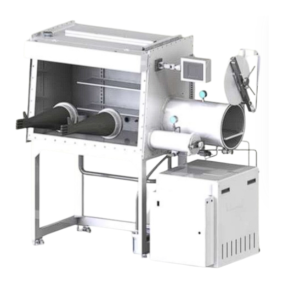
System Overview General Warning Symbol High Voltage Hazard Hot Surface Hazard System Overview PureLab HE is designed as a complete package including box, Antechamber(s), gas purification system and vacuum pump. The system is capable of removing O2 and H2O to levels less than 1 ppm. -
Page 11: Figure 1 Purelab He Gas Purifier
System Overview Figure 1 PureLab HE Gas Purifier The vacuum pump is located on the Glovebox stand, allowing for easy access and oil change. The Gas Purification system module has removable side panels and a top panel, allowing easy access to the Valve Assembly, Purifier Column, Valves, and Blower. In addition you will find: ... -
Page 12: The Plc Enclosure
System Overview 2.1 The PLC Enclosure The PLC enclosure is located on the front of the gas purification module. 2.2 Exterior Controls On the PLC enclosure, mounted on the side wall, you will find several circuit breakers and an illuminated main circuit breaker that doubles as the main power on switch. 2.3 Circuit Breakers There are eleven (11) circuit breakers on the side wall. -
Page 13: Installation
One cylinder of Nitrogen or Argon containing approximately 3 to 7% Hydrogen. 3.1.3 Electrical All Innovative Technology, Inc. Glovebox systems are configured to operate using the electrical power standard for the region in which the Glovebox has been ordered. The standard 2-glove system requires 2 electrical outlets, one for the main system power Note: and one for the power supplied to the power strip inside the Glovebox. -
Page 14: Unpacking The System
Installation 3.2 Unpacking the System All systems shipped outside North America are packaged in specially designed shipping crates. These systems require a forklift or similar lifting device to safely remove the Glovebox and Gas Purification module from the crate. For more information, please ask your Innovative Technology, Inc. - Page 15 Installation For double box systems, the two boxes need to be joined prior to performing the Note: following procedure. See the next procedure, “To assemble a double box system”. To install the Glovebox system See Glovebox layout drawing (Figure 1). The Glovebox system has lockable casters on each leg to facilitate its placement.
-
Page 16: Electrical Connections
1.25 turns from finger tight. Over tightening compression fittings can cause problems. If you are not familiar with compression fittings please call your Innovative Technology Note: representative for further assistance. -
Page 17: Switching Power On
Installation 3.7.1 Switching Power On The main power ON/OFF switch is accessible from the left side of the gas purifier module on the side wall of the PLC enclosure. Switch the power on. The main power switch light ups. All box electrical equipment is enabled with this switch. -
Page 18: Adjusting The Box Pressures
Installation Figure 4 Login/Logout button To Log in as a User, press the Login User button and then enter the code 7990. The Login User button turns Green and flashes Accepted. Press the Main Screen button to reach the Main Glovebox Control screen (Figure 5). Figure 5 Main Glovebox Control screen 3.7.3 Adjusting the Box Pressures... -
Page 19: Figure 6 Glovebox Config Screen
Installation Figure 6 Glovebox Config Screen Press the Numeric blue display button next to Working Maximum SP. A numerical input screen appears (Figure 7). Type in 12.0 and press the Enter key. Press the Numeric blue display button next to Working Minimum SP. A numerical input screen appears. -
Page 20: Purging
If the pressure drops more than 1 mbar, check all of the connections that were made during the assembly process. Contact your Innovative Technology, Inc. representative if you require assistance in troubleshooting. 3.7.4 Purging The purpose of purging the system is to displace the air in the box with the inert gas of your choice. -
Page 21: Circulation
Installation 3.7.5 Circulation The blower is designed to circulate the Glovebox atmosphere continuously through the purifier column. For optimum performance the blower must run constantly. Turning off the blower results in the atmosphere within the Glovebox degrading as it is not being circulated through the O2 and H2O absorbing materials contained within the purifier column. - Page 22 Installation The blower provided is continuously variable; it can be set at a very low speed if you are handling sensitive crystals or during weighing. It can be set at a maximum to recover quickly from an operator error. We suggest it be set at 50% during normal operation. Blower speed can be changed by pressing the numeric value next to the Change Blower Speed.
-
Page 23: Control Panel Functions
Control Panel Functions Control Panel Functions All Glovebox functions are controlled from the touch screen (HMI – Human Machine Interface). This section describes the touchscreen and all the functions associated with it. The HMI is typically located on the side panel that has the large Antechamber attached. Custom systems may have the HMI mounted in a different location. -
Page 24: Initial Power On
Control Panel Functions 4.2 Initial Power On When the system is powered on the following screen (Figure 11) appears: Figure 11 Glovebox powered on This screen indicates the basic status parameters but does not allow any interaction until the user logs in to the HMI. -
Page 25: Figure 13 Glove Box Control System With Fully Functional Buttons
Control Panel Functions Figure 13 Glove Box Control System with fully functional buttons : Depending on the particular configuration of your system not all buttons may be Note available. Pure_Lab_Manual Rev 6_4-14-2015.docx 25 of 80... -
Page 26: Control Sub-Screens
Control Panel Functions Box Pressure (mbar) The Main Control Screen continuously displays the current Glovebox pressure. This pressure is displayed in mbar relative to atmospheric pressure. The current pressure is displayed in the blue bar. For information on adjusting the box pressure, see “Commissioning the System”... -
Page 27: Regen Timers
Regen Timers Button Accesses sub-screen below. 4.3.2 Regen Timers The Regen timers are set in minutes. Below are the factory default settings (Figure 15). Do not change these timers without contacting your Innovative Technology service provider. Pure_Lab_Manual Rev 6_4-14-2015.docx 27 of 80... -
Page 28: Solvent Regen
Control Panel Functions Figure 15 Regen Timers screen Step 1: Heat Indicates duration of Heating Cycle in minutes. Step 2: Heat & Purge Indicates duration of Heat & Purge Cycle in minutes. Step 3: Purge Indicates duration of Purge Cycle in minutes. Step 4: Evacuate Indicates duration of Evacuate Cycle in minutes. -
Page 29: Solvent Regen Timers
Control Panel Functions Start Button Initiates a solvent regeneration. Are the Column Valves Prompts the user to CLOSE the manual isolation valves on Large Capacity Closed? Regenerable Solvent Removal Column. Is Flow OK? Prompts the user to acknowledge that the inert gas is flowing. Regen Status Indicates the current step in the regeneration cycle. -
Page 30: Purge Control
Control Panel Functions Figure 18 Blower Control screen The blower can be turned on or off from this screen as well as from the Main Screen. O2 Blower Speed Enabling this feature automatically adjusts the blower speed based on the oxygen level within the Glovebox. -
Page 31: Automatic Antechamber Control
Control Panel Functions Figure 19 Purge Control screen O2 Level Purge SP If the system is fitted with an oxygen analyzer this setting will open the (ppm) automatic purge valve if the oxygen level exceeds the set value. This value can be changed by pressing the value and entering the desired value on the numeric keypad. -
Page 32: Antechamber Config
Control Panel Functions Figure 20 Antechamber Control screen Use Antechamber Allows the user to select which Antechamber to control. This is only Number utilized if your system is configured with multiple automatic Antechambers. Current Cycle Indicates how many evacuate/refill cycles have already been completed. Pressure (mbar) Indicates the absolute pressure within the Antechamber as measured with the digital vacuum gauge. -
Page 33: System Config
Control Panel Functions Auto Evacuate SP The set point that the Antechamber will be evacuated to. (mbar) Antechamber Cycles Determines the number of evacuate/refill cycles that occur under Automatic operation. Auto Refill Duration Determines the duration of all refills except the final refill. (sec) Auto Final Refill Determines the duration of the final refill. -
Page 34: Alarms
Control Panel Functions 4.3.10 Alarms Pressing the Alarms button brings up the following screen (Figure 23): Figure 23 Alarms screen O2 Alarm Enabling this feature turns on the O2 level alarm. Set point allows the alarm to be adjusted. Actual is the real-time O2 level. State indicates whether the alarm has been triggered. -
Page 35: Freezer Control
Control Panel Functions Figure 24 Trend screen 4.3.11 Freezer Control This feature only displays if your system has been factory-fitted with a freezer. Pressing the Freezer Control button brings up the following screen (Figure 25): Figure 25 Freezer Control screen Current Temp Indicates the actual temperature (°C) inside the freezer. -
Page 36: Box Cooling Control
Control Panel Functions Turning the freezer on while the Glovebox contains room atmosphere will result in the condensation of moisture preventing the Glovebox from achieving optimum atmosphere conditions, i.e. preventing the system from being able to reach 1 ppm moisture content. 4.3.12 Box Cooling Control This feature is only displayed if your system has been factory-fitted with Box Cooling. -
Page 37: Figure 27 Heater Control Screen
Control Panel Functions Figure 27 Heater Control screen Current Temp Indicates the actual temperature (°C) inside the heated Antechamber. Set point Allows the temperature inside the Antechamber to be adjusted. Range The deviation +/- °C from the set point. Status Turns the Heater On and Off. -
Page 38: System Operation
System Operation System Operation 5.1 Adjusting the System Pressure The Glovebox control system is programmed to maintain the Glovebox pressure between the minimum and maximum working pressure settings. To adjust these pressure settings Press the System Config button. Figure 28 Glove Box Config screen Press the Numeric blue display button next to Working Maximum SP. -
Page 39: Using The Antechambers
System Operation The Glovebox will automatically adjust the Glovebox pressure to be between these two limits. 5.2 Using the Antechambers 5.2.1 Manual Antechamber Control This section describes the manual operation of the large Antechamber. Specifically, it lists the steps necessary to transfer an object into and out of the Glovebox. These steps assume that the atmosphere inside the chamber is pure and not open to the outside air. -
Page 40: Removing An Item From The Glovebox Using The Large Antechamber
System Operation Inside Antechamber with tray Inside Mini Antechamber 0.3 micron box filter Figure 31 Inside Antechambers 5.3 Removing an Item from the Glovebox Using the Large Antechamber It is extremely important that the Antechamber contains purified gas since opening the inner door will expose the box to the Antechamber. -
Page 41: Removing An Item From The Glovebox Using The Mini Antechamber
System Operation Close outside door. Turn 3-way valve to evacuate. Evacuate to best level of vacuum (-29 hg). Turn 3-way valve to refill. Repeat steps 5 through 7 at least three times. Close 3-way valve. Open inner door and remove object from chamber. 5.4.2 Removing an Item from the Glovebox Using the Mini Antechamber Ensure that the outside door is fully closed. -
Page 42: Introducing An Item Into The Glovebox Using The Large Antechamber
System Operation Use Antechamber Allows the user to select which Antechamber to automatically control. Number Typical systems will have one large Antechamber equipped with automatic control. Current Cycle Indicates how many evacuate/refill cycles have already been completed. Pressure (mbar) Indicates the absolute pressure within the Antechamber as measured with by the digital vacuum gauge. -
Page 43: Figure 34 Inserting An Object Into The Antechamber
System Operation Large Antechamber Mini Antechamber Figure 34 Inserting an object into the Antechamber Close the outside door. Press the Auto button. The system evacuates and refills as many cycles as programed. The system final refills. Open the inner door and remove the object from the Antechamber Figure 35 Removing object from Antechamber Pure_Lab_Manual Rev 6_4-14-2015.docx 43 of 80... -
Page 44: Removing An Item From The Glovebox Using The Large Antechamber
System Operation 5.7 Removing an Item from the Glovebox Using the Large Antechamber It is extremely important that the Antechamber contains purified gas because opening the inner door will expose the box to the Antechamber. If you are not certain of the status of the Antechamber, then evacuate and refill 3 times before proceeding. -
Page 45: Automatic Purge Valve
System Operation 5.8.1 Automatic Purge Valve Figure 37 Automatic purge valve This feature is only available if your system has been factory-fitted with an automatic purge valve. Pressing the “Purge Control” button brings up the following screen (Figure 38): Figure 38 Purge Control screen Pure_Lab_Manual Rev 6_4-14-2015.docx 45 of 80... -
Page 46: Regeneration
System Operation O2 Level Purge SP If the system is fitted with an oxygen analyzer this setting will open the (ppm) automatic purge valve if the oxygen level exceeds the set value. This value can be changed by pressing the value and entering the desired value on the numeric keypad. -
Page 47: Single-Column Purification System Regeneration Procedure
System Operation To maintain optimal performance it is recommended to change the purifier catalyst every three years. The final step (step 5 Cooling) of the regeneration process exposes the freshly- WARNING: regenerated purifier material to the Glovebox atmosphere. The Glovebox must contain less than 100 ppm oxygen prior to starting the regeneration. -
Page 48: Dual-Column Purification System Regeneration Procedure
System Operation enabled in the “System Config” Screen. The blower can also be turned on using the Blower Start button. 5.10 Dual-Column Purification System Regeneration Procedure Dual column purification systems allow the regeneration of one purifier column while still circulating the Glovebox atmosphere through the second column. This permits constant uptime. Initiating a regeneration on a dual column system automatically regenerates the column that is NOT in use. -
Page 49: Figure 42 Gas Purification Module
System Operation Figure 42 Gas purification module Close the isolation valves (labeled B & C) connected to the solvent column. This is located in the Gas Purifier. The top must be removed to access valve. From the Main Control Screen select Regen Control. Then select Solvent Regen. Figure 43 Solvent Regeneration Control screen Press the START button (Figure 43). -
Page 50: Analyzers
System Operation Press Yes next to “Is Flow OK?”. At this point the regeneration gas stops flowing. Step 1. Heating begins. The Regen Status shows as Heating and the timer begin to count up. The Regeneration Status is also shown on the Main Screen. The system automatically progresses through the regeneration steps 1 to 5. -
Page 51: Freezers
System Operation 5.13 Freezers Figure 44 Cylindrical & Rectangular Box Freezers Pressing the “Freezer Control” button brings up the following screen (Figure 45): Figure 45 Freezer Control screen Current Temp Indicates the actual temperature (°C) inside the freezer. Set point Allows the temperature inside the freezer to be adjusted. -
Page 52: Box Cooling Control
System Operation 5.13.1 Box Cooling Control Figure 46 Box Cooling This feature is only displayed if your system has been factory-fitted with Box Cooling. Pressing the “Box Cooling Control” button brings up the following screen (Figure 47): Figure 47 Box Cooking Control screen Current Temp Indicates the actual temperature (°C) inside the Glovebox. -
Page 53: Heater Control
System Operation 5.14 Heater Control This feature is only displayed if your system has been factory-fitted with a heated Antechamber. Pressing the “Heater Control” button brings up the following screen (Figure 48): Figure 48 Heater Control screen Current Temp Indicates the actual temperature (°C) inside the heated Antechamber. Set point Allows the temperature inside the Antechamber to be adjusted up to 250 C. -
Page 54: Figure 49 Blower Control Screen
System Operation In this state Box 2 is completely isolated and should not be used. This mode would WARNING: typically be used to enable Box 2 to be opened to air for cleaning while continuing to circulate Box 1 atmosphere through the purifier. Press for Box 2 –... -
Page 55: Solvent Removal Systems
System Operation Only one module should be selected to purge at a given time. Note: Figure 50 Purge Control screen 5.16 Solvent Removal Systems Various sizes of solvent removal systems are available. These are optional extras that can absorb solvent vapors that would otherwise contaminate the purification media. 5.16.1 Large Capacity Solvent Removal There are three isolation valves labeled A, B, and C. -
Page 56: Isolating The Solvent Removal Column And Removing Solvent Vapors
System Operation The flow of box atmosphere is now passing through the solvent removal column prior to passing through the purification column. Figure 51 Solvent Removal Column - Open 5.16.3 Isolating the Solvent Removal Column and Removing Solvent Vapors Open isolation valve A. This allows the system to continue to circulate through the purification column. -
Page 57: Replacing The Carbon Charge In A Solvent Removal Column
System Operation Figure 52 Solvent Removal Column – Closed 5.16.4 Replacing the Carbon Charge in a Solvent Removal Column Follow the instructions for isolating the solvent column and removing solvent vapors on page 56. Turn the evac/refill valve to refill until the pressure in the column has returned to 0. Close the evac/refill valve. -
Page 58: Large Capacity Regenerable Solvent Removal
System Operation Figure 53 Evac/Refill Valve 5.17 Large Capacity Regenerable Solvent Removal Operates identical as the large capacity solvent removal while having the added ability to regenerate the material within the column. See “Solvent Regeneration” on page 48 for further details. 5.17.1 Small Capacity Solvent Removal –... - Page 59 System Operation Replacing the filter element Turn off the blower. Power down the Glovebox using the main power switch on the gas purification module. Close the isolation valve on the housing of the solvent removal system. See Figure 54 above. Twist the clear base counter-clockwise to open the trap.
-
Page 60: Routine Maintenance
Routine Maintenance Routine Maintenance Regular preventive maintenance will help to reduce box problems that cause down time and increase the overall performance of the system. Different environments require different maintenance intervals, but the following are the recommended minimum levels of service required. -
Page 61: Troubleshooting
Troubleshooting Troubleshooting These are some of the most frequently-asked questions and our responses. Problem: There is no working gas going into the Glovebox. Possible causes/solutions: If cylinder gas, is the tank empty? If empty, replace the tank. Is the regulator open? If closed, open the regulator. ... - Page 62 If a service call is necessary or you cannot resolve one of the above issues, call your local Innovative Technology representative for help. 62 of 80...
-
Page 63: System Control Electronics
System Control Electronics System Control Electronics 8.1 General Description The Glovebox is controlled through the use of the Color HMI Touch Screen. It directs box operation through the lower PLC control box, which generally turns on or off relays to control box pressure, circulation, purifier regeneration and other functions. - Page 64 System Control Electronics Table 2 Relay Functions and Connections Connector Function Connection Gas valve, opens the box to the working gas source, Valve block, GA increases box pressure. Vacuum valve, opens the box to the vacuum pump, reduces Valve block, VA box pressure.
-
Page 65: Circuit Breakers
System Control Electronics Table 3 Solid State Relays Solid State Relay Function Turn on AC power for the freezer motor. Only used in some systems. Turn on AC power for the box cooling motor. Only used in some systems. Turn on AC power for the heater element. Only used in some systems. Turn on AC power for the heater for the second column in a dual column system. - Page 66 System Control Electronics 66 of 80 Pure_Lab_Manual Rev 6_4-14-2015.docx...
-
Page 67: System Components
System Components System Components 9.1 Box Flow The general box flow is described below. When circulation is on, gas is drawn by the blower from the box, through the column, and then back into the box. When the box requires a more positive pressure, valve ‘GA’... -
Page 68: The Blower
9.1.5 Chambers There are many different types of Antechambers available from Innovative Technology, Inc. However, the standard chamber is a 15" I.D. by 24" long cylinder mounted on the left or right side of the box. -
Page 69: Removal And Replacement Procedures
Removal and Replacement Procedures 10 Removal and Replacement Procedures These procedures are intended to be a guideline for removing and replacing various components of the system, for either routine maintenance or basic repair of the system. They are not intended to be exact step-by-step instructions. It is assumed that the person using these procedures is capable of performing basic mechanical and electrical tasks. -
Page 70: Filters
Removal and Replacement Procedures Perform two regenerations of the column for optimum performance. Resume normal system operation. 10.3 Filters- To replace the box filters, simply exchange them with new filters. They are installed hand tight and should be replaced the same way. 10.4 Gloves Replacing a glove increases the risk of exposing the system to the outside environment. -
Page 71: Replacement Without An Internal Glove Port Cover
Removal and Replacement Procedures 10.4.2 Replacement without an Internal Glove Port Cover Without an internal glove port cover, the old glove can be used to cover the port while the new glove is installed. Press the glove that is to be replaced into the box. Remove the inner glove port “O”... -
Page 72: Solid State Relays
Removal and Replacement Procedures Reinstall in reverse order. 10.4.6 Solid State Relays Mark all wiring before removal. To replace the SSRs, proceed as follows: Remove system AC power at the source. Disconnect the DC control wiring, right side of SSR, screws 3 & 4. Disconnect the AC control wiring, left side of SSR, screws 1 &... -
Page 73: Window
Removal and Replacement Procedures 10.5 Window Replacing a window requires the box be exposed to open air, and later purged and possibly regenerated. Stop box circulation by turning off the blower switch. Remove all of the bolts from the window frame, and remove the frame. Remove the window and discard properly. -
Page 74: System Diagrams
Removal and Replacement Procedures 10.7 System Diagrams 10.7.1 Front View Figure 58 Front view 74 of 80 Pure_Lab_Manual Rev 6_4-14-2015.docx... -
Page 75: Back View
Removal and Replacement Procedures 10.7.2 Back View Figure 59 Back view Pure_Lab_Manual Rev 6_4-14-2015.docx 75 of 80... -
Page 76: Pure Lab He 2Gb And Pure Lab He 4Gb-2500 Overall Dimensions
Removal and Replacement Procedures 10.7.3 Pure Lab HE 2GB and Pure Lab HE 4GB-2500 Overall Dimensions Figure 60 Pure Lab HE 2GB 76 of 80 Pure_Lab_Manual Rev 6_4-14-2015.docx... - Page 77 Removal and Replacement Procedures Figure 61 Pure Lab HE 4GB-2500 Pure_Lab_Manual Rev 6_4-14-2015.docx 77 of 80...
-
Page 78: Pure Lab He 3Gb Overall Dimensions
Removal and Replacement Procedures 10.7.4 Pure Lab HE 3GB Overall Dimensions Figure 62 Pure Lab HE 3GB 78 of 80 Pure_Lab_Manual Rev 6_4-14-2015.docx... -
Page 79: Pure Lab He 4Gb-1800 Overall Dimensions
Removal and Replacement Procedures 10.7.5 Pure Lab HE 4GB-1800 Overall Dimensions Figure 63 Pure Lab HE 4GB-1800 Pure_Lab_Manual Rev 6_4-14-2015.docx 79 of 80... -
Page 80: Pure Lab He 4Gb-1950 Overall Dimensions
Removal and Replacement Procedures 10.7.6 Pure Lab HE 4GB-1950 Overall Dimensions Figure 64 Pure Lab HE 4GB-1950 80 of 80 Pure_Lab_Manual Rev 6_4-14-2015.docx...
Need help?
Do you have a question about the PureLab HE Glovebox and is the answer not in the manual?
Questions and answers